2008 INFINITI QX56 battery
[x] Cancel search: batteryPage 2208 of 4083
PRECAUTIONSHA-3
< PRECAUTION >
C
DE
F
G H
J
K L
M A
B
HA
N
O P
PRECAUTION
PRECAUTIONS
Precaution for Supplemental Restraint System (SRS) "AIR BAG" and "SEAT BELT
PRE-TENSIONER"
INFOID:0000000004884163
The Supplemental Restraint System such as “AIR BAG” and “SEAT BELT PRE-TENSIONER”, used along
with a front seat belt, helps to reduce the risk or severi ty of injury to the driver and front passenger for certain
types of collision. This system includes seat belt switch inputs and dual stage front air bag modules. The SRS
system uses the seat belt switches to determine the front air bag deployment, and may only deploy one front
air bag, depending on the severity of a collision and w hether the front occupants are belted or unbelted.
Information necessary to service the system safely is included in the SR and SB section of this Service Man-
ual.
WARNING:
• To avoid rendering the SRS inoper ative, which could increase the risk of personal injury or death in
the event of a collision which would result in air bag inflation, all maintenance must be performed by
an authorized NISSAN/INFINITI dealer.
• Improper maintenance, including in correct removal and installation of the SRS, can lead to personal
injury caused by unintentional act ivation of the system. For removal of Spiral Cable and Air Bag
Module, see the SR section.
• Do not use electrical test equipm ent on any circuit related to the SRS unless instructed to in this
Service Manual. SRS wiring harnesses can be identi fied by yellow and/or orange harnesses or har-
ness connectors.
PRECAUTIONS WHEN USING POWER TOOLS (AIR OR ELECTRIC) AND HAMMERS
WARNING:
• When working near the Airbag Diagnosis Sensor Un it or other Airbag System sensors with the Igni-
tion ON or engine running, DO NOT use air or el ectric power tools or strike near the sensor(s) with a
hammer. Heavy vibration could activate the sensor( s) and deploy the air bag(s), possibly causing
serious injury.
• When using air or electric power tools or hammers, always switch the Ignition OFF, disconnect the battery, and wait at least 3 minutes before performing any service.
Precaution Necessary for Steering Wheel Rotation After Battery Disconnect
INFOID:0000000004884164
NOTE:
• This Procedure is applied only to models with Intelligent Key system and NATS (NISSAN ANTI-THEFT SYS-
TEM).
• Remove and install all control units after disconnecti ng both battery cables with the ignition knob in the
″ LOCK ″ position.
• Always use CONSULT-III to perform self-diagnosis as a part of each function inspection after finishing work.
If DTC is detected, perform trouble diagnosis according to self-diagnostic results.
For models equipped with the Intelligent Key system and NATS , an electrically controlled steering lock mech-
anism is adopted on the key cylinder.
For this reason, if the battery is disconnected or if the battery is discharged, the steering wheel will lock and
steering wheel rotation will become impossible.
If steering wheel rotation is required when battery power is interrupted, follow the procedure below before
starting the repair operation.
OPERATION PROCEDURE
1. Connect both battery cables. NOTE:
Supply power using jumper cables if battery is discharged.
2. Use the Intelligent Key or mechanical key to turn the ignition switch to the ″ACC ″ position. At this time, the
steering lock will be released.
3. Disconnect both battery cables. The steering lock will remain released and the steering wheel can be
rotated.
4. Perform the necessary repair operation.
Revision: March 2010 2008 QX56
Page 2209 of 4083
HA-4
< PRECAUTION >
PRECAUTIONS
5. When the repair work is completed, return the ignition switch to the ″LOCK ″ position before connecting
the battery cables. (At this time, the steering lock mechanism will engage.)
6. Perform a self-diagnosis check of a ll control units using CONSULT-III.
Precaution for Working with HFC-134a (R-134a)INFOID:0000000001516629
WARNING:
• CFC-12 (R-12) refrigerant and HFC-134a (R-134a) refr igerant are not compatible. If the refrigerants
are mixed compressor failure is likely to occur. Refer to HA-4, "
Contaminated Refrigerant". To deter-
mine the purity of HFC-134a (R-134a) in the vehicle and recovery tank, use recovery/recycling equip-
ment and refrigerant identifier.
• Use only specified oil for the HFC-134a (R-134a) A/C system and HFC-134a (R-134a) components. If
oil other than that specified is used, compressor failure is likely to occur.
• The specified HFC-134a (R-134a) oi l rapidly absorbs moisture from the atmosphere. The following
handling precautions must be observed:
- When removing refrigerant components from a vehicle, immediately cap (seal) the component to
minimize the entry of moisture from the atmosphere.
- When installing refrigerant co mponents to a vehicle, do not remove the caps (unseal) until just
before connecting the components. Connect all refrigerant loop components as quickly as possible
to minimize the entry of moisture into system.
- Only use the specified oil from a sealed container. Immediately reseal containers of oil. Without
proper sealing, oil will become moisture saturat ed and should not be used.
- Avoid breathing A/C refrigerant and oil vapor or mist. Exposure may irrita te eyes, nose and throat.
Remove HFC-134a (R-134a) from the A/C system usin g certified service equipment meeting require-
ments of SAE J2210 [HFC-134a (R-134a) recycling equipment], or J2209 [HFC-134a (R-134a) recovery
equipment]. If accidental system discharge occurs, ventilate work area before resuming service.
Additional health and safety in formation may be obtained from refrigerant and oil manufacturers.
- Do not allow A/C oil to come in contact with styrofoam parts. Damage may result.
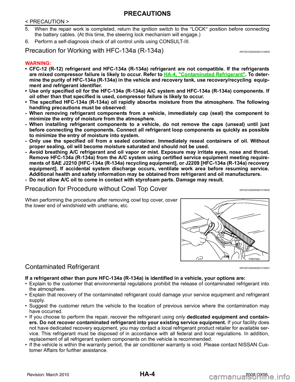
Precaution for Procedure without Cowl Top CoverINFOID:0000000001516630
When performing the procedure after removing cowl top cover, cover
the lower end of windshield with urethane, etc.
Contaminated RefrigerantINFOID:0000000001516631
If a refrigerant other than pure HFC-134a (R-134a) is identified in a vehicle, your options are:
• Explain to the customer that environmental regulations prohibit the release of contaminated refrigerant into
the atmosphere.
• Explain that recovery of the contaminated refri gerant could damage your service equipment and refrigerant
supply.
• Suggest the customer return the vehicle to the location of previous service where the contamination may have occurred.
• If you choose to perform the repair, recover the refrigerant using only dedicated equipment and contain- ers. Do not recover contamin ated refrigerant into your existing service equipment. If your facility does
not have dedicated recovery equipment, you may contact a local refrigerant product retailer for available ser-
vice. This refrigerant must be disposed of in acco rdance with all federal and local regulations. In addition,
replacement of all refrigerant system components on the vehicle is recommended.
• If the vehicle is within the warranty period, the air conditioner warranty is void. Please contact NISSAN Cus- tomer Affairs for further assistance.
PIIB3706J
Revision: March 2010 2008 QX56
Page 2219 of 4083
HA-14
< PREPARATION >
PREPARATION
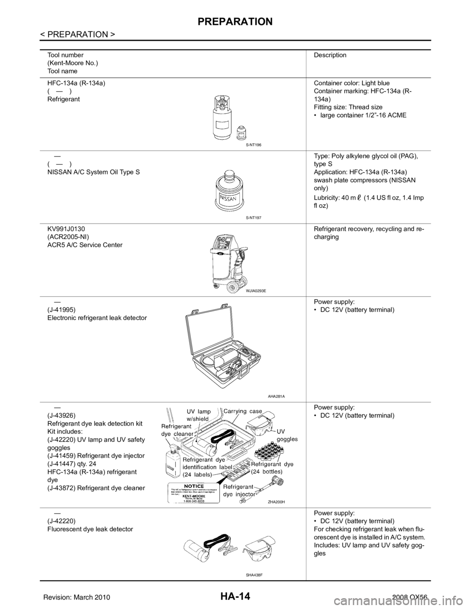
Tool number
(Kent-Moore No.)
Tool nameDescription
HFC-134a (R-134a)
(—)
Refrigerant Container color: Light blue
Container marking: HFC-134a (R-
134a)
Fitting size: Thread size
• large container 1/2”-16 ACME
—
(—)
NISSAN A/C System Oil Type S Type: Poly alkylene glycol oil (PAG),
type S
Application: HFC-134a (R-134a)
swash plate compressors (NISSAN
only)
Lubricity: 40 m (1.4 US fl oz, 1.4 Imp
fl oz)
KV991J0130
(ACR2005-NI)
ACR5 A/C Service Center Refrigerant recovery, recycling and re-
charging
—
(J-41995)
Electronic refrigerant leak detector Power supply:
• DC 12V (battery terminal)
—
(J-43926)
Refrigerant dye leak detection kit
Kit includes:
(J-42220) UV lamp and UV safety
goggles
(J-41459) Refrigerant dye injector
(J-41447) qty. 24
HFC-134a (R-134a) refrigerant
dye
(J-43872) Refrigerant dye cleaner Power supply:
• DC 12V (battery terminal)
—
(J-42220)
Fluorescent dye leak detector Power supply:
• DC 12V (battery terminal)
For checking refrigerant leak when flu-
orescent dye is installed in A/C system.
Includes: UV lamp and UV safety gog-
gles
S-NT196
S-NT197
WJIA0293E
AHA281A
ZHA200H
SHA438F
Revision: March 2010
2008 QX56
Page 2243 of 4083
HA-38
< ON-VEHICLE REPAIR >
LOW-PRESSURE PIPE
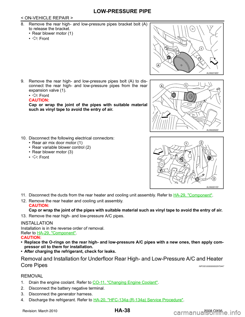
8. Remove the rear high- and low-pressure pipes bracket bolt (A)to release the bracket.
• Rear blower motor (1)
• : Front
9. Remove the rear high- and low-pressure pipes bolt (A) to dis- connect the rear high- and low-pressure pipes from the rear
expansion valve (1).
• : Front
CAUTION:
Cap or wrap the joint of the pipes with suitable material
such as vinyl tape to avoid the entry of air.
10. Disconnect the following electrical connectors: • Rear air mix door motor (1)
• Rear variable blower control (2)
• Rear blower motor (3)
• : Front
11. Disconnect the ducts from the rear heater and cooling unit assembly. Refer to HA-29, "
Component".
12. Remove the rear heater and cooling unit assembly. CAUTION:
Cap or wrap the joint of the pipes with suitable material such as viny l tape to avoid the entry of air.
13. Remove the rear high- and low-pressure A/C pipes.
INSTALLATION
Installation is in the reverse order of removal.
Refer to HA-29, "
Component".
CAUTION:
• Replace the O-rings on the rear high- and low-pr essure A/C pipes with a new ones, then apply com-
pressor oil to them for installation.
• After charging the refrigerant, check for leaks.
Removal and Installati on for Underfloor Rear High- and Low-Pressure A/C and Heater
Core Pipes
INFOID:0000000002975447
REMOVAL
1. Drain the engine coolant. Refer to CO-11, "Changing Engine Coolant".
2. Disconnect the battery negative terminal.
3. Disconnect the generator harness.
4. Discharge the refrigerant. Refer to HA-20, "
HFC-134a (R-134a) Service Procedure".
ALIIA0219ZZ
ALIIA0220ZZ
ALIIA0221ZZ
Revision: March 2010 2008 QX56
Page 2246 of 4083
HIGH-PRESSURE PIPEHA-41
< ON-VEHICLE REPAIR >
C
DE
F
G H
J
K L
M A
B
HA
N
O P
HIGH-PRESSURE PIPE
Removal and Installation for High-Pressure PipeINFOID:0000000001516657
REMOVAL
1. Remove the cowl top extension. Refer to EXT-18, "Removal and Installation".
2. Disconnect the battery negative terminal and positive battery terminal.
3. Reposition the IPDM E/R aside.
4. Remove the front right wheel and tire assembly. Refer to WT-48, "
Rotation".
5. Remove front right fender protector. Refer to EXT-23, "
Removal and Installation"
6. Position aside the front floor insulator.
7. Discharge the refrigerant. Refer to HA-20, "
HFC-134a (R-134a) Service Procedure".
8. Remove the low pressure pipe. Refer to HA-37, "
Removal and Installation for Low-Pressure Pipe".
9. Remove the high-pressure pipe. CAUTION:
Cap or wrap the joint of the pipe with suitable mate rial such as vinyl tape to avoid the entry of air.
INSTALLATION
Installation is in the reverse order of removal.
Refer to HA-29, "
Component".
CAUTION:
• Replace the O-ring of the high-pressure pipe with a new one, then apply compressor oil to it when
installing it.
• After charging refrigerant, check for leaks.
Removal and Installation for Rear High- and Low-Pressure A/C and Heater Core Pipes
INFOID:0000000002975448
REMOVAL
1. Discharge the refrigerant from the A/C system. Refer to HA-20, "HFC-134a (R-134a) Service Procedure".
2. Drain the coolant from the engine cooling system. Refer to CO-11, "
Changing Engine Coolant".
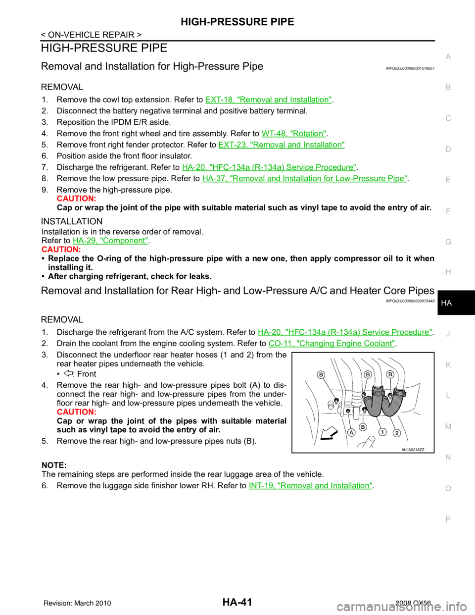
3. Disconnect the underfloor rear heater hoses (1 and 2) from the rear heater pipes underneath the vehicle.
• : Front
4. Remove the rear high- and low-pressure pipes bolt (A) to dis- connect the rear high- and low-pressure pipes from the under-
floor rear high- and low-pressure pipes underneath the vehicle.
CAUTION:
Cap or wrap the joint of the pipes with suitable material
such as vinyl tape to avo id the entry of air.
5. Remove the rear high- and low-pressure pipes nuts (B).
NOTE:
The remaining steps are performed inside the rear luggage area of the vehicle.
6. Remove the luggage side finisher lower RH. Refer to INT-19, "
Removal and Installation".
ALIIA0216ZZ
Revision: March 2010 2008 QX56
Page 2248 of 4083
HIGH-PRESSURE PIPEHA-43
< ON-VEHICLE REPAIR >
C
DE
F
G H
J
K L
M A
B
HA
N
O P
• Replace the O-rings on the rear high- and low-pr essure A/C pipes with a new ones, then apply com-
pressor oil to them for installation.
• After charging the refrigerant, check for leaks.
Removal and Installation for Underfloor Rear High- and Lo w-Pressure A/C and Heater
Core Pipes
INFOID:0000000002975449
REMOVAL
1. Drain the engine coolant. Refer to CO-11, "Changing Engine Coolant".
2. Disconnect the battery negative terminal.
3. Disconnect the generator harness.
4. Discharge the refrigerant. Refer to HA-20, "
HFC-134a (R-134a) Service Procedure".
5. Remove the front and rear bumper fascia. Refer to EXT-13, "
Removal and Installation" (front), EXT-15,
"Removal and Installation" (rear).
6. Reposition the front fender protector out of the way. Refer to EXT-23, "
Removal and Installation".
7. Disconnect the chassis harness connector.
8. Remove the spare wheel and tire.
9. Remove the tailpipe and tailpipe hanger bracket. Refer to EX-6, "
Removal and Installation".
10. Remove the seatbelt latch anchor. Refer to EX-6, "
Removal and Installation".
11. Remove the front floor heat shield.
12. Disconnect each end of the underfloor rear high- and low-pressure A/C and heater core pipes. Refer to HA-29, "
Component".
CAUTION:
Cap or wrap the joint of the pipes with suitable material such as viny l tape to avoid the entry of air.
13. Set two suitable jacks at the RH body mount points to support the vehicle body when it is separated from the RH side of the frame.
14. Remove the RH body mount bolts. Refer to BRM-2, "
Body Mounting".
15. Use the vehicle hoist to lower the RH side of the frame from the RH side of the body [approximately 305 mm (12 in)] until there is sufficient clearance to remove the underfloor rear high- and low-pressure A/C
and heater core pipes from between the body and the frame.
16. Remove the underfloor rear high- and low-pressure A/C and heater core pipes from the back of the vehi- cle.
INSTALLATION
Installation is in the reverse order of removal.
CAUTION:
• Replace the O-rings of the underfloor rear high - and low-pressure A/C and heater core pipes with
new ones, then apply compressor oil to them for installation.
• After charging refrigerant, check for leaks.
Revision: March 2010 2008 QX56
Page 2273 of 4083
![INFINITI QX56 2008 Factory Service Manual HAC-20
< FUNCTION DIAGNOSIS >[AUTOMATIC AIR CONDITIONER]
DIAGNOSIS SYSTEM (HVAC)
DIAGNOSIS SYSTEM (HVAC)
CONSULT-III Function (HVAC)INFOID:0000000001679777
CONSULT-III can display each diagnostic item INFINITI QX56 2008 Factory Service Manual HAC-20
< FUNCTION DIAGNOSIS >[AUTOMATIC AIR CONDITIONER]
DIAGNOSIS SYSTEM (HVAC)
DIAGNOSIS SYSTEM (HVAC)
CONSULT-III Function (HVAC)INFOID:0000000001679777
CONSULT-III can display each diagnostic item](/manual-img/42/57030/w960_57030-2272.png)
HAC-20
< FUNCTION DIAGNOSIS >[AUTOMATIC AIR CONDITIONER]
DIAGNOSIS SYSTEM (HVAC)
DIAGNOSIS SYSTEM (HVAC)
CONSULT-III Function (HVAC)INFOID:0000000001679777
CONSULT-III can display each diagnostic item using the diagnostic test modes shown following.
SELF-DIAGNOSIS
Display Item List
DATA MONITOR
Display Item List
Diagnostic mode
Description
SELF-DIAG RESULTS Displays A/C au to amp. self-diagnosis results.
DATA MONITOR Displays A/C auto amp. input/output data in real time.
CAN DIAG SUPPORT MNTR The result of transmit/receive diagnosis of CAN communication can be read. ECU PART NUMBER A/C auto amp. part number can be read.
DTC Description
Reference page
B2573 Battery voltage out of range CHG-10, "
Inspection Procedure"
B2578 In-vehicle sensor circuit out of range (low)
HAC-81, "In-Vehicle Sensor Diagnosis Procedure"B2579 In-vehicle sensor circuit out of range (high)
B257B Ambient sensor circuit short HAC-78, "
Ambient Sensor Diagnosis Procedure"B257C Ambient sensor circuit open
B257F Optical sensor (Driver) circuit open or short HAC-84, "
Optical Sensor Diagnosis Procedure".
B2580 Optical sensor (Passenger) circuit open or short
B2581 Intake sensor circuit short HAC-86, "
Intake Sensor Diagnosis Procedure"B2582 Intake sensor circuit open
U1000 CAN bus fault LAN-14, "
Trouble Diagnosis Flow Chart"
Monitor itemValue Contents
BATT VIA CAN "V" Displays battery voltage signal.
IGN VIA CAN "ON/OFF" Displays ignition switch signal.
DVR SUNLD SEN "w/m2" Displays optical sensor (driver) signal.
PAS SUNLD SEN "w/m2" Displays optical sensor (passenger) signal.
AMB TEMP SEN "° C" Displays ambient sensor signal.
EVAP TEMP SEN "° C" Displays intake sensor signal.
INCAR TMP SEN "° C" Displays in-vehicle sensor signal.
RR TEMPSET FR "V" Displays air mix door (front) set point signal.
RR TEMPSET RR "V" Displays air mix door (rear) set point signal.
MODE FDBCK "V" Displays mode door motor feedback signal.
DVR MIX FDBCK "V" Displays air mix door motor (driver) feedback signal.
PAS MIX FDBCK "V" Displays air mix door motor (passenger) feedback signal.
RR FDBCK "V" Displays air mix door motor (rear) feedback signal.
DEF FDBCK "V" Displays defroster door motor feedback signal.
Revision: March 2010 2008 QX56
Page 2275 of 4083
![INFINITI QX56 2008 Factory Service Manual HAC-22
< FUNCTION DIAGNOSIS >[AUTOMATIC AIR CONDITIONER]
SELF-DIAGNOSIS FUNCTION
SELF-DIAGNOSIS FUNCTION
A/C Auto Amp. Self-DiagnosisINFOID:0000000001679779
A/C SYSTEM SELF-DIAGNOSIS FUNCTION
The self INFINITI QX56 2008 Factory Service Manual HAC-22
< FUNCTION DIAGNOSIS >[AUTOMATIC AIR CONDITIONER]
SELF-DIAGNOSIS FUNCTION
SELF-DIAGNOSIS FUNCTION
A/C Auto Amp. Self-DiagnosisINFOID:0000000001679779
A/C SYSTEM SELF-DIAGNOSIS FUNCTION
The self](/manual-img/42/57030/w960_57030-2274.png)
HAC-22
< FUNCTION DIAGNOSIS >[AUTOMATIC AIR CONDITIONER]
SELF-DIAGNOSIS FUNCTION
SELF-DIAGNOSIS FUNCTION
A/C Auto Amp. Self-DiagnosisINFOID:0000000001679779
A/C SYSTEM SELF-DIAGNOSIS FUNCTION
The self-diagnosis function is built into the A/C aut
o amp. to quickly locate the cause of malfunctions.
DESCRIPTION
The self-diagnostic system diagnoses sensors, CAN sys tem, and battery voltage on A/C auto amp. Refer to
applicable sections (items) for details. Fault codes (if any are present) will be displayed in the ambient temper-
ature display area. Refer to HAC-23, "
A/C System Self-Diagnosis Code Chart".
SELF-DIAGNOSTIC MODE
NOTE:
Radio must be off.
1. On the A/C and AV switch asse mbly, press the "SETTING" but-
ton and twist the volume knob clockwise and counterclockwise
until the Self-Diagnosis screen shows on the display.
2. Scroll down to "Confirmation/Adjustment" and press the "ENTER" button.
3. Scroll down to "Climate Control" and press the "ENTER" button.
4. The fan bars will flash on the display during the self-test, and then the fault codes will display in the ambient temperature area.
They will continue scrolling until diagnostic mode is exited.
5. Exit by pressing the "BACK" button on A/C and AV switch assembly until display returns to its normal operation screen.
HVAC system will be OFF.
The self-diagnostic system diagnoses sensors, CAN sys tem, and battery voltage on A/C auto amp. Refer to
applicable sections (items) for details. Fault codes (if any are present) will be displayed in the ambient temper-
ature display area. Refer to HAC-23, "
A/C System Self-Diagnosis Code Chart".
A/C and AV Switch Asse mbly Self-DiagnosisINFOID:0000000001679780
A/C and AV switch assembly self-diagnosis function
The ON/OFF operation (continuity) of each switch in the A/C and AV switch assembly can be checked.
Self-diagnosis mode
AWNIA0098ZZ
AWIIA0081ZZ
Revision: March 2010 2008 QX56