Page 3518 of 4083
HYDRAULIC LINEST-27
< REMOVAL AND INSTALLATION >
C
DE
F
H I
J
K L
M A
B
ST
N
O P
HYDRAULIC LINE
Removal and InstallationINFOID:0000000004920103
Refer to the following illustration for hydralic line removal.
Installation is in the reverse order of removal.
1. Reservoir tank 2. Suction hose 3. High pressure hose
4. Oil cooler 5. Steering gear assembly 6. Reservoir tank bracket
7. Eye bolt
WGIA0096E
Revision: March 2010 2008 QX56
Page 3519 of 4083
ST-28
< REMOVAL AND INSTALLATION >
HYDRAULIC LINE
• Confirm mating marks are aligned with hose and clamp, then cor-rect if needed.
• To install eye joint, align projection of eye joint with notch of power steering pump, and attach eye joint to power steering pump prop-
erly. Tighten eye bolt by hand fully, then torque to specification.
SGIA0563E
WGIA0089E
Revision: March 2010 2008 QX56
Page 3520 of 4083
STEERING COLUMNST-29
< DISASSEMBLY AND ASSEMBLY >
C
DE
F
H I
J
K L
M A
B
ST
N
O P
DISASSEMBLY AND ASSEMBLY
STEERING COLUMN
Disassembly and AssemblyINFOID:0000000004920104
DISASSEMBLY
1. Remove bolt from upper joint, then remove upper joint from steering column assembly.
2. Remove ignition switch tamper resistant self-shear screws with a drill or other suitable tool.
ASSEMBLY
• Assembly is in the reverse order of disassembly.
• Install new tamper resistant self-shear screws.
CAUTION:
Any time the ignition switch has been disconnected, removed
or installed, the keys must be re -registered in the BCM. Refer to
CONSULT-III operation manual IVIS/NVIS.
INSPECTION AFTER ASSEMBLY
When the steering wheel does not turn smoothl y, check the steering column as follows:
1. Steering column assembly 2. Upper joint 3. Ignition switch
4. Tamper resistant self-shear screw
WGIA0091E
WGIA0009E
Revision: March 2010 2008 QX56
Page 3521 of 4083

ST-30
< DISASSEMBLY AND ASSEMBLY >
STEERING COLUMN
1. Check the column bearings for damage or unevenness. Lubricate with recommended multi-purposegrease. Replace the steering column as an assembly, if necessary.
2. Check the column tube for deformation or breakage. R eplace the steering column as an assembly, if nec-
essary.
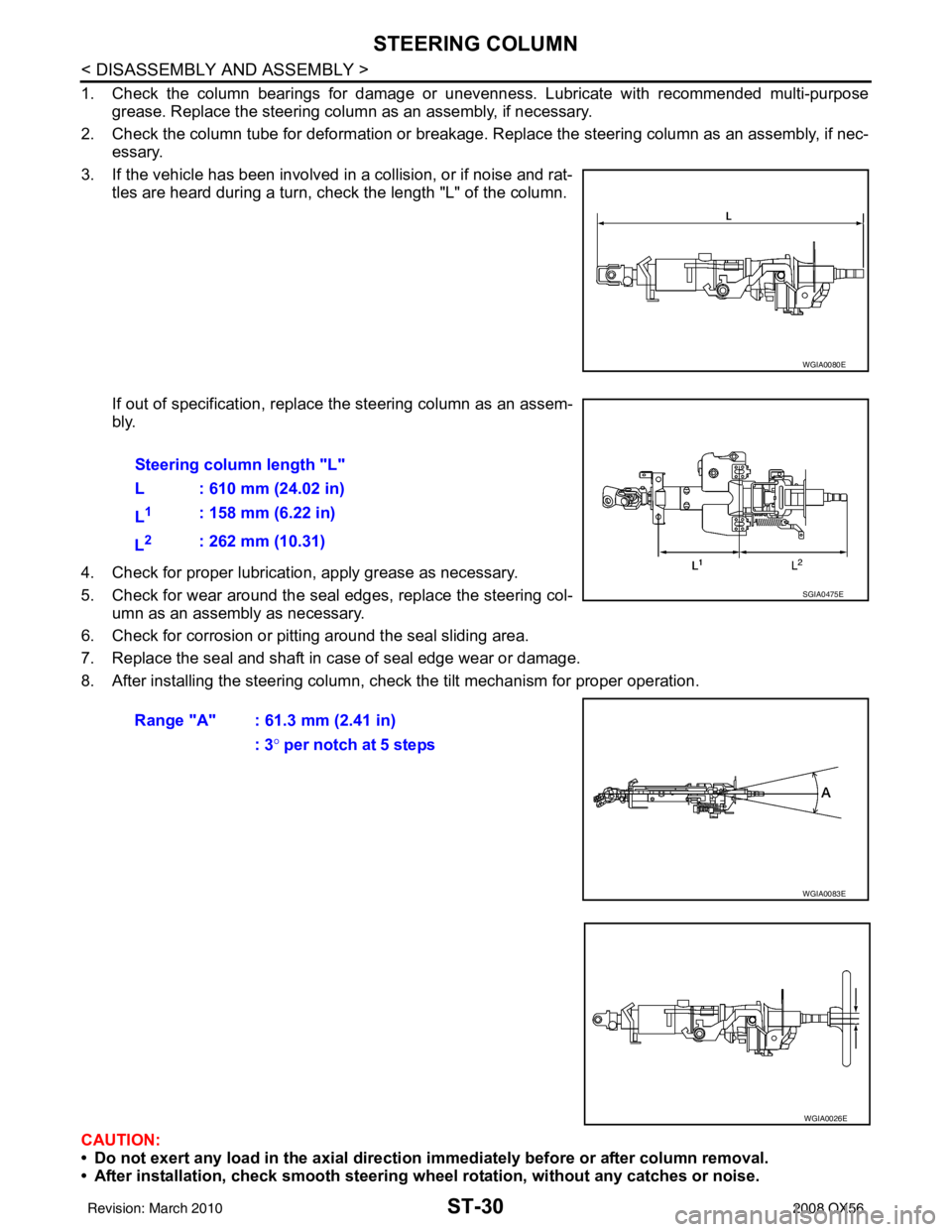
3. If the vehicle has been involved in a collision, or if noise and rat- tles are heard during a turn, check the length "L" of the column.
If out of specification, replace the steering column as an assem-
bly.
4. Check for proper lubrication, apply grease as necessary.
5. Check for wear around the seal edges, replace the steering col- umn as an assembly as necessary.
6. Check for corrosion or pitting around the seal sliding area.
7. Replace the seal and shaft in case of seal edge wear or damage.
8. After installing the steering column, check the tilt mechanism for proper operation.
CAUTION:
• Do not exert any load in the axial direction immediately before or after column removal.
• After installation, check smooth steering wh eel rotation, without any catches or noise.
WGIA0080E
Steering column length "L"
L : 610 mm (24.02 in)
L
1: 158 mm (6.22 in)
L
2: 262 mm (10.31)
Range "A" : 61.3 mm (2.41 in) : 3° per notch at 5 steps
SGIA0475E
WGIA0083E
WGIA0026E
Revision: March 2010 2008 QX56
Page 3522 of 4083

POWER STEERING GEAR AND LINKAGEST-31
< DISASSEMBLY AND ASSEMBLY >
C
DE
F
H I
J
K L
M A
B
ST
N
O P
POWER STEERING GEAR AND LINKAGE
Disassembly and AssemblyINFOID:0000000004920105
CAUTION:
• Secure steering gear assembly with a vise, using copper plates or something similar to prevent it
from being damaged. Do not grip cylinder with a vise.
• Before performing disassembly, clean steering gear assembly with kerosene. Be careful not to bring
any kerosene into contact with the di scharge and return port connectors.
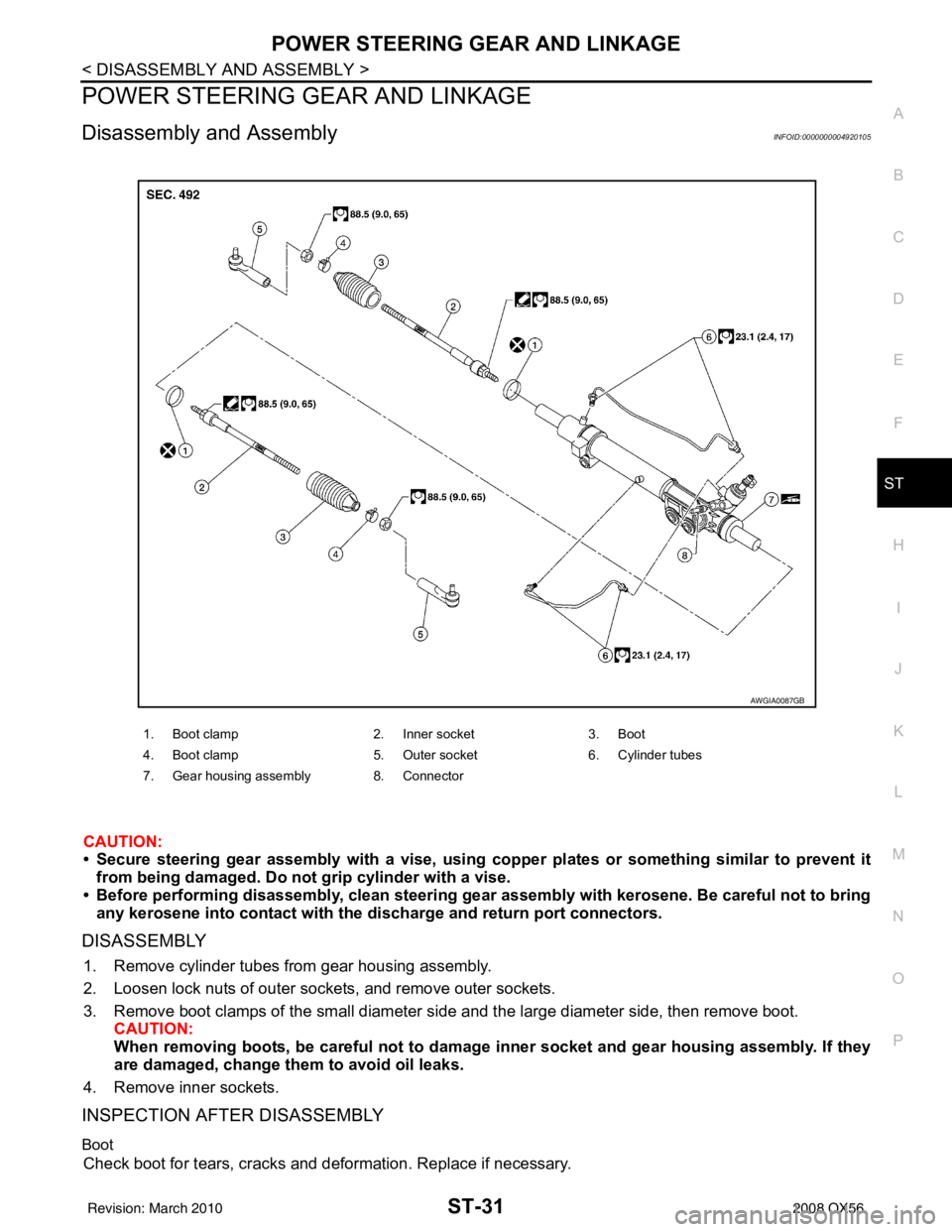
DISASSEMBLY
1. Remove cylinder tubes from gear housing assembly.
2. Loosen lock nuts of outer sockets, and remove outer sockets.
3. Remove boot clamps of the small diameter si de and the large diameter side, then remove boot.
CAUTION:
When removing boots, be careful not to damage inner socket and gear housing assembly. If they
are damaged, change th em to avoid oil leaks.
4. Remove inner sockets.
INSPECTION AFTER DISASSEMBLY
Boot
Check boot for tears, cracks and deformation. Replace if necessary.
1. Boot clamp 2. Inner socket3. Boot
4. Boot clamp 5. Outer socket6. Cylinder tubes
7. Gear housing assembly 8. Connector
AWGIA0087GB
Revision: March 2010 2008 QX56
Page 3523 of 4083

ST-32
< DISASSEMBLY AND ASSEMBLY >
POWER STEERING GEAR AND LINKAGE
Gear Housing Assembly
Check gear housing assembly for dents, cracks or damage. Replace as an assembly if necessary.
Outer Socket and Inner Socket
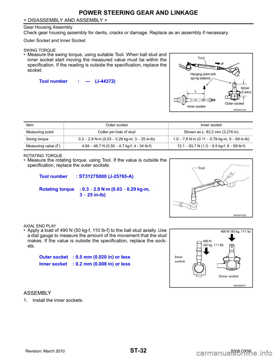
SWING TORQUE• Measure the swing torque, using suitable Tool. When ball stud and
inner socket start moving the measured value must be within the
specification. If the reading is out side the specification, replace the
socket.
ROTATING TORQUE• Measure the rotating torque, using Tool. If the value is outside the
specification, replace the outer sockets.
AXIAL END PLAY• Apply a load of 490 N (50 kg-f, 110 lb-f) to the ball stud axially. Usea dial gauge to measure the amount of the movement that the stud
makes. If the value is outside the specification, replace the sock-
ets.
ASSEMBLY
1. Install the inner sockets. Tool number : — (J-44372)
WGIA0131E
Item
Outer socket Inner socket
Measuring point Cotter pin hole of stud Shown as L: 83.2 mm (3.276 in)
Swing torque 0.3 − 2.9 N·m (0.03 − 0.29 kg-m, 3 − 25 in-lb) 1.0 − 7.8 N·m (0.11 − 0.79 kg-m, 9 − 69 in-lb)
Measuring value (F) 4.84 − 46.7 N (0.50 − 4.7 kg-f, 4 - 34 lb-f) 12.1 − 93.7 N (1.3 − 9.5 kg-f, 9 − 69 lb-f)
Tool number : ST3127S000 (J-25765-A)
Rotating torque : 0.3 − 2.9 N·m (0.03 − 0.29 kg-m,
3 − 25 in-lb)
WGIA0132E
Outer socket : 0.5 mm (0.020 in) or less
Inner socket : 0.2 mm (0.008 in) or less
SGIA0057E
Revision: March 2010 2008 QX56
Page 3524 of 4083
POWER STEERING GEAR AND LINKAGEST-33
< DISASSEMBLY AND ASSEMBLY >
C
DE
F
H I
J
K L
M A
B
ST
N
O P
2. Install the large-diameter side of the boots to the gear housing assembly.
3. Install the small-diameter side of the boots to the groove of the inner sockets.
4. Install the boot clamps to the boots, as shown. CAUTION:
Do not reuse the large-diameter boot clamps.
5. Crimp the large-diameter boot clamps, using Tool.
6. Install the cylinder tubes to the gear housing assembly.
7. Install the lock nuts and outer sockets to the inner sockets.
SGIA0550E
AST139
Tool number : KV40107300 ( — )
RAC1133D
Revision: March 2010 2008 QX56
Page 3525 of 4083
ST-34
< DISASSEMBLY AND ASSEMBLY >
POWER STEERING GEAR AND LINKAGE
8. Thread the outer sockets onto the inner sockets to the specifiedlength "L", then tighten the lock nuts to the specification. Refer to
ST-23, "
Removal and Installation". Reconfirm that the tie-rod
length "L" is within specification.
Maximum inner socket
length "L" : 115.2 mm (4.54 in)
SGIA0167E
Revision: March 2010
2008 QX56