2008 INFINITI QX56 coolant level
[x] Cancel search: coolant levelPage 2610 of 4083
MA-12
< ON-VEHICLE MAINTENANCE >
RECOMMENDED FLUIDS AND LUBRICANTS
RECOMMENDED FLUIDS AND LUBRICANTS
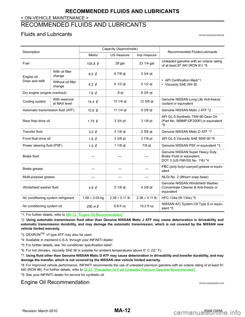
Fluids and LubricantsINFOID:0000000001606168
*1: For further details, refer to MA-12, "Engine Oil Recommendation" .
*2: Using automatic transmission fluid other than Genuine NISSAN Matic J ATF may cause deterioration in driveability and
automatic transmission durability, and may damage the automatic transmission, which is not covered by the NISSAN new
vehicle limited warranty.
*3: DEXRON
TM VI type ATF may also be used.
*4: Available in mainland U.S.A. through your INFINITI dealer.
*5: For further details, see “Air conditioner specification label”.
*6: For hot climates, viscosity SAE 90 is suitable for ambient te mperatures above 0° C (32 ° F).
*7: Using fluid other than Genuine NISSAN Matic D ATF may cause de terioration in driveability and transfer durability, and may
damage the transfer, which is not covered by the NISSAN new vehicle limited warranty.
*8: For improved vehicle performance, INFINITI recommends the use of unleaded premium gasoline with an octane rating of at leas t 91
AKI (RON 96). For further details, refer to GI-27, "
Precaution for Fuel (Unleaded Premium Gasoline Recommended)".
*9: See your INFINITI dealer for service for synthetic oil.
Engine Oil RecommendationINFOID:0000000006211816
Description Capacity (Approximate)
Recommended Fluids/Lubricants
Metric US measure Imp measure
Fuel 105.8 28 gal 23 1/4 gal Unleaded gasoline with an octane rating
of at least 87 AKI (RON 91) *8
Engine oil
Drain and refill With oil filter
change
6.5
6 7/8 qt 5 3/4 qt
• API Certification Mark*1
• Viscosity SAE 5W-30
Without oil filter
change
6.2
6 1/2 qt 5 1/2 qt
Dry engine (engine overhaul) 7.6 8 qt
6 3/4 qt
Cooling system With reservoir
at MAX level
14.4
15 1/4 qt 12 5/8 qt Genuine NISSAN Long Life Anti-freeze
coolant or equivalent
Automatic transmission fluid (ATF) 10.6 11 1/4 qt 9 3/8 qt Genuine NISSAN Matic J ATF *2
Rear final drive oil 1.75 3 3/4 pt 3 1/8 pt API GL-5 Synthetic 75W-90 Gear Oil
(Part No. 999MP-DF200P) or equivalent
*9
Transfer fluid 3.0 3 1/8 qt 2 5/8 qt Genuine NISSAN Matic D ATF *7
Front final drive oil 1.6 3 3/8 pt 2 7/8 pt API GL-5 Viscosity SAE 80W-90 *6
Power steering fluid (PSF) 1.0 1 1/8 qt 7/8 qt Genuine NISSAN PSF or equivalent *3
Brake fluid —— —Genuine NISSAN Super Heavy Duty
Brake Fluid or equivalent,
DOT 3 (US FMVSS No. 116) *4
Brake grease —— —PBC (poly butyl cuprysil) grease or equiv-
alent
Multi-purpose grease —— — NLGI No. 2 (lithium soap base)
Windshield washer fluid 4.9 5 1/8 qt 4 3/8 qt Genuine NISSAN Windshield Washer
Concentrate Cleaner & Anti-freeze or
equivalent
Air conditioning system refrigerant 1.08 ± 0.05 kg 2.38 ± 0.11 lb 2.38 ± 0.11 lb HFC-134a (R-134a) *5
Air conditioning system oil 290 m9.8 fl oz 10.2 fl oz NISSAN A/C System Oil Type S or equiv-
alent *5
Revision: March 2010
2008 QX56
Page 2614 of 4083
MA-16
< ON-VEHICLE MAINTENANCE >
ENGINE MAINTENANCE
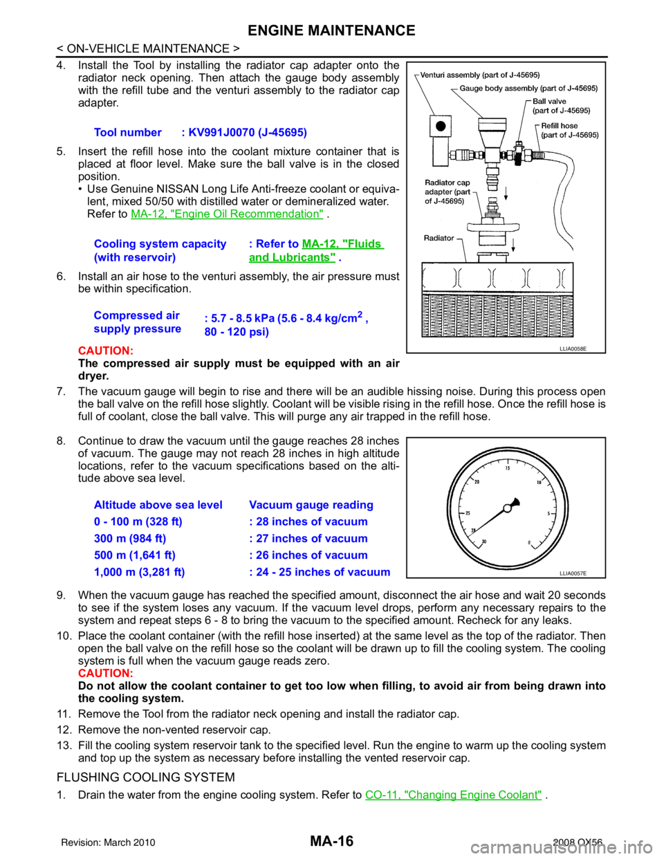
4. Install the Tool by installing the radiator cap adapter onto theradiator neck opening. Then attach the gauge body assembly
with the refill tube and the venturi assembly to the radiator cap
adapter.
5. Insert the refill hose into the coolant mixture container that is placed at floor level. Make sure the ball valve is in the closed
position.
• Use Genuine NISSAN Long Life Anti-freeze coolant or equiva-
lent, mixed 50/50 with distilled water or demineralized water.
Refer to MA-12, "
Engine Oil Recommendation" .
6. Install an air hose to the venturi assembly, the air pressure must be within specification.
CAUTION:
The compressed air supply must be equipped with an air
dryer.
7. The vacuum gauge will begin to rise and there will be an audible hissing noise. During this process open the ball valve on the refill hose slightly. Coolant will be vi sible rising in the refill hose. Once the refill hose is
full of coolant, close the ball valve. This will purge any air trapped in the refill hose.
8. Continue to draw the vacuum until the gauge reaches 28 inches of vacuum. The gauge may not reach 28 inches in high altitude
locations, refer to the vacuum specifications based on the alti-
tude above sea level.
9. When the vacuum gauge has reached the specifi ed amount, disconnect the air hose and wait 20 seconds
to see if the system loses any vacuum. If the vacuum level drops, perform any necessary repairs to the
system and repeat steps 6 - 8 to bring the vacuum to the specified amount. Recheck for any leaks.
10. Place the coolant container (with the refill hose insert ed) at the same level as the top of the radiator. Then
open the ball valve on the refill hose so the coolant will be drawn up to fill the cooling system. The cooling
system is full when the vacuum gauge reads zero.
CAUTION:
Do not allow the coolant container to get too low when filling, to avoid air from being drawn into
the cooling system.
11. Remove the Tool from the radiator neck opening and install the radiator cap.
12. Remove the non-vented reservoir cap.
13. Fill the cooling system reservoir tank to the specif ied level. Run the engine to warm up the cooling system
and top up the system as necessary before installing the vented reservoir cap.
FLUSHING COOLING SYSTEM
1. Drain the water from the engine cooling system. Refer to CO-11, "Changing Engine Coolant" .
Tool number : KV991J0070 (J-45695)
Cooling system capacity
(with reservoir)
: Refer to
MA-12, "
Fluids
and Lubricants" .
Compressed air
supply pressure : 5.7 - 8.5 kPa (5.6 - 8.4 kg/cm
2 ,
80 - 120 psi)
LLIA0058E
Altitude above sea level Vacuum gauge reading
0 - 100 m (328 ft) : 28 inches of vacuum
300 m (984 ft) : 27 inches of vacuum
500 m (1,641 ft) : 26 inches of vacuum
1,000 m (3,281 ft) : 24 - 25 inches of vacuum
LLIA0057E
Revision: March 2010 2008 QX56
Page 2615 of 4083
ENGINE MAINTENANCEMA-17
< ON-VEHICLE MAINTENANCE >
C
DE
F
G H
I
J
K L
M B
MA
N
O A
2. Fill the radiator and the reservoir tank (to the “MAX”
line), with water. Reinstall the radiator cap and leave
the vented reservoir cap off.
3. Run the engine until it reaches normal operating temperature.
4. Press the engine accelerator two or three times under no-load.
5. Stop the engine and wait until it cools down.
6. Drain the water from the engine cooling system. Refer to CO-11, "
Changing Engine Coolant" .
7. Repeat steps 2 through 6 until clear water begins to drain from the radiator.
Checking Fuel LineINFOID:0000000001606172
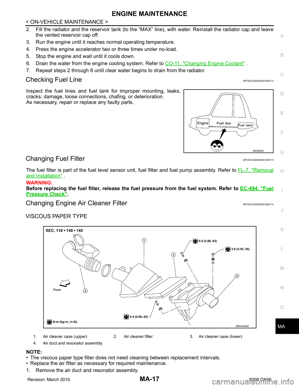
Inspect the fuel lines and fuel tank for improper mounting, leaks,
cracks, damage, loose connections, chafing, or deterioration.
As necessary, repair or replace any faulty parts.
Changing Fuel FilterINFOID:0000000001606173
The fuel filter is part of the fuel level sensor unit, fuel filter and fuel pump assembly. Refer to FL-7, "Removal
and Installation" .
WARNING:
Before replacing the fuel filter, release the fuel pressure from the fuel system. Refer to EC-494, "
Fuel
Pressure Check".
Changing Engine Air Cleaner FilterINFOID:0000000001606174
VISCOUS PAPER TYPE
NOTE:
• The viscous paper type filter does not need cleaning between replacement intervals.
• Replace the air filter as necessary for required maintenance.
1. Remove the air duct and resonator assembly.
SMA803A
1. Air cleaner case (upper) 2. Air cleaner filter3. Air cleaner case (lower)
4. Air duct and resonator assembly
WBIA0465E
Revision: March 2010 2008 QX56
Page 2652 of 4083
MWI
METER SYSTEMMWI-7
< FUNCTION DIAGNOSIS >
C
DE
F
G H
I
J
K L
M B A
O P
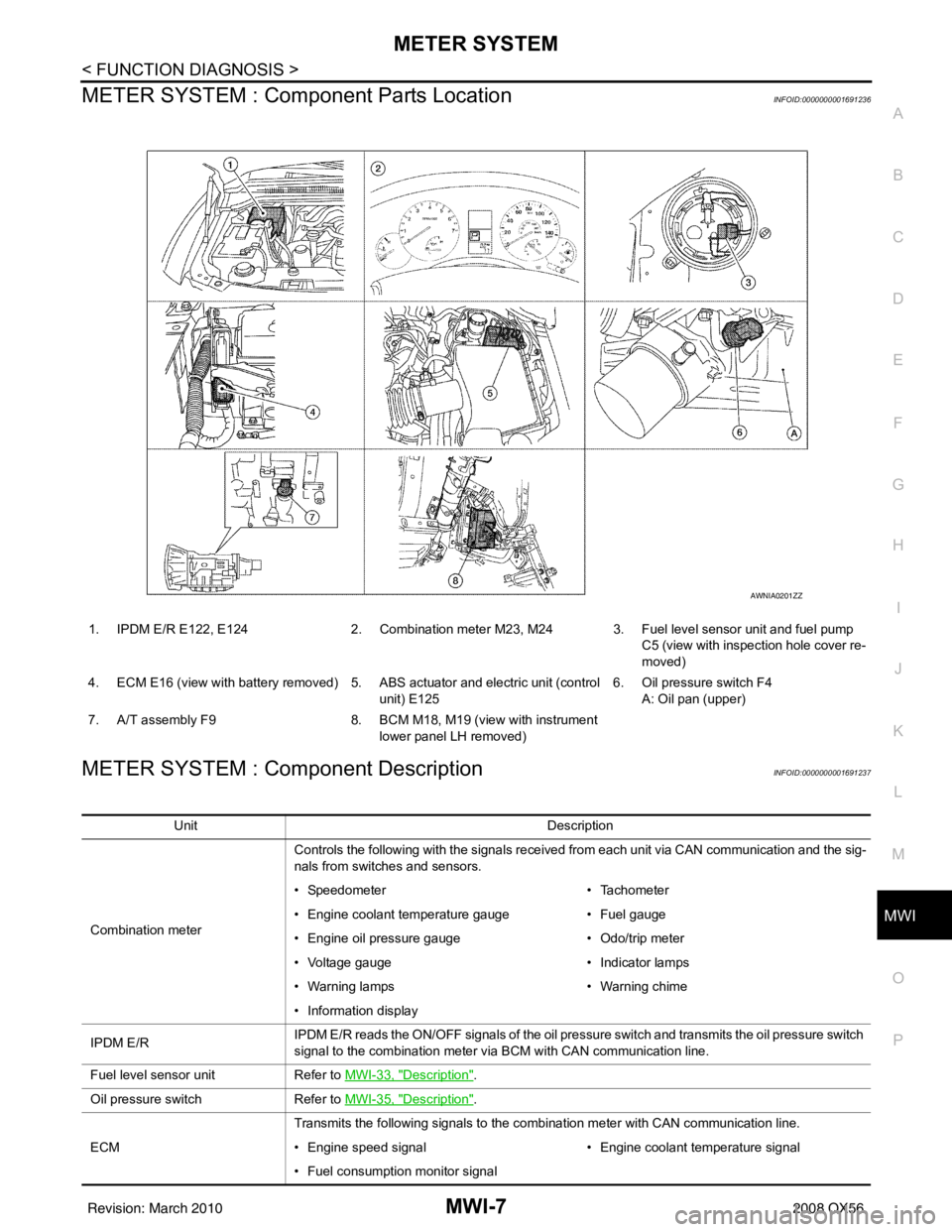
METER SYSTEM : Com ponent Parts LocationINFOID:0000000001691236
METER SYSTEM : Component DescriptionINFOID:0000000001691237
1. IPDM E/R E122, E124 2. Combination meter M23, M24 3. Fuel level sensor unit and fuel pump
C5 (view with inspection hole cover re-
moved)
4. ECM E16 (view with battery removed) 5. ABS actuator and electric unit (control unit) E1256. Oil pressure switch F4
A: Oil pan (upper)
7. A/T assembly F9 8. BCM M18, M19 (view with instrument
lower panel LH removed)
AWNIA0201ZZ
Unit Description
Combination meter Controls the following with the signals received from each unit via CAN communication and the sig-
nals from switches and sensors.
• Speedometer
• Tachometer
• Engine coolant temperature gauge • Fuel gauge
• Engine oil pressure gauge • Odo/trip meter
• Voltage gauge • Indicator lamps
• Warning lamps • Warning chime
• Information display
IPDM E/R IPDM E/R reads the ON/OFF signals of the oil pressure switch and transmits the oil pressure switch
signal to the combination meter via BCM with CAN communication line.
Fuel level sensor unit Refer to MWI-33, "
Description".
Oil pressure switch Refer to MWI-35, "
Description".
ECM Transmits the following signals to the combination meter with CAN communication line.
• Engine speed signal
• Engine coolant temperature signal
• Fuel consumption monitor signal
Revision: March 2010 2008 QX56
Page 2655 of 4083
MWI-10
< FUNCTION DIAGNOSIS >
METER SYSTEM
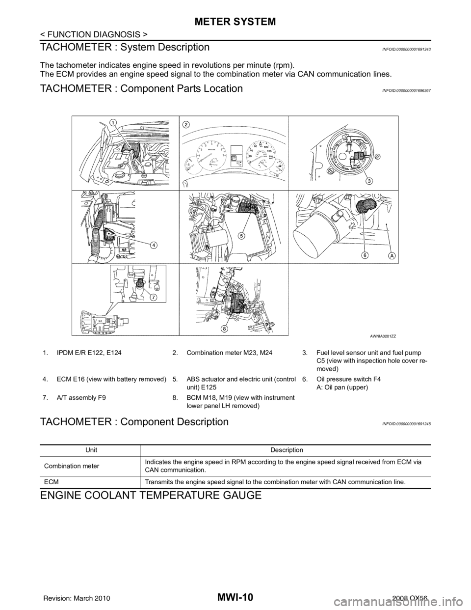
TACHOMETER : System Description
INFOID:0000000001691243
The tachometer indicates engine speed in revolutions per minute (rpm).
The ECM provides an engine speed signal to the co mbination meter via CAN communication lines.
TACHOMETER : Component Parts LocationINFOID:0000000001696367
TACHOMETER : Component DescriptionINFOID:0000000001691245
ENGINE COOLANT TEMPERATURE GAUGE
1. IPDM E/R E122, E1242. Combination meter M23, M24 3. Fuel level sensor unit and fuel pump
C5 (view with inspection hole cover re-
moved)
4. ECM E16 (view with battery removed) 5. ABS actuator and electric unit (control
unit) E125 6. Oil pressure switch F4
A: Oil pan (upper)
7. A/T assembly F9 8. BCM M18, M19 (view with instrument
lower panel LH removed)
AWNIA0201ZZ
Unit Description
Combination meter Indicates the engine speed in RPM according to the engine speed signal received from ECM via
CAN communication.
ECM Transmits the engine speed signal to the combination meter with CAN communication line.
Revision: March 2010 2008 QX56
Page 2656 of 4083
MWI
METER SYSTEMMWI-11
< FUNCTION DIAGNOSIS >
C
DE
F
G H
I
J
K L
M B A
O P
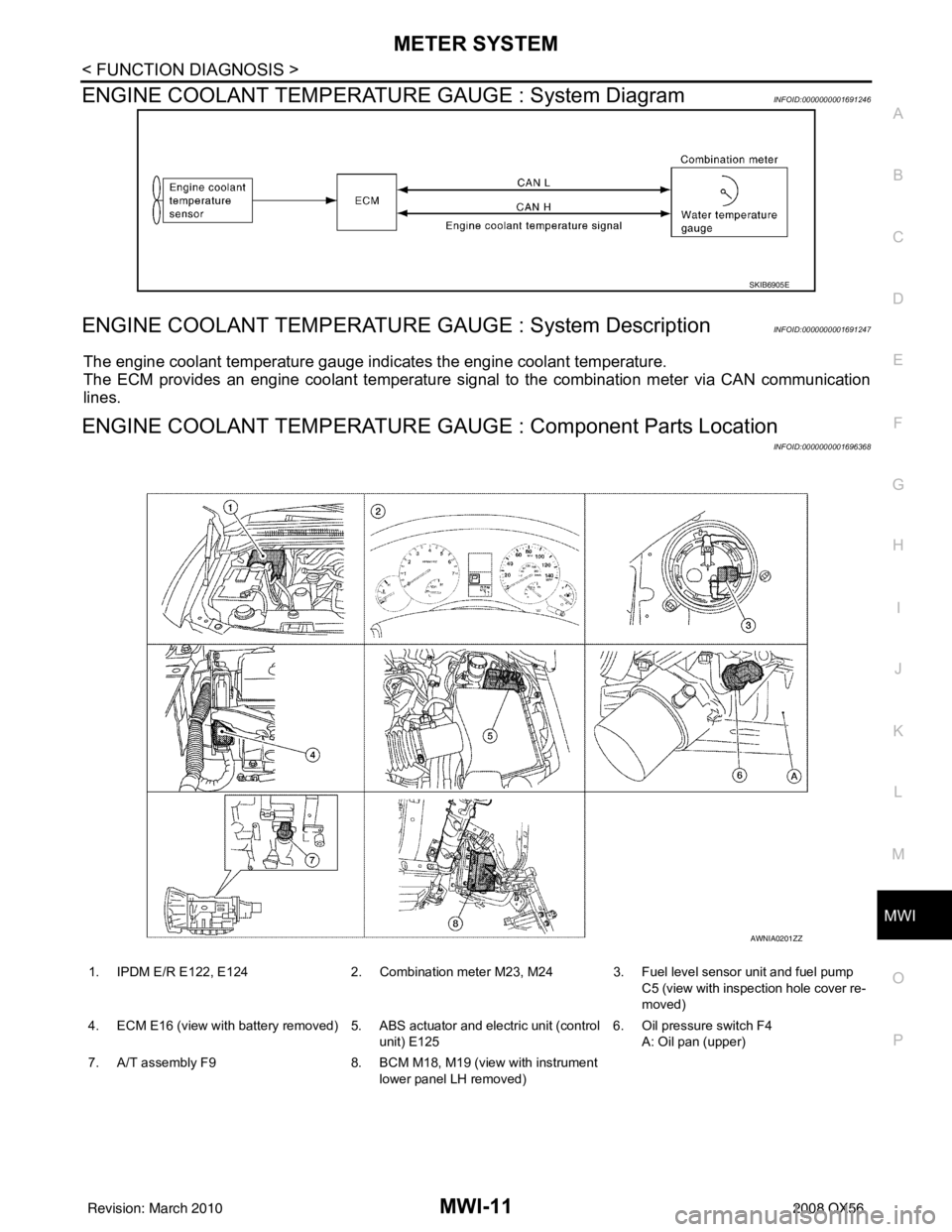
ENGINE COOLANT TEMPERATURE GAUGE : System DiagramINFOID:0000000001691246
ENGINE COOLANT TEMPERATURE GAUGE : System DescriptionINFOID:0000000001691247
The engine coolant temperature gauge indicates the engine coolant temperature.
The ECM provides an engine coolant temperature signal to the combination meter via CAN communication
lines.
ENGINE COOLANT TEMPERATURE GA UGE : Component Parts Location
INFOID:0000000001696368
SKIB6905E
1. IPDM E/R E122, E124 2. Combination meter M23, M24 3. Fuel level sensor unit and fuel pump
C5 (view with inspection hole cover re-
moved)
4. ECM E16 (view with battery removed) 5. ABS actuator and electric unit (control unit) E1256. Oil pressure switch F4
A: Oil pan (upper)
7. A/T assembly F9 8. BCM M18, M19 (view with instrument
lower panel LH removed)
AWNIA0201ZZ
Revision: March 2010 2008 QX56
Page 2657 of 4083
MWI-12
< FUNCTION DIAGNOSIS >
METER SYSTEM
ENGINE COOLANT TEMPERATURE GAUGE : Component Description
INFOID:0000000001691249
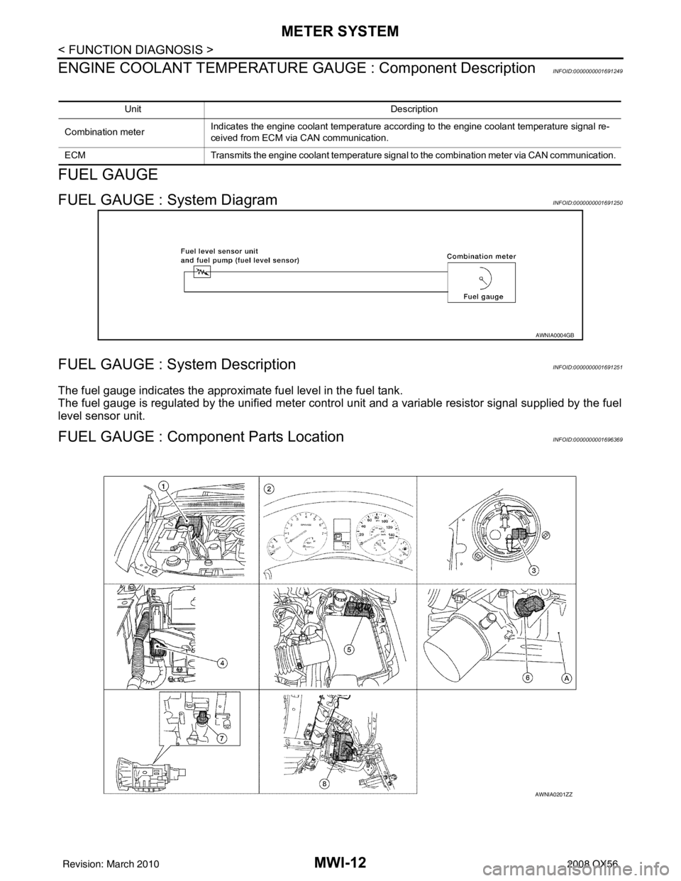
FUEL GAUGE
FUEL GAUGE : System DiagramINFOID:0000000001691250
FUEL GAUGE : System DescriptionINFOID:0000000001691251
The fuel gauge indicates the approximate fuel level in the fuel tank.
The fuel gauge is regulated by the unified meter control unit and a variable resistor signal supplied by the fuel
level sensor unit.
FUEL GAUGE : Compone nt Parts LocationINFOID:0000000001696369
Unit Description
Combination meter Indicates the engine coolant temperature according to the engine coolant temperature signal re-
ceived from ECM via CAN communication.
ECM Transmits the engine coolant temperature signal to the combination meter via CAN communication.
AWNIA0004GB
AWNIA0201ZZ
Revision: March 2010 2008 QX56
Page 3042 of 4083

PRECAUTIONSRSU-3
< PRECAUTION >
C
DF
G H
I
J
K L
M A
B
RSU
N
O P
5. When the repair work is completed, return the ignition switch to the ″LOCK ″ position before connecting
the battery cables. (At this time, the steering lock mechanism will engage.)
6. Perform a self-diagnosis check of al l control units using CONSULT-III.
Precaution for Rear SuspensionINFOID:0000000001534647
• When installing the rubber bushings, the final tightening must be done under unladen condition and with the
tires on level ground. Oil will shorten the life of the rubber bushings, so wipe off any spilled oil immediately.
• Unladen condition means the fuel tank, engine coolant and lubricants are at the full specification. The spare
tire, jack, hand tools, and mats are in their designated positions.
• After installing suspension components, check the wheel alignment.
• Caulking nuts are not reusable. Always use new caulking nuts for installation. New caulking nuts are pre- oiled, do not apply any additional lubrication.
Revision: March 2010 2008 QX56