2008 INFINITI QX56 E125
[x] Cancel search: E125Page 548 of 4083
![INFINITI QX56 2008 Factory Service Manual VDC OFF SWITCHBRC-81
< COMPONENT DIAGNOSIS > [VDC/TCS/ABS]
C
D
E
G H
I
J
K L
M A
B
BRC
N
O P
VDC OFF SWITCH
DescriptionINFOID:0000000001686354
VDC OFF switch can deactivate (t urn OFF) the VDC/TCS fun INFINITI QX56 2008 Factory Service Manual VDC OFF SWITCHBRC-81
< COMPONENT DIAGNOSIS > [VDC/TCS/ABS]
C
D
E
G H
I
J
K L
M A
B
BRC
N
O P
VDC OFF SWITCH
DescriptionINFOID:0000000001686354
VDC OFF switch can deactivate (t urn OFF) the VDC/TCS fun](/manual-img/42/57030/w960_57030-547.png)
VDC OFF SWITCHBRC-81
< COMPONENT DIAGNOSIS > [VDC/TCS/ABS]
C
D
E
G H
I
J
K L
M A
B
BRC
N
O P
VDC OFF SWITCH
DescriptionINFOID:0000000001686354
VDC OFF switch can deactivate (t urn OFF) the VDC/TCS function by pressing the VDC OFF switch.
Component Function CheckINFOID:0000000001686355
1.CHECK VDC OFF SWITCH OPERATION
Turn ON/OFF the VDC OFF switch and check that the VDC OFF indicator lamp in the combination meter turns
ON/OFF correctly.
Is the inspection result normal?
YES >> Inspection End
NO >> Go to diagnosis procedure. Refer to BRC-81, "
Diagnosis Procedure".
Diagnosis ProcedureINFOID:0000000001686356
1.CHECK VDC OFF SWITCH
1. Turn ignition switch OFF.
2. Disconnect VDC OFF switch connector.
3. Check continuity between VDC OFF switch terminals.
Is the inspection result normal?
YES >> GO TO 2
NO >> Replace VDC OFF switch.
2.CHECK VDC OFF SWITCH HARNESS
1. Disconnect ABS actuator and electric unit (control unit) connec- tor.
2. Check continuity between ABS actuator and electric unit (control unit) connector E125 (A) and VDC OFF switch connector M253
(B).
3. Check continuity between ABS actuator and electric unit (control unit) connector E125 (A) and ground.
Is the inspection result normal?
YES >> GO TO 3
Condition VDC OFF indicator lamp illumination status
VDC OFF switch: ON ON
VDC OFF switch: OFF OFF
VDC OFF switch
Condition Continuity
Te r m i n a l
1 − 2 When VDC OFF switch is pressed. Yes
When VDC OFF switch is released. No
PFIA0307E
ABS actuator and electric unit
(control unit) VDC OFF switch
Continuity
Connector Terminal Connector Terminal
A: E125 38B: M253 1Yes
ABS actuator and electric unit (control unit) —Contin u it y
Connector Terminal
A: E125 38Ground No
AWFIA0030ZZ
Revision: March 2010 2008 QX56
Page 663 of 4083

CCS
DTC 12 VDC CONTROL UNITCCS-23
< COMPONENT DIAGNOSIS >
C
DE
F
G H
I
J
K L
M B
N P A
DTC 12 VDC CONTROL UNIT
DTC 12 VDC CONTROL UNITINFOID:0000000001744703
1.DIAGNOSIS CHECK
Perform self-diagnosis of ABS actuator and electric unit (control unit).
Is malfunction indicated?
YES >> Repair or replace as necessary. Erase DTC and perform ICC system running test. Refer to CCS-
8, "ACTION TEST : ICC System Running Test".
NO >> GO TO 2
2.CHECK CONNECTOR ICC UNIT AND ABS ACTUATOR AND ELECTRIC UNIT (CONTROL UNIT)
1. Turn ignition switch OFF.
2. Disconnect ICC unit, and ABS act uator and electric unit (control unit) connectors, and connect them
securely again. Erase DTC, then perform self-diagnosis of ICC system again.
Does the DTC return?
YES >> Poor connector connection. Check connector hous ing for disconnected, loose, bent and collapsed
terminals. If any malfunction is detected, repa ir as necessary. Erase DTC and perform ICC sys-
tem running test. Refer to CCS-8, "
ACTION TEST : ICC System Running Test".
NO >> GO TO 3
3.CHECK HARNESS BETWEEN ICC UNIT AND ABS AC TUATOR AND ELECTRIC UNIT (CONTROL UNIT)
1. Turn ignition switch OFF.
2. Disconnect ICC unit and ABS actuat or and electric unit (control
unit) connectors.
3. Check continuity between ICC unit harness connector B13 ter-
minal 10, and ABS actuator and electric unit (control unit) con-
nector E125 terminal 7.
Does continuity exist?
YES >> Replace ICC unit. Refer to CCS-70, "ICC Unit". Erase
DTC and perform ICC system running test. Refer to
CCS-8, "
ACTION TEST : ICC System Running Test".
NO >> • Repair harness between ICC unit, and ABS actuator and electric unit (control unit).
• Erase DTC and perform ICC system running test. Refer to CCS-8, "
ACTION TEST : ICC Sys-
tem Running Test".
Continuity should exist.
WKIA3616E
Revision: March 2010
2008 QX56
Page 2547 of 4083
![INFINITI QX56 2008 Factory Service Manual LAN-52
< COMPONENT DIAGNOSIS >[CAN]
CAN COMMUNICATION SYSTEM
COMPONENT DIAGNOSIS
CAN COMMUNICATION SYSTEM
Component Parts LocationINFOID:0000000001282404
1. ECM E16
2. IPDM E/R E122 3. ICC sensor E42
INFINITI QX56 2008 Factory Service Manual LAN-52
< COMPONENT DIAGNOSIS >[CAN]
CAN COMMUNICATION SYSTEM
COMPONENT DIAGNOSIS
CAN COMMUNICATION SYSTEM
Component Parts LocationINFOID:0000000001282404
1. ECM E16
2. IPDM E/R E122 3. ICC sensor E42](/manual-img/42/57030/w960_57030-2546.png)
LAN-52
< COMPONENT DIAGNOSIS >[CAN]
CAN COMMUNICATION SYSTEM
COMPONENT DIAGNOSIS
CAN COMMUNICATION SYSTEM
Component Parts LocationINFOID:0000000001282404
1. ECM E16
2. IPDM E/R E122 3. ICC sensor E42
4. AV control unit M45 5. Combination meter M246. ABS actuator and electric unit (con-
trol unit) E125
7. Intelligent Key unit M70 8. BCM M189. Data link connector M22
10. Steering angle sensor M17 11. Driver seat control unit B202 12. ICC unit B13
13. Air bag diagnosis sensor unit M35 14. A/T assembly F9 15. A/C auto amp. M50
16. Transfer control unit E142
AWMIA0011ZZ
Revision: March 2010 2008 QX56
Page 2564 of 4083
![INFINITI QX56 2008 Factory Service Manual LAN
MAIN LINE BETWEEN M&A AND ABS CIRCUITLAN-69
< COMPONENT DIAGNOSIS > [CAN]
C
D
E
F
G H
I
J
K L
B A
O P
N
MAIN LINE BETWEEN
M&A AND ABS CIRCUIT
Diagnosis ProcedureINFOID:0000000001297549
INSPECTION INFINITI QX56 2008 Factory Service Manual LAN
MAIN LINE BETWEEN M&A AND ABS CIRCUITLAN-69
< COMPONENT DIAGNOSIS > [CAN]
C
D
E
F
G H
I
J
K L
B A
O P
N
MAIN LINE BETWEEN
M&A AND ABS CIRCUIT
Diagnosis ProcedureINFOID:0000000001297549
INSPECTION](/manual-img/42/57030/w960_57030-2563.png)
LAN
MAIN LINE BETWEEN M&A AND ABS CIRCUITLAN-69
< COMPONENT DIAGNOSIS > [CAN]
C
D
E
F
G H
I
J
K L
B A
O P
N
MAIN LINE BETWEEN
M&A AND ABS CIRCUIT
Diagnosis ProcedureINFOID:0000000001297549
INSPECTION PROCEDURE
1.CHECK CONNECTOR
1. Turn the ignition switch OFF.
2. Disconnect the battery cabl e from the negative terminal.
3. Check the following terminals and connectors for damage, bend and loose connection (connector side
and harness side).
- Harness connector M31
- Harness connector E152
Is the inspection result normal?
YES >> GO TO 2.
NO >> Repair the terminal and connector.
2.CHECK HARNESS CONTI NUITY (OPEN CIRCUIT)
1. Disconnect the following harness connectors.
- Combination meter
- Harness connectors M31 and E152
2. Check the continuity between the combinati on meter harness connector and the harness connector.
Is the inspection result normal?
YES >> GO TO 3.
NO >> Repair the main line between the combination meter and the harness connector M31.
3.CHECK HARNESS CONTI NUITY (OPEN CIRCUIT)
1. Disconnect the connector of ABS actuat or and electric unit (control unit).
2. Check the continuity between the harness connector and the ABS actuator and electric unit (control unit)
harness connector.
Is the inspection result normal?
YES (Present error)>>Check the following items again. • Decision of CAN system type.
• Not received CONSULT-III data [SELF-DIAG RESULTS, CAN DIAG SUPPORT MNTR (“ECU
list” included)].
• Procedure for detecting root cause.
YES (Past error)>>Error was detected in the main line between the combination meter and the ABS actuator
and electric unit (control unit).
NO >> Repair the main line between the harness connec tor E152 and the ABS actuator and electric unit
(control unit).
Combination meter harness connector Harness connector
Continuity
Connector No. Terminal No.Connector No. Terminal No.
M24 10
M31 31G
Existed
11 42GExisted
Harness connector ABS actuator and electric unit (control unit)
harness connector Continuity
Connector No. Terminal No.Connector No. Terminal No.
E152 31G
E125 11
E x i s t e d
42G 15Existed
Revision: March 2010 2008 QX56
Page 2578 of 4083
![INFINITI QX56 2008 Factory Service Manual LAN
ABS BRANCH LINE CIRCUITLAN-83
< COMPONENT DIAGNOSIS > [CAN]
C
D
E
F
G H
I
J
K L
B A
O P
N
ABS BRANCH LINE CIRCUIT
Diagnosis ProcedureINFOID:0000000001282428
1.CHECK CONNECTOR
1. Turn the ignition INFINITI QX56 2008 Factory Service Manual LAN
ABS BRANCH LINE CIRCUITLAN-83
< COMPONENT DIAGNOSIS > [CAN]
C
D
E
F
G H
I
J
K L
B A
O P
N
ABS BRANCH LINE CIRCUIT
Diagnosis ProcedureINFOID:0000000001282428
1.CHECK CONNECTOR
1. Turn the ignition](/manual-img/42/57030/w960_57030-2577.png)
LAN
ABS BRANCH LINE CIRCUITLAN-83
< COMPONENT DIAGNOSIS > [CAN]
C
D
E
F
G H
I
J
K L
B A
O P
N
ABS BRANCH LINE CIRCUIT
Diagnosis ProcedureINFOID:0000000001282428
1.CHECK CONNECTOR
1. Turn the ignition switch OFF.
2. Disconnect the battery cabl e from the negative terminal.
3. Check the terminals and connectors of the ABS act uator and electric unit (control unit) for damage, bend
and loose connection (unit side and connector side).
Is the inspection result normal?
YES >> GO TO 2.
NO >> Repair the terminal and connector.
2.CHECK HARNESS FOR OPEN CIRCUIT
1. Disconnect the connector of ABS actuat or and electric unit (control unit).
2. Check the resistance between the ABS actuator and electric unit (control unit) harness connector termi-
nals.
Is the measurement value within the specification?
YES >> GO TO 3.
NO >> Repair the ABS actuator and electric unit (control unit) branch line.
3.CHECK POWER SUPPLY AND GROUND CIRCUIT
Check the power supply and the ground circuit of the A BS actuator and electric unit (control unit). Refer to
BRC-35, "
Diagnosis Procedure".
Is the inspection result normal?
YES (Present error)>>Replace the ABS actuator and electric unit (control unit). Refer to BRC-116, "Removal
and Installation".
YES (Past error)>>Error was detected in the ABS actuator and electric unit (control unit) branch line.
NO >> Repair the power supply and the ground circuit.
ABS actuator and electric unit (control unit) harness connector Resistance (Ω)
Connector No. Terminal No.
E125 1115Approx. 54 – 66
Revision: March 2010 2008 QX56
Page 2652 of 4083

MWI
METER SYSTEMMWI-7
< FUNCTION DIAGNOSIS >
C
DE
F
G H
I
J
K L
M B A
O P
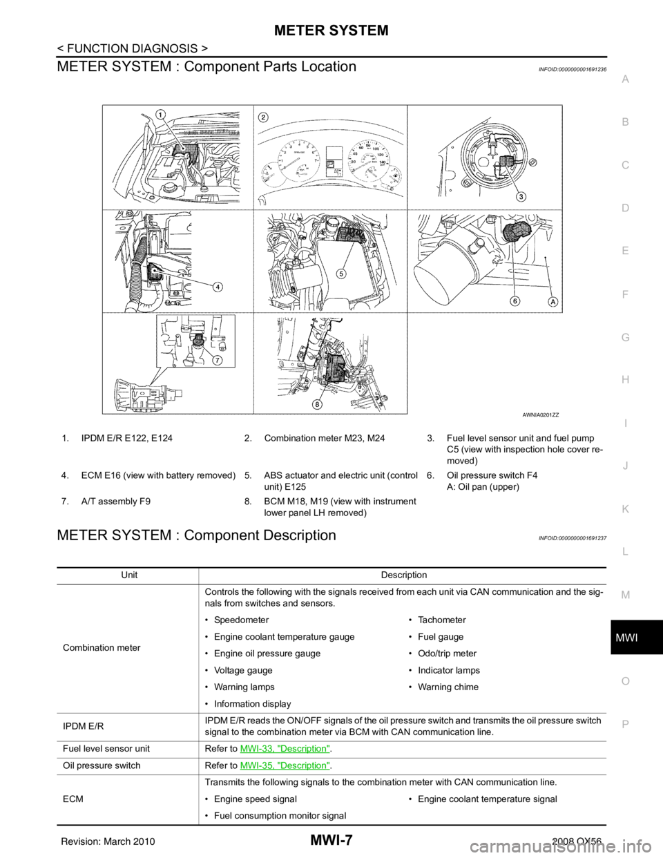
METER SYSTEM : Com ponent Parts LocationINFOID:0000000001691236
METER SYSTEM : Component DescriptionINFOID:0000000001691237
1. IPDM E/R E122, E124 2. Combination meter M23, M24 3. Fuel level sensor unit and fuel pump
C5 (view with inspection hole cover re-
moved)
4. ECM E16 (view with battery removed) 5. ABS actuator and electric unit (control unit) E1256. Oil pressure switch F4
A: Oil pan (upper)
7. A/T assembly F9 8. BCM M18, M19 (view with instrument
lower panel LH removed)
AWNIA0201ZZ
Unit Description
Combination meter Controls the following with the signals received from each unit via CAN communication and the sig-
nals from switches and sensors.
• Speedometer
• Tachometer
• Engine coolant temperature gauge • Fuel gauge
• Engine oil pressure gauge • Odo/trip meter
• Voltage gauge • Indicator lamps
• Warning lamps • Warning chime
• Information display
IPDM E/R IPDM E/R reads the ON/OFF signals of the oil pressure switch and transmits the oil pressure switch
signal to the combination meter via BCM with CAN communication line.
Fuel level sensor unit Refer to MWI-33, "
Description".
Oil pressure switch Refer to MWI-35, "
Description".
ECM Transmits the following signals to the combination meter with CAN communication line.
• Engine speed signal
• Engine coolant temperature signal
• Fuel consumption monitor signal
Revision: March 2010 2008 QX56
Page 2654 of 4083

MWI
METER SYSTEMMWI-9
< FUNCTION DIAGNOSIS >
C
DE
F
G H
I
J
K L
M B A
O P
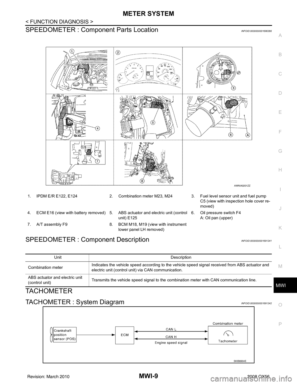
SPEEDOMETER : Compone nt Parts LocationINFOID:0000000001696366
SPEEDOMETER : Component DescriptionINFOID:0000000001691241
TACHOMETER
TACHOMETER : System DiagramINFOID:0000000001691242
1. IPDM E/R E122, E124 2. Combination meter M23, M24 3. Fuel level sensor unit and fuel pump
C5 (view with inspection hole cover re-
moved)
4. ECM E16 (view with battery removed) 5. ABS actuator and electric unit (control unit) E1256. Oil pressure switch F4
A: Oil pan (upper)
7. A/T assembly F9 8. BCM M18, M19 (view with instrument
lower panel LH removed)
AWNIA0201ZZ
Unit Description
Combination meter Indicates the vehicle speed according to the vehicle speed signal received from ABS actuator and
electric unit (control unit) via CAN communication.
ABS actuator and electric unit
(control unit) Transmits the vehicle speed signal to the combination meter with CAN communication line.
SKIB6904E
Revision: March 2010
2008 QX56
Page 2655 of 4083

MWI-10
< FUNCTION DIAGNOSIS >
METER SYSTEM
TACHOMETER : System Description
INFOID:0000000001691243
The tachometer indicates engine speed in revolutions per minute (rpm).
The ECM provides an engine speed signal to the co mbination meter via CAN communication lines.
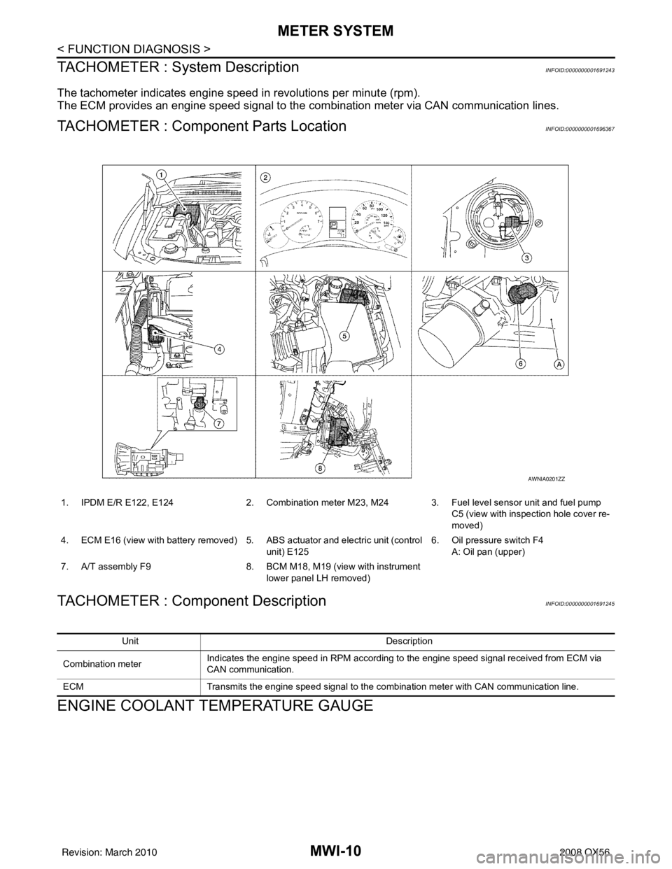
TACHOMETER : Component Parts LocationINFOID:0000000001696367
TACHOMETER : Component DescriptionINFOID:0000000001691245
ENGINE COOLANT TEMPERATURE GAUGE
1. IPDM E/R E122, E1242. Combination meter M23, M24 3. Fuel level sensor unit and fuel pump
C5 (view with inspection hole cover re-
moved)
4. ECM E16 (view with battery removed) 5. ABS actuator and electric unit (control
unit) E125 6. Oil pressure switch F4
A: Oil pan (upper)
7. A/T assembly F9 8. BCM M18, M19 (view with instrument
lower panel LH removed)
AWNIA0201ZZ
Unit Description
Combination meter Indicates the engine speed in RPM according to the engine speed signal received from ECM via
CAN communication.
ECM Transmits the engine speed signal to the combination meter with CAN communication line.
Revision: March 2010 2008 QX56