Page 1948 of 4083
EXL-20
< FUNCTION DIAGNOSIS >
TRAILER TOW
TRAILER TOW
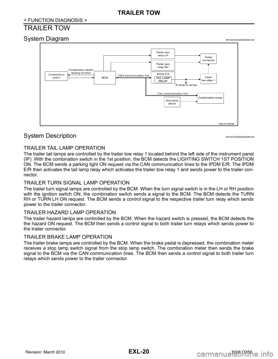
System DiagramINFOID:0000000006095108
System DescriptionINFOID:0000000006095109
TRAILER TAIL LAMP OPERATION
The trailer tail lamps are controlled by the trailer tow relay 1 located behind the left side of the instrument panel
(IP). With the combination switch in the 1st position, the BCM detects the LIGHTING SWITCH 1ST POSITION
ON. The BCM sends a parking light ON request via the CAN communication lines to the IPDM E/R. The IPDM
E/R then activates the tail lamp relay which activates the trailer tow relay 1 and sends power to the trailer con-
nector.
TRAILER TURN SIGNAL LAMP OPERATION
The trailer turn signal lamps are controlled by the BCM. When the turn signal switch is in the LH or RH position
with the ignition switch ON, the combination switch sends a signal to the BCM. The BCM detects the TURN
RH or TURN LH ON request. The BCM sends a control signal to the respective trailer turn relay which sends
power to the trailer connector.
TRAILER HAZARD LAMP OPERATION
The trailer hazard lamps are controlled by the BCM. W hen the hazard switch is pressed, the BCM detects the
the hazard ON request. The BCM then sends a control si gnal to both trailer turn relays which sends power to
the trailer connector.
TRAILER BRAKE LAMP OPERATION
The trailer brake lamps are controlled by the BCM. When the brake pedal is depressed, the combination meter
receives a stop lamp switch signal from the stop lamp switch. The combination meter then sends the brake
signal to the BCM via the CAN communication lines. The BCM then sends a control signal to both trailer turn
relays which sends power to the trailer connector.
AWLIA1764GB
Revision: March 2010 2008 QX56
Page 1949 of 4083
TRAILER TOWEXL-21
< FUNCTION DIAGNOSIS >
C
DE
F
G H
I
J
K
M A
B
EXL
N
O P
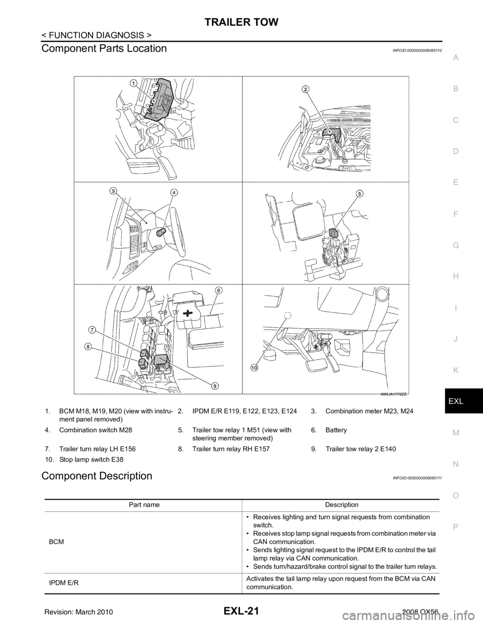
Component Parts LocationINFOID:0000000006095110
Component DescriptionINFOID:0000000006095111
1. BCM M18, M19, M20 (view with instru- ment panel removed) 2. IPDM E/R E119, E122, E123, E124 3. Combination meter M23, M24
4. Combination switch M28 5. Trailer tow relay 1 M51 (view with
steering member removed) 6. Battery
7. Trailer turn relay LH E156 8. Trailer turn relay RH E157 9. Trailer tow relay 2 E140
10. Stop lamp switch E38
AWLIA1772ZZ
Part name Description
BCM • Receives lighting and turn signal requests from combination
switch.
• Receives stop lamp signal requests from combination meter via CAN communication.
• Sends lighting signal request to the IPDM E/R to control the tail
lamp relay via CAN communication.
• Sends turn/hazard/brake control signal to the trailer turn relays.
IPDM E/R Activates the tail lamp relay upon request from the BCM via CAN
communication.
Revision: March 2010
2008 QX56
Page 1950 of 4083
EXL-22
< FUNCTION DIAGNOSIS >
TRAILER TOW
Combination meter• Receives stop lamp switch signal from stop lamp switch.
• Sends stop lamp signal request to the BCM via CAN communi-
cation.
Combination switch Outputs lighting and turn signal requests to the BCM.
Revision: March 2010 2008 QX56
Page 1951 of 4083
DIAGNOSIS SYSTEM (BCM)EXL-23
< FUNCTION DIAGNOSIS >
C
DE
F
G H
I
J
K
M A
B
EXL
N
O P
DIAGNOSIS SYSTEM (BCM)
COMMON ITEM
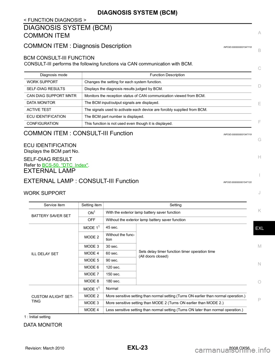
COMMON ITEM : Diagnosis DescriptionINFOID:0000000001547118
BCM CONSULT-III FUNCTION
CONSULT-III performs the following functions via CAN communication with BCM.
COMMON ITEM : CONSULT-III FunctionINFOID:0000000001547119
ECU IDENTIFICATION
Displays the BCM part No.
SELF-DIAG RESULT
Refer to BCS-50, "DTCIndex".
EXTERNAL LAMP
EXTERNAL LAMP : CONSULT-III FunctionINFOID:0000000001547120
WORK SUPPORT
1 : Initial setting
DATA MONITOR
Diagnosis mode Function Description
WORK SUPPORT Changes the setting for each system function.
SELF-DIAG RESULTS Displays the diagnosis results judged by BCM.
CAN DIAG SUPPORT MNTR Monitors the reception status of CAN communication viewed from BCM.
DATA MONITOR The BCM input/output signals are displayed.
ACTIVE TEST The signals used to activate each device are forcibly supplied from BCM.
ECU IDENTIFICATION The BCM pa rt number is displayed.
CONFIGURATION This function is not used even though it is displayed.
Service item Setting item Setting
BATTERY SAVER SET ON
1With the exterior lamp battery saver function
OFF Without the exterior lamp battery saver function
ILL DELAY SET MODE 1
145 sec.
Sets delay timer function timer operation time
(All doors closed)
MODE 2
Without the func-
tion
MODE 3 30 sec.
MODE 4 60 sec.
MODE 5 90 sec.
MODE 6 120 sec.
MODE 7 150 sec.
MODE 8 180 sec.
CUSTOM A/LIGHT SET-
TING MODE 1
1Normal
MODE 2 More sensitive setting than normal setting (Turns ON earlier than normal operation.)
MODE 3 More sensitive setting than MODE 2 (Turns ON earlier than MODE 2.)
MODE 4 Less sensitive setting than normal setting (Turns ON later than normal operation.)
Revision: March 2010 2008 QX56
Page 1952 of 4083
![INFINITI QX56 2008 Factory Service Manual EXL-24
< FUNCTION DIAGNOSIS >
DIAGNOSIS SYSTEM (BCM)
1: The item is indicated, not monitored
ACTIVE TEST
Monitor item[Unit] Description
IGN ON SW
[ON/OFF] The switch status input from ignition switch
INFINITI QX56 2008 Factory Service Manual EXL-24
< FUNCTION DIAGNOSIS >
DIAGNOSIS SYSTEM (BCM)
1: The item is indicated, not monitored
ACTIVE TEST
Monitor item[Unit] Description
IGN ON SW
[ON/OFF] The switch status input from ignition switch](/manual-img/42/57030/w960_57030-1951.png)
EXL-24
< FUNCTION DIAGNOSIS >
DIAGNOSIS SYSTEM (BCM)
1: The item is indicated, not monitored
ACTIVE TEST
Monitor item[Unit] Description
IGN ON SW
[ON/OFF] The switch status input from ignition switch
ACC ON SW
[ON/OFF] The switch status input from ignition switch
TURN SIGNAL R
[ON/OFF]
Each switch status that BCM judges from the combination switch reading function
TURN SIGNAL L
[ON/OFF]
HI BEAM SW
[ON/OFF]
HEAD LAMP SW1
[ON/OFF]
HEAD LAMP SW2
[ON/OFF]
LIGHT SW 1ST
[ON/OFF]
AUTO LIGHT SW
[ON/OFF]
PASSING SW
[ON/OFF]
FR FOG SW
[ON/OFF]
CARGO LAMP SW
[ON/OFF]
RR FOG SW
1
[ON/OFF]
—
DOOR SW-DR
[ON/OFF] The switch status input from front door switch LH
DOOR SW-AS
[ON/OFF] The switch status input from front door switch RH
DOOR SW-RR
[ON/OFF] The switch status input from rear door switch RH
DOOR SW- RL
[ON/OFF] The switch status input from rear door switch LH
DOOR SW-BK
[ON/OFF] The switch status input from the back door switch
OPTICAL SENSOR
[V] The value of exterior brightness voltage input from the optical sensor
Test item
Operation Description
TA I L L A M P ON
Transmits the position light request signal to IPDM E/R via CAN commu-
nication to turn the tail lamp ON.
OFF Stops the tail lamp request signal transmission.
HEAD LAMP HI
Transmits the high beam request signal via CAN communication to turn
the headlamp (HI)
LO Transmits the low beam request signal via CAN communication to turn
the headlamp (LO).
OFF Stops the high & low beam request signal transmission.
Revision: March 2010 2008 QX56
Page 1953 of 4083
DIAGNOSIS SYSTEM (BCM)EXL-25
< FUNCTION DIAGNOSIS >
C
DE
F
G H
I
J
K
M A
B
EXL
N
O P
1: The item is indicated, not monitored.
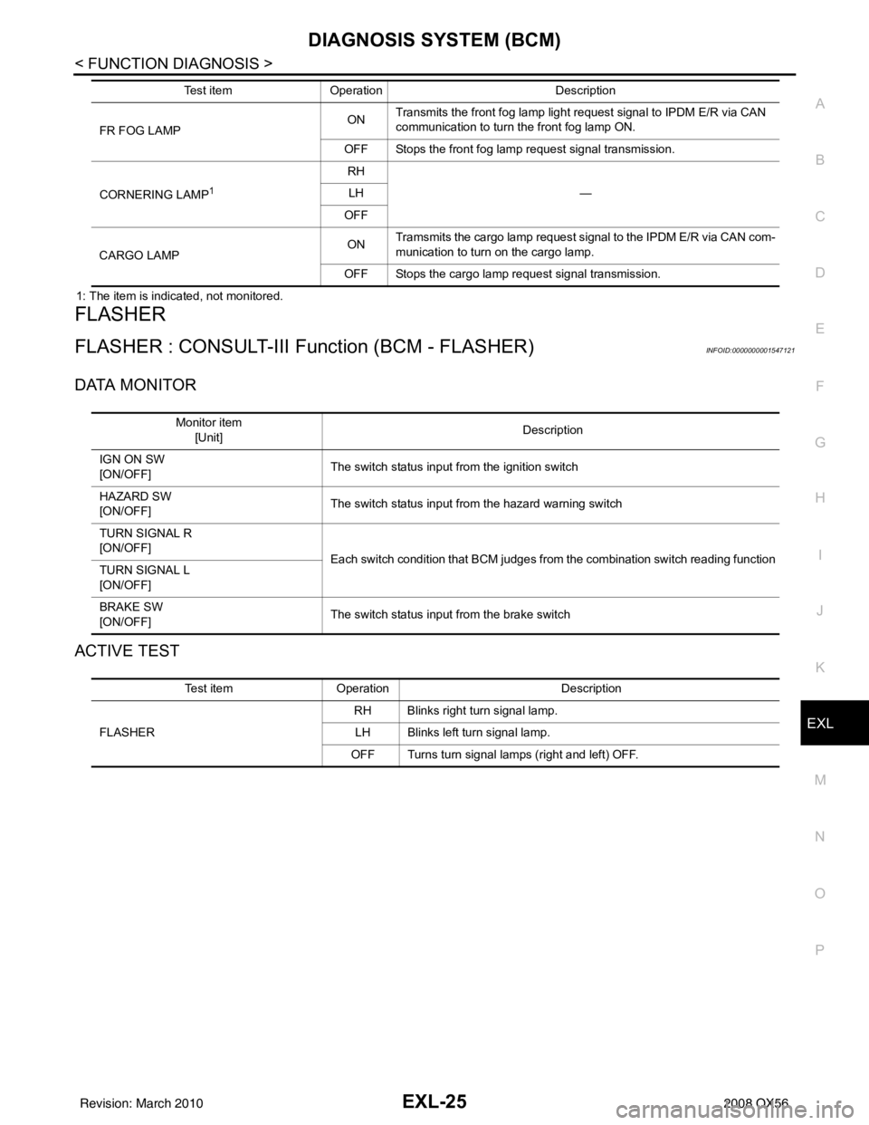
FLASHER
FLASHER : CONSULT-III Function (BCM - FLASHER)INFOID:0000000001547121
DATA MONITOR
ACTIVE TEST
FR FOG LAMP ON
Transmits the front fog lamp light request signal to IPDM E/R via CAN
communication to turn the front fog lamp ON.
OFF Stops the front fog lamp request signal transmission.
CORNERING LAMP
1
RH —
LH
OFF
CARGO LAMP ON
Tramsmits the cargo lamp request signal to the IPDM E/R via CAN com-
munication to turn on the cargo lamp.
OFF Stops the cargo lamp request signal transmission.
Test item
Operation Description
Monitor item
[Unit] Description
IGN ON SW
[ON/OFF] The switch status input from the ignition switch
HAZARD SW
[ON/OFF] The switch status input from the hazard warning switch
TURN SIGNAL R
[ON/OFF] Each switch condition that BCM judges from the combination switch reading function
TURN SIGNAL L
[ON/OFF]
BRAKE SW
[ON/OFF] The switch status input from the brake switch
Test item
Operation Description
FLASHER RH Blinks right turn signal lamp.
LH Blinks left turn signal lamp.
OFF Turns turn signal lamps (right and left) OFF.
Revision: March 2010 2008 QX56
Page 1965 of 4083
TURN SIGNAL LAMP CIRCUITEXL-37
< COMPONENT DIAGNOSIS >
C
DE
F
G H
I
J
K
M A
B
EXL
N
O P
TURN SIGNAL LAMP CIRCUIT
DescriptionINFOID:0000000001547137
The BCM monitors inputs from the combination switch to determine when to activate the turn signals. The
BCM outputs voltage direction to the left and right turn signals during turn signal operation or both during haz-
ard warning operation. The BCM sends a turn signal i ndicator request to the combination meter via the CAN
communication lines.
The BCM performs the fast flasher operation (fail-safe) if any bulb or harness of the turn signal lamp circuit is
open.
NOTE:
Turn signal lamp blinks at normal speed when using the hazard warning lamp.
Component Function CheckINFOID:0000000001547138
1.CHECK TURN SIGNAL LAMP
CONSULT-III
1. Select "FLASHER" of BCM (F LASHER) active test item.
2. With operating the test items, chec k that the turn signal lamp blinks.
Does the turn signal lamp blink?
YES >> Turn signal lamp circuit is normal.
NO >> Refer to EXL-37, "
Diagnosis Procedure".
Diagnosis ProcedureINFOID:0000000001547139
1.CHECK TURN SIGNAL LAMP BULB
Check the applicable lamp bulb to be sure the proper bulb standard is in use and the bulb is not open.
Is the bulb OK?
YES >> GO TO 2
NO >> Replace the bulb.
2.CHECK TURN SIGNAL LA MP OUTPUT VOLTAGE
1. Turn the ignition switch OFF.
2. Disconnect the front turn/fog lamp connector or the rear combi- nation lamp connector.
3. Turn the ignition switch ON.
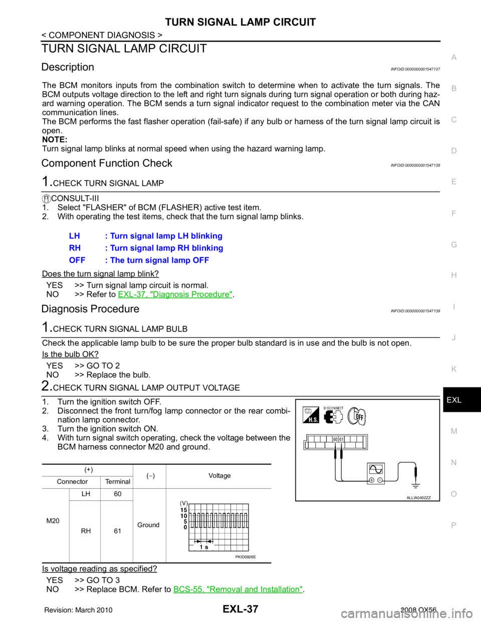
4. With turn signal switch operating, check the voltage between the BCM harness connector M20 and ground.
Is voltage reading as specified?
YES >> GO TO 3
NO >> Replace BCM. Refer to BCS-55, "
Removal and Installation".
LH : Turn signal lamp LH blinking
RH : Turn signal lamp RH blinking
OFF : The turn signal lamp OFF
(+)
(−)V olt a g e
Connector Terminal
M20 LH 60
Ground
RH 61
ALLIA0402ZZ
PKID0926E
Revision: March 2010 2008 QX56
Page 1966 of 4083
EXL-38
< COMPONENT DIAGNOSIS >
TURN SIGNAL LAMP CIRCUIT
3.CHECK TURN SIGNAL LAMP CIRCUIT FOR OPEN
1. Turn the ignition switch OFF.
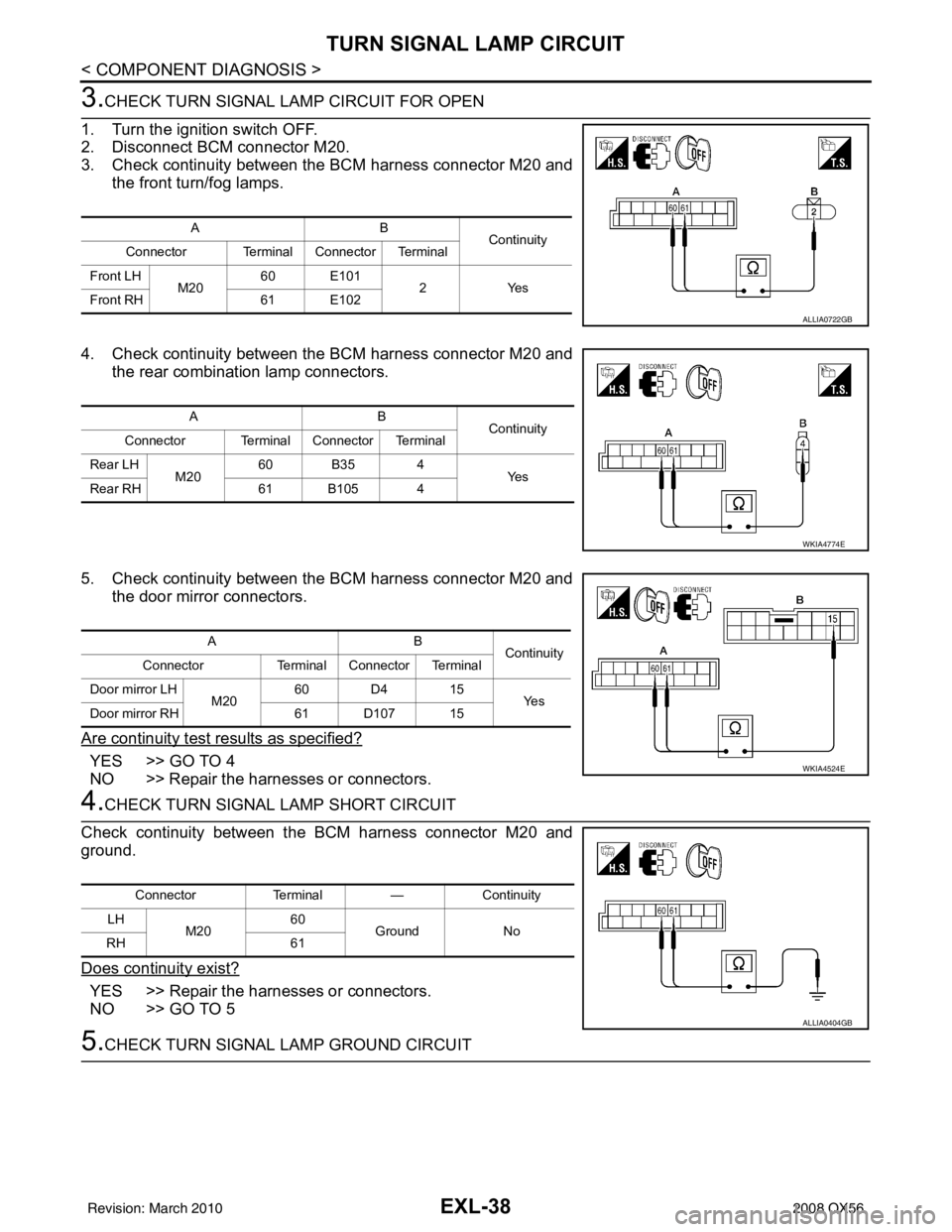
2. Disconnect BCM connector M20.
3. Check continuity between the BCM harness connector M20 and the front turn/fog lamps.
4. Check continuity between the BCM harness connector M20 and the rear combination lamp connectors.
5. Check continuity between the BCM harness connector M20 and the door mirror connectors.
Are continuity test results as specified?
YES >> GO TO 4
NO >> Repair the harnesses or connectors.
4.CHECK TURN SIGNAL LAMP SHORT CIRCUIT
Check continuity between the BCM harness connector M20 and
ground.
Does continuity exist?
YES >> Repair the harnesses or connectors.
NO >> GO TO 5
5.CHECK TURN SIGNAL LAMP GROUND CIRCUIT
AB Continuity
Connector Terminal Connector Terminal
Front LH M2060 E101
2Yes
Front RH 61 E102
ALLIA0722GB
AB
Continuity
Connector Terminal Connector Terminal
Rear LH M2060 B35 4
Ye s
Rear RH 61 B105 4
WKIA4774E
AB
Continuity
Connector Terminal Connector Terminal
Door mirror LH M2060 D4 15
Ye s
Door mirror RH 61 D107 15
WKIA4524E
ConnectorTerminal—Continuity
LH M20 60
Ground No
RH 61
ALLIA0404GB
Revision: March 2010 2008 QX56