2008 INFINITI QX56 brake
[x] Cancel search: brakePage 3736 of 4083
ROAD TESTTM-189
< ON-VEHICLE MAINTENANCE >
CEF
G H
I
J
K L
M A
B
TM
N
O P
ROAD TEST
DescriptionINFOID:0000000001696158
ROAD TEST
• The road test inspects overall performance of the A/T and analyzes possible malfunction causes.
• The road test is carried out in the following three stages.
1. Check before engine is started. Refer to TM-189
.
2. Check at idle. Refer to TM-189
.
3. Cruise test • Inspect all the items from Part 1 to Part 3. Refer to TM-190
, TM-192, TM-193.
• Before beginning the road test, check the test procedure and inspection items.
• Test all inspection items until the symptom is uncov ered. Diagnose NG items when all road tests are com-
plete.
Check Before Engine Is StartedINFOID:0000000001696159
1.CHECK AT CHECK INDICATOR LAMP
1. Park vehicle on level surface.
2. Move selector lever to “P” position.
3. Turn ignition switch to “OFF” position and wait at least 10 seconds.
4. Turn ignition switch to “ON” position. (Do not start engine.)
Does AT CHECK indicator lamp light up for about 2 seconds?
YES >> 1. Turn ignition switch to “OFF” position. 2. Carry out the self-diagnostics and record all NG items on the diagnostics worksheet. Refer toTM-32, "
CONSULT-III Function (TRANSMISSION)".
3. Go to TM-189, "
Check At Idle".
NO >> Stop the road test and go to TM-118, "
A/T Check Indicator Lamp Does Not Come On".
Check At IdleINFOID:0000000001696160
1.CHECK STARTING THE ENGINE
1. Park vehicle on level surface.
2. Move selector lever to “P” or “N” position.
3. Turn ignition switch to “OFF” position.
4. Turn ignition switch to “START” position.
Does the engine start?
YES >> GO TO 2.
NO >> Stop the road test and go to TM-118, "
Engine Cannot Be Started in "P" or "N" Position".
2.CHECK STARTING THE ENGINE
1. Turn ignition switch to “ON” position.
2. Move selector lever in “D”,“4”, “3”, “2”, “1” or “R” position.
3. Turn ignition switch to “START” position.
Does the engine start in either position?
YES >> Stop the road test and go to TM-118, "Engine Cannot Be Started in "P" or "N" Position".
NO >> GO TO 3.
3.CHECK “P” POSITION FUNCTIONS
1. Move selector lever to “P” position.
2. Turn ignition switch to “OFF” position.
3. Release the parking brake.
4. Push the vehicle forward or backward.
5. Engage the parking brake.
When you push the vehicle with disengaging the parking brake, does it move?
Revision: March 2010 2008 QX56
Page 3737 of 4083
TM-190
< ON-VEHICLE MAINTENANCE >
ROAD TEST
YES >> Enter a check mark at “In “P” Position Vehicle Moves When Pushed” on the diagnostics work-sheet, then continue the road test.
NO >> GO TO 4.
4.CHECK “N” POSITION FUNCTIONS
1. Start the engine.
2. Move selector lever to “N” position.
3. Release the parking brake.
Does vehicle move forward or backward?
YES >> Enter a check mark at “In “N” Position Vehicle Moves” on the diagnostics worksheet, then con- tinue the road test.
NO >> GO TO 5.
5.CHECK SHIFT SHOCK
1. Engage the brake.
2. Move selector lever to “D” position.
When the transmission is shifted from
“N” to “D”, is there an excessive shock?
YES >> Enter a check mark at “Large Shock ("N" to "D" Position) on the diagnostics worksheet, then con-
tinue the road test.
NO >> GO TO 6.
6.CHECK “R” POSITION FUNCTIONS
1. Engage the brake.
2. Move selector lever to “R” position.
3. Release the brake for 4 to 5 seconds.
Does the vehicle creep backward?
YES >> GO TO 7.
NO >> Enter a check mark at “Vehicle Does Not Creep Backward In "R" Position” on the diagnostics
worksheet, then continue the road test.
7.CHECK “D” POSITION FUNCTIONS
Inspect whether the vehicle creeps forward when the transmission is put into the “D” position.
Does the vehicle creep forward in the
“D” positions?
YES >> Go to TM-190, "Cruise Test - Part 1", TM-192, "Cruise Test - Part 2", and TM-193, "Cruise Test -
Part 3".
NO >> Enter a check mark at “Vehicle Does Not Cr eep Forward in "D" Position” on the diagnostics work-
sheet, then continue the road test.
Cruise Test - Part 1INFOID:0000000001696161
1.CHECK STARTING OUT FROM D1
1. Drive the vehicle for about 10 minutes to warm up the engine oil and ATF. Appropriate temperature for the ATF: 50 - 80° C (122 - 176°F)
2. Park the vehicle on a level surface.
3. Move selector lever to “P” position.
4. Start the engine.
5. Move selector lever to “D” position.
6. Press the accelerator pedal about half way down to accelerate the vehicle.
With CONSULT-III
Read off the gear positions.
Starts from D1?
YES >> GO TO 2.
NO >> Enter a check mark at “Vehicle Cannot be St arted From D1” on the diagnostics worksheet, then
continue the road test.
2.CHECK SHIFT-UP D1 → D2
Press down the accelerator pedal about half way and inspect if the vehicle shifts up (D1 → D2) at the appropri-
ate speed.
Revision: March 2010 2008 QX56
Page 3739 of 4083

TM-192
< ON-VEHICLE MAINTENANCE >
ROAD TEST
NO >> Enter a check mark at “A/T Does Not Hold Lock-up Condition” on the diagnostics worksheet, thencontinue the road test.
8.CHECK LOCK-UP RELEASE
Check lock-up cancellation by depressing brake pedal lightly to decelerate. With CONSULT-III
Select “TCC SOLENOID 0.00A” with the “MAIN SIGNAL” mode for A/T.
Does lock-up cancel?
YES >> GO TO 9.
NO >> Enter a check mark at “Lock-up Is Not Released” on the diagnostics worksheet, then continue the road test.
9.CHECK SHIFT-DOWN D5 → D4
Decelerate by pressing lightly on the brake pedal. With CONSULT-III
Read the gear position and engine speed.
When the A/T shift-down D5
→ D4, does the engine speed drop smoothly back to idle?
YES >> 1. Stop the vehicle. 2. Go to Cruise test - Part 2 (Refer to AT 58).
NO >> Enter a check mark at “Engine Speed Does Not Return to Idle” on the diagnostics worksheet, then continue the road test. Go to Cruise test - Part 2 (Refer to AT 58).
Cruise Test - Part 2INFOID:0000000001696162
1.CHECK STARTING FROM D1
1. Move selector lever the “D” position.
2. Accelerate at half throttle. With CONSULT-III
Read the gear position.
Does it start from D1?
YES >> GO TO 2.
NO >> Enter a check mark at “Vehicle Cannot Be Started From D1” on the diagnostics worksheet, then continue the road test.
2.CHECK SHIFT-UP D1 → D2
Press the accelerator pedal down all the way and ins pect whether or not the transmission shifts up (D1 → D2)
at the correct speed.
• Refer to TM-291, "
Vehicle Speed at Which Gear Shifting Occurs".
With CONSULT-III
Read the gear position, throttle position and vehicle speed.
Does the A/T shift-up D1
→ D2 at the correct speed?
YES >> GO TO 3.
NO >> Enter a check mark at “Vehicle Does Not Shift: D1 → D2” on the diagnostics worksheet, then con-
tinue the road test.
3.CHECK SHIFT-UP D2 → D3
Press the accelerator pedal down all the way and ins pect whether or not the transmission shifts up (D2 → D3)
at the correct speed.
• Refer to TM-291, "
Vehicle Speed at Which Gear Shifting Occurs".
With CONSULT-III
Read the gear position, throttle position and vehicle speed.
Does the A/T shift-up D2
→ D3 at the correct speed?
YES >> GO TO 4.
NO >> Enter a check mark at “Vehicle Does Not Shift: D2 → D3” on the diagnostics worksheet, then con-
tinue the road test.
4.CHECK SHIFT-UP D3 → D4 AND ENGINE BRAKE
Revision: March 2010 2008 QX56
Page 3740 of 4083
ROAD TESTTM-193
< ON-VEHICLE MAINTENANCE >
CEF
G H
I
J
K L
M A
B
TM
N
O P
When the transmission changes speed D3 → D4, return the accelerator pedal.
Does the A/T shift-up D3
→ D4 and apply the engine brake?
YES >> 1. Stop the vehicle. 2. See TM-193, "
Cruise Test - Part 3".
NO >> Enter a check mark at “Vehicle Does Not Shift: D3 → D4” on the diagnostics worksheet, then con-
tinue the road test.
Cruise Test - Part 3INFOID:0000000001696163
1.CHECK SHIFT-DOWN
During D
5 driving, move gear selector from D → 4 → 3 → 2 → 1.
With CONSULT-III
Read the gear position.
Is downshifting correctly performed?
YES >> GO TO 2.
NO >> Enter a check mark at “Vehicle does not shift” at the corresponding position (5th → 4th, 4th → 3rd,
3rd → 2nd, 2nd → 1st) on the diagnostics worksheet, then continue the road test.
2.CHECK ENGINE BRAKE
Does engine braking effectively reduce speed in 1
1 position?
YES >> 1. Stop the vehicle. 2. Carry out the self-diagnostics. Refer to TM-32, "
CONSULT-III Function (TRANSMISSION)".
NO >> Enter a check mark at “Vehicle Does Not Decelerate By Engine Brake” on the diagnostics work- sheet, then continue trouble diagnosis.
Vehicle Speed When Shifting GearsINFOID:0000000001696164
Refer to TM-193, "Vehicle Speed When Shifting Gears".
Vehicle Speed When Performing and Releasing Complete Lock-upINFOID:0000000001696165
Refer to TM-193, "Vehicle Speed When Performing and Releasing Complete Lock-up".
Revision: March 2010 2008 QX56
Page 3741 of 4083
TM-194
< ON-VEHICLE MAINTENANCE >
A/T POSITION
A/T POSITION
Checking of A/T PositionINFOID:0000000004917429
With the shift selector in the “P” position, turn the ignition switch to the ON position with the engine OFF.
Confirm that the following conditions apply.
• The shift selector can be shifted from the “P ” position only when the brake pedal is depressed.
• The shift selector stops at each position with the feel of engagement when it is moved through all the posi-
tions.
• There is no excessive effort, sticking, noise or rattle.
• The actual position of the shift selector matches the position shown by the shift position indicator and the A/
T body.
• The back-up lamps illuminate only when the shift selector is placed in the “R” position.
• The back-up lamps do not illuminate when the shift selector is pushed against the “R” position when in the
“P” or “N” position.
• The engine can only be started with the shift selector in the “P” and “N” positions.
• The A/T is locked completely when in the “P” position.
Adjustment of A/T PositionINFOID:0000000004917428
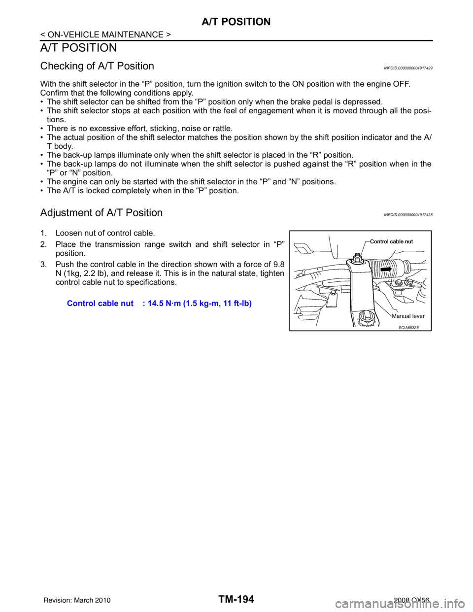
1. Loosen nut of control cable.
2. Place the transmission range switch and shift selector in “P”
position.
3. Push the control cable in the di rection shown with a force of 9.8
N (1kg, 2.2 lb), and release it. This is in the natural state, tighten
control cable nut to specifications.
Control cable nut : 14.5 N·m (1.5 kg-m, 11 ft-lb)
SCIA6532E
Revision: March 2010 2008 QX56
Page 3743 of 4083
TM-196
< ON-VEHICLE REPAIR >
SHIFT CONTROL SYSTEM
Checking of A/T Position
INFOID:0000000004917432
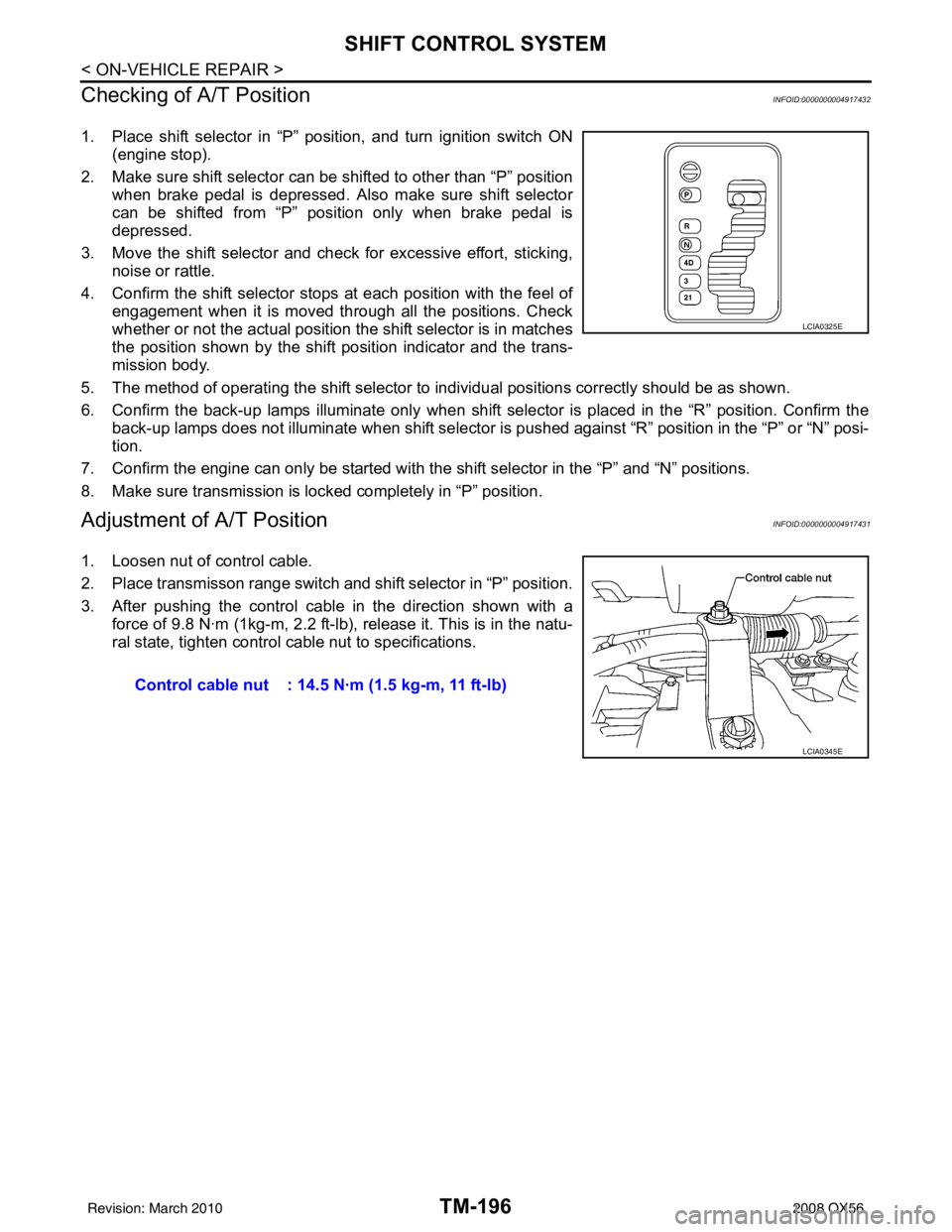
1. Place shift selector in “P” position, and turn ignition switch ON (engine stop).
2. Make sure shift selector can be shifted to other than “P” position when brake pedal is depressed. Also make sure shift selector
can be shifted from “P” position only when brake pedal is
depressed.
3. Move the shift selector and check for excessive effort, sticking, noise or rattle.
4. Confirm the shift selector stop s at each position with the feel of
engagement when it is moved through all the positions. Check
whether or not the actual position the shift selector is in matches
the position shown by the shift position indicator and the trans-
mission body.
5. The method of operating the shift selector to individual positions correctly should be as shown.
6. Confirm the back-up lamps illuminate only when shift sele ctor is placed in the “R” position. Confirm the
back-up lamps does not illuminate when shift selector is pushed against “R” position in the “P” or “N” posi-
tion.
7. Confirm the engine can only be started with the shift selector in the “P” and “N” positions.
8. Make sure transmission is locked completely in “P” position.
Adjustment of A/T PositionINFOID:0000000004917431
1. Loosen nut of control cable.
2. Place transmisson range switch and shift selector in “P” position.
3. After pushing the control cable in the direction shown with a force of 9.8 N·m (1kg-m, 2.2 ft-lb), release it. This is in the natu-
ral state, tighten control cable nut to specifications.
LCIA0325E
Control cable nut : 14.5 N·m (1.5 kg-m, 11 ft-lb)
LCIA0345E
Revision: March 2010 2008 QX56
Page 3754 of 4083
CONTROL VALVE WITH TCMTM-207
< ON-VEHICLE REPAIR >
CEF
G H
I
J
K L
M A
B
TM
N
O P
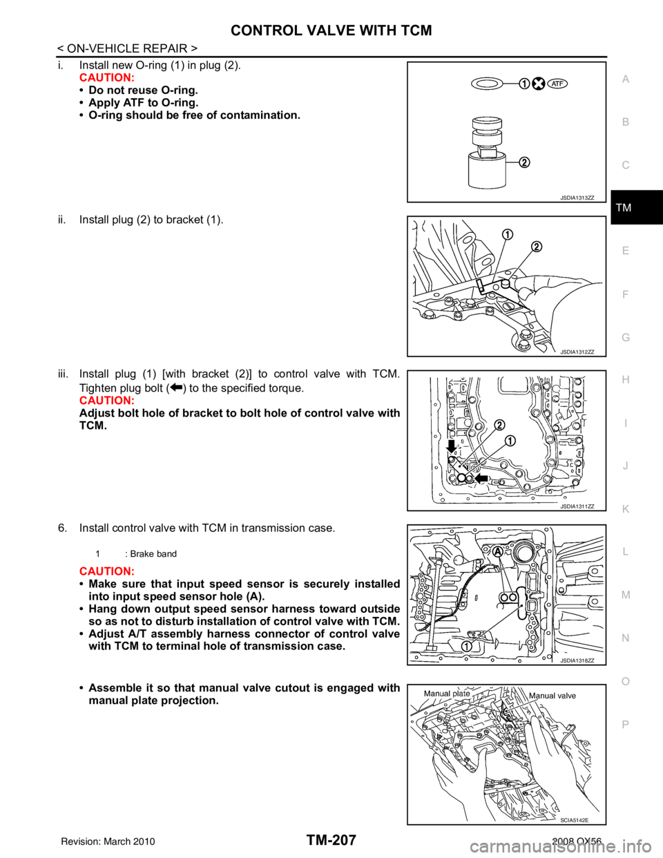
i. Install new O-ring (1) in plug (2). CAUTION:
• Do not reuse O-ring.
• Apply ATF to O-ring.
• O-ring should be free of contamination.
ii. Install plug (2) to bracket (1).
iii. Install plug (1) [with bracket (2)] to control valve with TCM. Tighten plug bolt ( ) to the specified torque.
CAUTION:
Adjust bolt hole of bracket to bolt hole of control valve with
TCM.
6. Install control valve with TCM in transmission case. CAUTION:
• Make sure that input speed sensor is securely installed
into input speed sensor hole (A).
• Hang down output speed sensor harness toward outside
so as not to disturb installati on of control valve with TCM.
• Adjust A/T assembly harness connector of control valve with TCM to terminal hole of transmission case.
• Assemble it so that manual valve cutout is engaged with
manual plate projection.
JSDIA1313ZZ
JSDIA1312ZZ
JSDIA1311ZZ
1 : Brake band
JSDIA1318ZZ
SCIA5142E
Revision: March 2010 2008 QX56
Page 3768 of 4083

OVERHAULTM-221
< DISASSEMBLY AND ASSEMBLY >
CEF
G H
I
J
K L
M A
B
TM
N
O P
: Apply Liquid Gasket (Three Bond 1215) or the equivalent. 1. O-ring
2. Oil pump cover3. O-ring
4. Oil pump housing 5. Self-sealing bolts6. Torque converter
7. Converter housing 8. Oil pump housing oil seal9. Bearing race
10. Needle bearing 11. O-ring 12. Front carrier assembly
13. Needle bearing 14. Snap ring15. Front sun gear
16. 3rd one-way clutch 17. Snap ring18. Bearing race
19. Needle bearing 20. Seal ring 21. Input clutch assembly
22. Needle bearing 23. Rear internal gear24. Brake band
25. Mid carrier assembly 26. Needle bearing 27. Bearing race
28. Rear carrier assembly 29. Needle bearing 30. Mid sun gear
31. Seal ring 32. Rear sun gear33. 1st one-way clutch
34. Snap ring 35. Needle bearing36. High and low reverse clutch hub
37. Snap ring 38. Bearing race39. Needle bearing
Revision: March 2010 2008 QX56