2008 INFINITI QX56 cruise control
[x] Cancel search: cruise controlPage 2539 of 4083
![INFINITI QX56 2008 Factory Service Manual LAN-44
< FUNCTION DIAGNOSIS >[CAN]
CAN COMMUNICATION SYSTEM
FUNCTION DIAGNOSIS
CAN COMMUNICATION SYSTEM
CAN System Specification ChartINFOID:0000000001282400
Determine CAN system type from the followi INFINITI QX56 2008 Factory Service Manual LAN-44
< FUNCTION DIAGNOSIS >[CAN]
CAN COMMUNICATION SYSTEM
FUNCTION DIAGNOSIS
CAN COMMUNICATION SYSTEM
CAN System Specification ChartINFOID:0000000001282400
Determine CAN system type from the followi](/manual-img/42/57030/w960_57030-2538.png)
LAN-44
< FUNCTION DIAGNOSIS >[CAN]
CAN COMMUNICATION SYSTEM
FUNCTION DIAGNOSIS
CAN COMMUNICATION SYSTEM
CAN System Specification ChartINFOID:0000000001282400
Determine CAN system type from the following specificat
ion chart. Then choose the correct diagnosis sheet.
NOTE:
Refer to LAN-14, "
Trouble Diagnosis Procedure" for how to use CAN system specification chart.
×: Applicable
VEHICLE EQUIPMENT IDENTIFICATION INFORMATION
NOTE:
Check CAN system type from the vehicle shape and equipment.
CAN Communication Signal ChartINFOID:0000000001282401
Refer to LAN-13, "How to Use CAN Communication Signal Chart" for how to use CAN communication signal
chart.
NOTE:
Refer to LAN-36, "
Abbreviation List" for the abbreviations of the connecting units.
T: Transmit R: Receive
Body type Wagon
Axle 2WD4WD
Engine VK56DE
Transmission A/T
Brake control VDC
ICC system ××
CAN system type 1234
Diagnosis sheet LAN-40
LAN-41LAN-42LAN-43
AWMIA0012GB
Signal name/Connecting unitECM
TCM
LASER ICC
ADP
AV
BCM
HVAC I-KEY M&A
STRG 4WDABS
IPDM-E
Accelerator pedal position signal T RR R R
A/C compressor request signal T R
ASCD CRUISE lamp signal T R
ASCD OD cancel request signal T R
ASCD operation signal T R
ASCD SET lamp signal T R
Battery voltage signal T R
Closed throttle position signal T RR
Cooling fan speed request signal T R
Engine coolant temperature signal T RR
Revision: March 2010 2008 QX56
Page 2707 of 4083
MWI-62
< ECU DIAGNOSIS >
COMBINATION METER
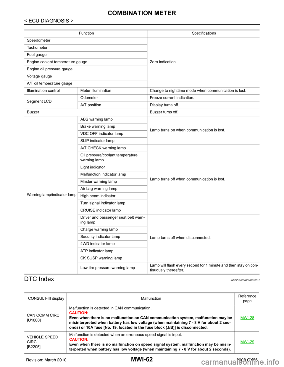
DTC Index
INFOID:0000000001691312
Function Specifications
Speedometer
Zero indication.
Tachometer
Fuel gauge
Engine coolant temperature gauge
Engine oil pressure gauge
Voltage gauge
A/T oil temperature gauge
Illumination control
Meter illumination Change to nighttime mode when communication is lost.
Segment LCD Odometer
Freeze current indication.
A/T position Display turns off.
Buzzer Buzzer turns off.
Warning lamp/indicator lamp ABS warning lamp
Lamp turns on when communication is lost.
Brake warning lamp
VDC OFF indicator lamp
SLIP indicator lamp
A/T CHECK warning lamp
Lamp turns off when communication is lost.
Oil pressure/coolant temperature
warning lamp
Light indicator
Malfunction indicator lamp
Master warning lamp
Air bag warning lamp
High beam indicator
Turn signal indicator lamp
CRUISE indicator lamp
Driver and passenger seat belt warn-
ing lamp
Lamp turns off when disconnected.
Charge warning lamp
Security indicator lamp
4WD indicator lamp
AT P i n d i c a t o r l a m p
CK SUSP warning lamp
Low tire pressure warning lamp
Lamp will flash every second for 1 minute and then stay on con-
tinuously thereafter.
CONSULT-III display
MalfunctionReference
page
CAN COMM CIRC
[U1000] Malfunction is detected in CAN communication.
CAUTION:
Even when there is no malfunction on CAN communication system, malfunction may be
misinterpreted when battery has low voltage (when maintaining 7 - 8 V for about 2 sec-
onds) or 10A fuse [No. 19, located in
the fuse block (J/B)] is disconnected. MWI-28
VEHICLE SPEED
CIRC
[B2205]Malfunction is detected when an erroneous speed signal is input.
CAUTION:
Even when there is no malfunction on speed signal system, malfunction may be misin-
terpreted when battery has lo
w voltage (when maintaining 7 - 8 V for about 2 seconds). MWI-29
Revision: March 2010
2008 QX56
Page 3551 of 4083

TM-4
Precaution for Supplemental Restraint System
(SRS) "AIR BAG" and "SEAT BELT PRE-TEN-
SIONER" ................................................................
173
Precaution Necessary for Steering Wheel Rota-
tion After Battery Disconnect .................................
173
Precaution for On Board Diagnosis (OBD) System
of A/T and Engine ..................................................
174
Precaution .............................................................174
Service Notice or Precaution .................................175
PREPARATION ..........................................176
PREPARATION .............................................. .176
Special Service Tool ............................................ ..176
Commercial Service Tool ......................................177
ON-VEHICLE MAINTENANCE ..................178
A/T FLUID ....................................................... .178
Checking the A/T Fluid (ATF) .............................. ..178
Changing the A/T Fluid (ATF) ................................180
A/T FLUID COOLER ........................................182
A/T Fluid Cooler Cleaning ................................... ..182
Inspection ..............................................................184
STALL TEST ....................................................185
Inspection and Judgment .................................... ..185
LINE PRESSURE TEST ..................................187
Inspection and Judgment .................................... ..187
ROAD TEST .....................................................189
Description ........................................................... ..189
Check Before Engine Is Started ............................189
Check At Idle ....................................................... ..189
Cruise Test - Part 1 ...............................................190
Cruise Test - Part 2 ...............................................192
Cruise Test - Part 3 ...............................................193
Vehicle Speed When Shifting Gears .....................193
Vehicle Speed When Performing and Releasing
Complete Lock-up .................................................
193
A/T POSITION .................................................194
Checking of A/T Position ..................................... ..194
Adjustment of A/T Position ....................................194
ON-VEHICLE REPAIR ...............................195
SHIFT CONTROL SYSTEM ........................... .195
A/T Shift Selector Removal and Installation ..........195
Checking of A/T Position ..................................... ..196
Adjustment of A/T Position ....................................196
AIR BREATHER HOSE ...................................197
Removal and Installation ..................................... ..197
OIL PAN ...........................................................199
Oil Pan ................................................................. .199
CONTROL VALVE WITH TCM ........................201
Control Valve with TCM and A/T Fluid Tempera-
ture Sensor 2 ....................................................... .
201
REAR OIL SEAL ..............................................213
Rear Oil Seal ........................................................ .213
REMOVAL AND INSTALLATION .............214
TRANSMISSION ASSEMBLY ........................ ..214
Removal and Installation (2WD) .......................... .214
Removal and Installation (4WD) ...........................216
DISASSEMBLY AND ASSEMBLY ...........220
OVERHAUL ......................................................220
Component .......................................................... .220
Oil Channel ...........................................................227
Location of Adjusting Shims, Needle Bearings,
Thrust Washers and Snap Rings ......................... .
229
DISASSEMBLY .............................................. ..232
Disassembly ......................................................... .232
REPAIR FOR COMPONENT PARTS ..............250
Oil Pump .............................................................. .250
Front Sun Gear, 3rd One-Way Clutch ...................252
Front Carrier, Input Clutch, Rear Internal Gear .....254
Mid Sun Gear, Rear Sun Gear, High and Low Re-
verse Clutch Hub ................................................. .
259
High and Low Reverse Clutch ..............................264
Direct Clutch .........................................................266
ASSEMBLY .................................................... ..269
Assembly (1) ........................................................ .269
Adjustment ............................................................282
Assembly (2) .........................................................284
SERVICE DATA AND SPECIFICATIONS
(SDS) ........ .................................................
291
SERVICE DATA AND SPECIFICATIONS
(SDS) .............................................................. ..
291
General Specification ........................................... .291
Vehicle Speed at Which Gear Shifting Occurs .....291
Vehicle Speed at Which Lock-up Occurs/Releas-
es ......................................................................... .
291
Stall Speed ............................................................292
Line Pressure ........................................................292
A/T Fluid Temperature Sensor ..............................292
Input Speed Sensor ..............................................292
Output Speed Sensor ...........................................292
Reverse Brake ......................................................292
Total End Play .......................................................292
Torque Converter ..................................................293
Revision: March 2010 2008 QX56
Page 3582 of 4083
DIAGNOSIS SYSTEM (TCM)TM-35
< FUNCTION DIAGNOSIS >
CEF
G H
I
J
K L
M A
B
TM
N
O P
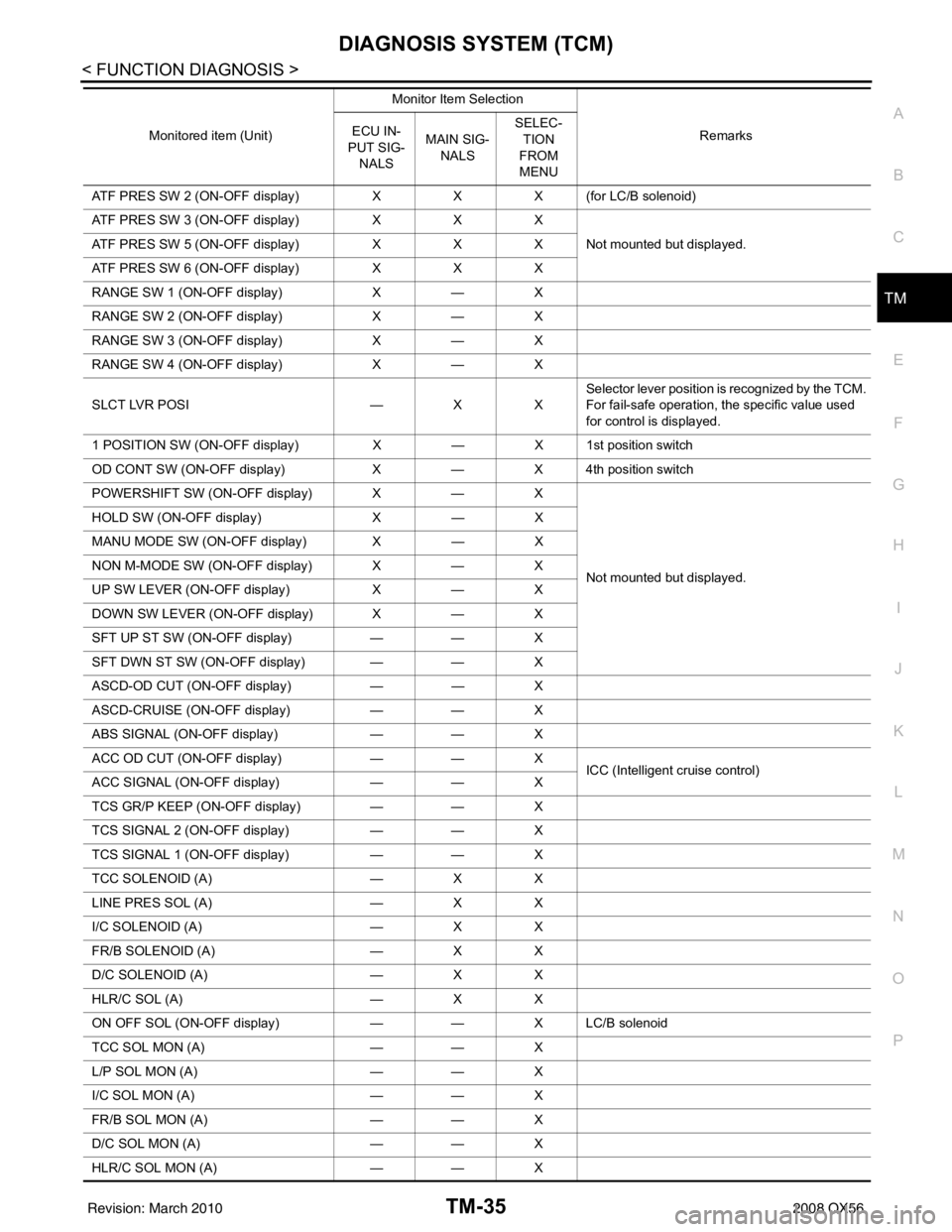
ATF PRES SW 2 (ON-OFF display) XX X (for LC/B solenoid)
ATF PRES SW 3 (ON-OFF display) XX X
Not mounted but displayed.
ATF PRES SW 5 (ON-OFF display) XX X
ATF PRES SW 6 (ON-OFF display) XX X
RANGE SW 1 (ON-OFF display) X— X
RANGE SW 2 (ON-OFF display) X— X
RANGE SW 3 (ON-OFF display) X— X
RANGE SW 4 (ON-OFF display) X— X
SLCT LVR POSI —XXSelector lever position is recognized by the TCM.
For fail-safe operation, the specific value used
for control is displayed.
1 POSITION SW (ON-OFF display) X— X 1st position switch
OD CONT SW (ON-OFF display) X— X 4th position switch
POWERSHIFT SW (ON-OFF display) X —X
Not mounted but displayed.
HOLD SW (ON-OFF display)
X— X
MANU MODE SW (ON-OFF display) X— X
NON M-MODE SW (ON-OFF display) X —X
UP SW LEVER (ON-OFF display) X— X
DOWN SW LEVER (ON-OFF display) X —X
SFT UP ST SW (ON-OFF display) —— X
SFT DWN ST SW (ON-OFF display) — —X
ASCD-OD CUT (ON-OFF display) —— X
ASCD-CRUISE (ON-OFF display) —— X
ABS SIGNAL (ON-OFF display) —— X
ACC OD CUT (ON-OFF display) —— X
ICC (Intelligent cruise control)
ACC SIGNAL (ON-OFF display) —— X
TCS GR/P KEEP (ON-OFF display) —— X
TCS SIGNAL 2 (ON-OFF display) —— X
TCS SIGNAL 1 (ON-OFF display) —— X
TCC SOLENOID (A) —XX
LINE PRES SOL (A) —XX
I/C SOLENOID (A) —XX
FR/B SOLENOID (A) —XX
D/C SOLENOID (A) —XX
HLR/C SOL (A) —XX
ON OFF SOL (ON-OFF display) —— X LC/B solenoid
TCC SOL MON (A) —— X
L/P SOL MON (A) —— X
I/C SOL MON (A) —— X
FR/B SOL MON (A) —— X
D/C SOL MON (A) —— X
HLR/C SOL MON (A) —— X
Monitored item (Unit)
Monitor Item Selection
Remarks
ECU IN-
PUT SIG- NALS MAIN SIG-
NALS SELEC-
TION
FROM
MENU
Revision: March 2010 2008 QX56
Page 3675 of 4083
TM-128
< SYMPTOM DIAGNOSIS >
SYSTEM SYMPTOM
Vehicle Cannot Be Started from D1
INFOID:0000000001604186
SYMPTOM:
Vehicle cannot be started from D1 on cruise test - Part 1.
DIAGNOSTIC PROCEDURE
1.CONFIRM THE SYMPTOM
Check if vehicle creeps in “R” position.
OK or NG
OK >> GO TO 2.
NG >> Refer to TM-123, "
Vehicle Does Not Creep Backward in "R" Position".
2.CHECK SELF-DIAGNOSTIC RESULTS
Perform self-diagnosis. Refer to TM-32, "
CONSULT-III Functi on (TRANSMISSION)".
Is any malfunction detected by self-diagnostic results?
YES >> Check the malfunctioning system.
NO >> GO TO 3.
3.CHECK ACCELERATOR PEDAL POSITION(APP) SENSOR
Check accelerator pedal position (APP) sensor. Refer to TM-69, "
Diagnosis Procedure".
OK or NG
OK >> GO TO 4.
NG >> Repair or replace accelera tor pedal position (APP) sensor.
4.CHECK A/T FLUID LEVEL
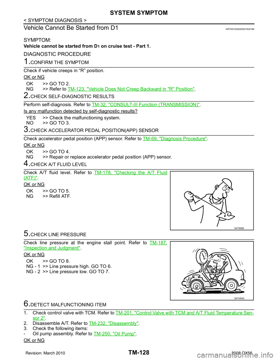
Check A/T fluid level. Refer to TM-178, "
Checking the A/T Fluid
(ATF)".
OK or NG
OK >> GO TO 5.
NG >> Refill ATF.
5.CHECK LINE PRESSURE
Check line pressure at the engine stall point. Refer to TM-187,
"Inspection and Judgment".
OK or NG
OK >> GO TO 8.
NG - 1 >> Line pressure high. GO TO 6.
NG - 2 >> Line pressure low. GO TO 7.
6.DETECT MALFUNCTIONING ITEM
1. Check control valve with TCM. Refer to TM-201, "
Control Valve with TCM and A/T Fluid Temperature Sen-
sor 2".
2. Disassemble A/T. Refer to TM-232, "
Disassembly".
3. Check the following items:
- Oil pump assembly. Refer to TM-250, "
Oil Pump".
OK or NG
SAT638A
SAT494G
Revision: March 2010 2008 QX56
Page 3676 of 4083
SYSTEM SYMPTOMTM-129
< SYMPTOM DIAGNOSIS >
CEF
G H
I
J
K L
M A
B
TM
N
O P
OK >> GO TO 8.
NG >> Repair or replace damaged parts.
7.DETECT MALFUNCTIONING ITEM
1. Check control valve with TCM. Refer to TM-201, "
Control Valve with TCM and A/T Fluid Temperature Sen-
sor 2".
2. Disassemble A/T. Refer to TM-232, "
Disassembly".
3. Check the following items:
- Oil pump assembly. Refer to TM-250, "
Oil Pump".
- Power train system. Refer to TM-232, "
Disassembly".
- Transmission case. Refer to TM-232, "
Disassembly".
OK or NG
OK >> GO TO 8.
NG >> Repair or replace damaged parts.
8.CHECK A/T FLUID CONDITION
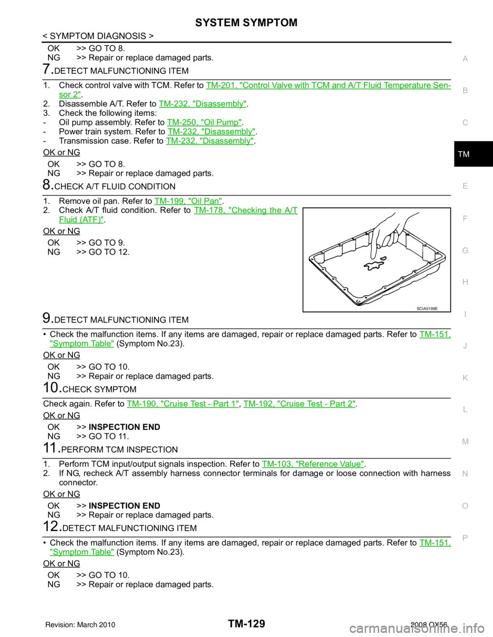
1. Remove oil pan. Refer to TM-199, "
Oil Pan".
2. Check A/T fluid condition. Refer to TM-178, "
Checking the A/T
Fluid (ATF)".
OK or NG
OK >> GO TO 9.
NG >> GO TO 12.
9.DETECT MALFUNCTIONING ITEM
• Check the malfunction items. If any items are damaged, repair or replace damaged parts. Refer to TM-151,
"Symptom Table" (Symptom No.23).
OK or NG
OK >> GO TO 10.
NG >> Repair or replace damaged parts.
10.CHECK SYMPTOM
Check again. Refer to TM-190, "
Cruise Test - Part 1", TM-192, "Cruise Test - Part 2".
OK or NG
OK >> INSPECTION END
NG >> GO TO 11.
11 .PERFORM TCM INSPECTION
1. Perform TCM input/output signals inspection. Refer to TM-103, "
Reference Value".
2. If NG, recheck A/T assembly harness connector terminals for damage or loose connection with harness connector.
OK or NG
OK >> INSPECTION END
NG >> Repair or replace damaged parts.
12.DETECT MALFUNCTIONING ITEM
• Check the malfunction items. If any items are damaged, repair or replace damaged parts. Refer to TM-151,
"Symptom Table" (Symptom No.23).
OK or NG
OK >> GO TO 10.
NG >> Repair or replace damaged parts.
SCIA5199E
Revision: March 2010 2008 QX56
Page 3678 of 4083
SYSTEM SYMPTOMTM-131
< SYMPTOM DIAGNOSIS >
CEF
G H
I
J
K L
M A
B
TM
N
O P
1. Check control valve with TCM. Refer to TM-201, "Control Valve with TCM and A/T Fluid Temperature Sen-
sor 2".
2. Disassemble A/T. Refer to TM-232, "
Disassembly".
3. Check the following items:
- Oil pump assembly. Refer to TM-250, "
Oil Pump".
- Power train system. Refer to TM-232, "
Disassembly".
- Transmission case. Refer to TM-232, "
Disassembly".
OK or NG
OK >> GO TO 7.
NG >> Repair or replace damaged parts.
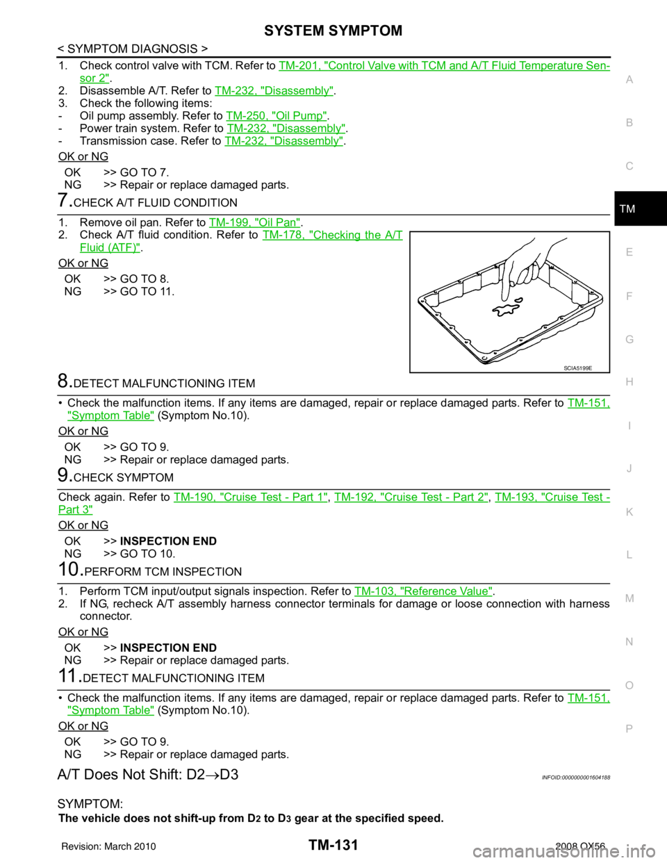
7.CHECK A/T FLUID CONDITION
1. Remove oil pan. Refer to TM-199, "
Oil Pan".
2. Check A/T fluid condition. Refer to TM-178, "
Checking the A/T
Fluid (ATF)".
OK or NG
OK >> GO TO 8.
NG >> GO TO 11.
8.DETECT MALFUNCTIONING ITEM
• Check the malfunction items. If any items are damaged, repair or replace damaged parts. Refer to TM-151,
"Symptom Table" (Symptom No.10).
OK or NG
OK >> GO TO 9.
NG >> Repair or replace damaged parts.
9.CHECK SYMPTOM
Check again. Refer to TM-190, "
Cruise Test - Part 1", TM-192, "Cruise Test - Part 2", TM-193, "Cruise Test -
Part 3"
OK or NG
OK >> INSPECTION END
NG >> GO TO 10.
10.PERFORM TCM INSPECTION
1. Perform TCM input/output signals inspection. Refer to TM-103, "
Reference Value".
2. If NG, recheck A/T assembly harness connector terminals for damage or loose connection with harness connector.
OK or NG
OK >> INSPECTION END
NG >> Repair or replace damaged parts.
11 .DETECT MALFUNCTIONING ITEM
• Check the malfunction items. If any items are damaged, repair or replace damaged parts. Refer to TM-151,
"Symptom Table" (Symptom No.10).
OK or NG
OK >> GO TO 9.
NG >> Repair or replace damaged parts.
A/T Does Not Shift: D2 →D3INFOID:0000000001604188
SYMPTOM:
The vehicle does not shift-up from D2 to D3 gear at the specified speed.
SCIA5199E
Revision: March 2010 2008 QX56
Page 3692 of 4083
SYSTEM SYMPTOMTM-145
< SYMPTOM DIAGNOSIS >
CEF
G H
I
J
K L
M A
B
TM
N
O P
Check the A/T fluid level. Refer to TM-178, "Checking the A/T Fluid
(ATF)".
OK or NG
OK >> GO TO 3.
NG >> Refill ATF.
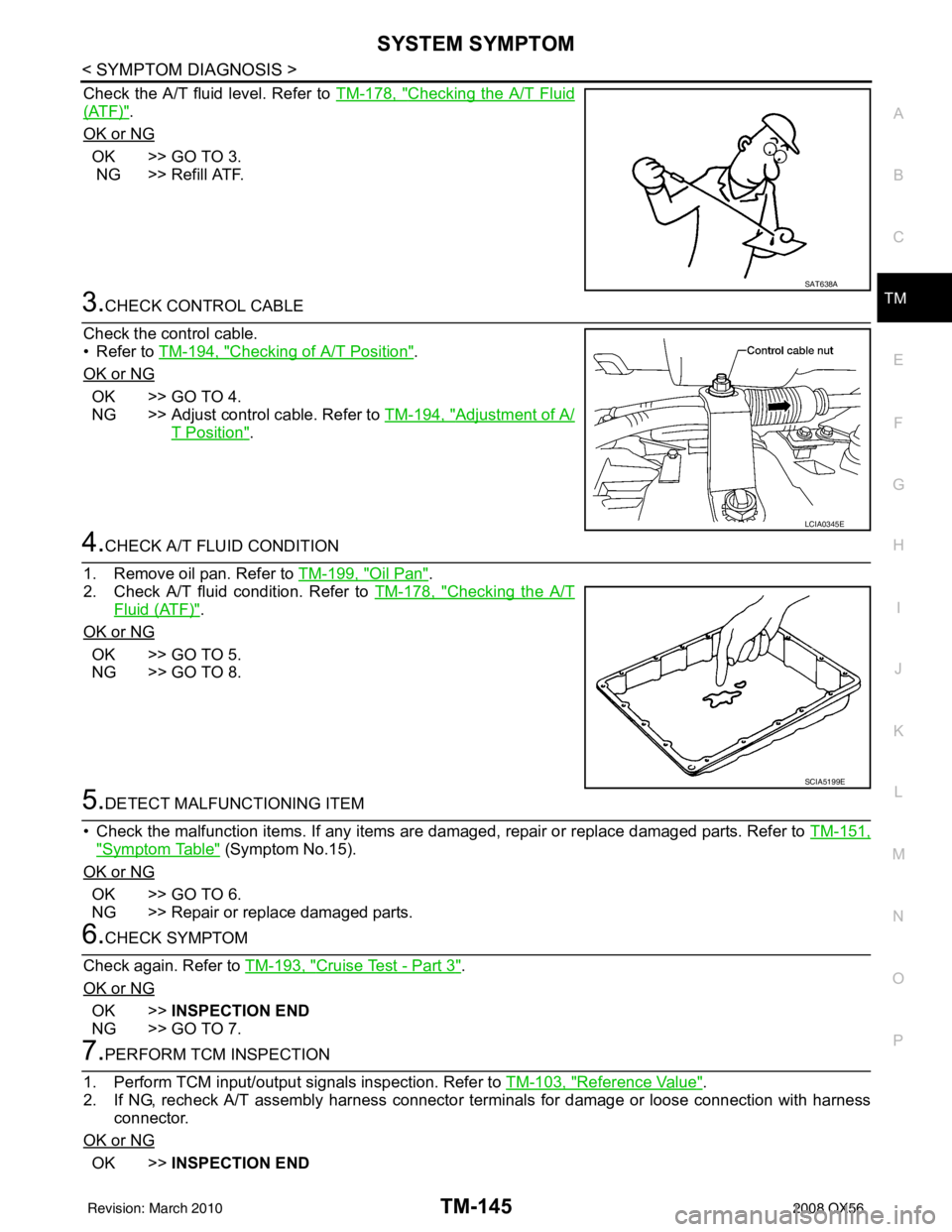
3.CHECK CONTROL CABLE
Check the control cable.
• Refer to TM-194, "
Checking of A/T Position".
OK or NG
OK >> GO TO 4.
NG >> Adjust control cable. Refer to TM-194, "
Adjustment of A/
T Position".
4.CHECK A/T FLUID CONDITION
1. Remove oil pan. Refer to TM-199, "
Oil Pan".
2. Check A/T fluid condition. Refer to TM-178, "
Checking the A/T
Fluid (ATF)".
OK or NG
OK >> GO TO 5.
NG >> GO TO 8.
5.DETECT MALFUNCTIONING ITEM
• Check the malfunction items. If any items are damaged, repair or replace damaged parts. Refer to TM-151,
"Symptom Table" (Symptom No.15).
OK or NG
OK >> GO TO 6.
NG >> Repair or replace damaged parts.
6.CHECK SYMPTOM
Check again. Refer to TM-193, "
Cruise Test - Part 3".
OK or NG
OK >> INSPECTION END
NG >> GO TO 7.
7.PERFORM TCM INSPECTION
1. Perform TCM input/output signals inspection. Refer to TM-103, "
Reference Value".
2. If NG, recheck A/T assembly harness connector terminals for damage or loose connection with harness
connector.
OK or NG
OK >> INSPECTION END
SAT638A
LCIA0345E
SCIA5199E
Revision: March 2010 2008 QX56