2008 INFINITI QX56 wiring
[x] Cancel search: wiringPage 3170 of 4083

SE-48
< ON-VEHICLE REPAIR >
FRONT SEAT
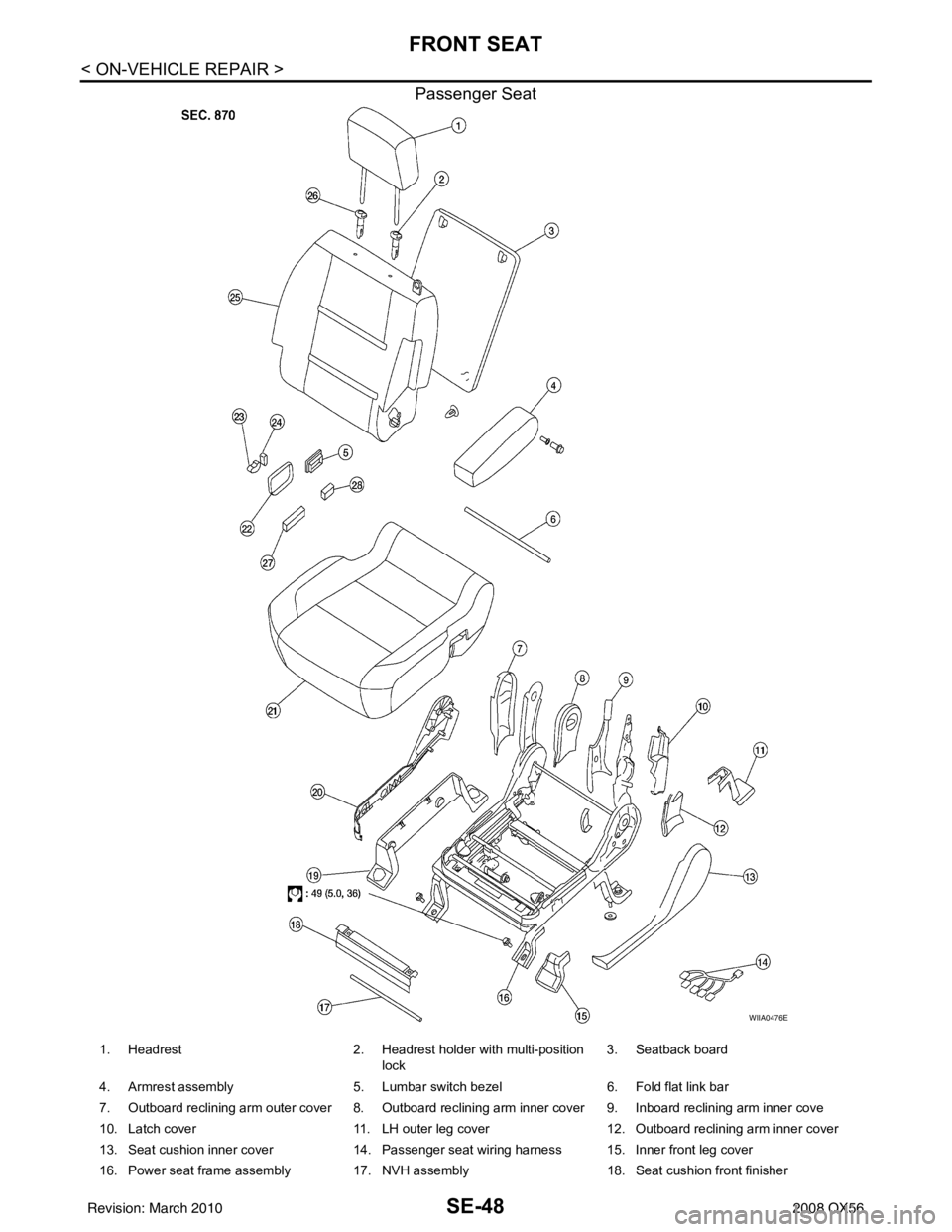
Passenger Seat
WIIA0476E
1. Headrest2. Headrest holder with multi-position
lock 3. Seatback board
4. Armrest assembly 5. Lumbar switch bezel6. Fold flat link bar
7. Outboard reclining arm outer cover 8. Outboard reclining arm inner cover 9. Inboard reclining arm inner cove
10. Latch cover 11. LH outer leg cover12. Outboard reclining arm inner cover
13. Seat cushion inner cover 14. Passenger seat wiring harness 15. Inner front leg cover
16. Power seat frame assembly 17. NVH assembly 18. Seat cushion front finisher
Revision: March 2010 2008 QX56
Page 3186 of 4083

SE-64
< ON-VEHICLE REPAIR >
THIRD SEAT
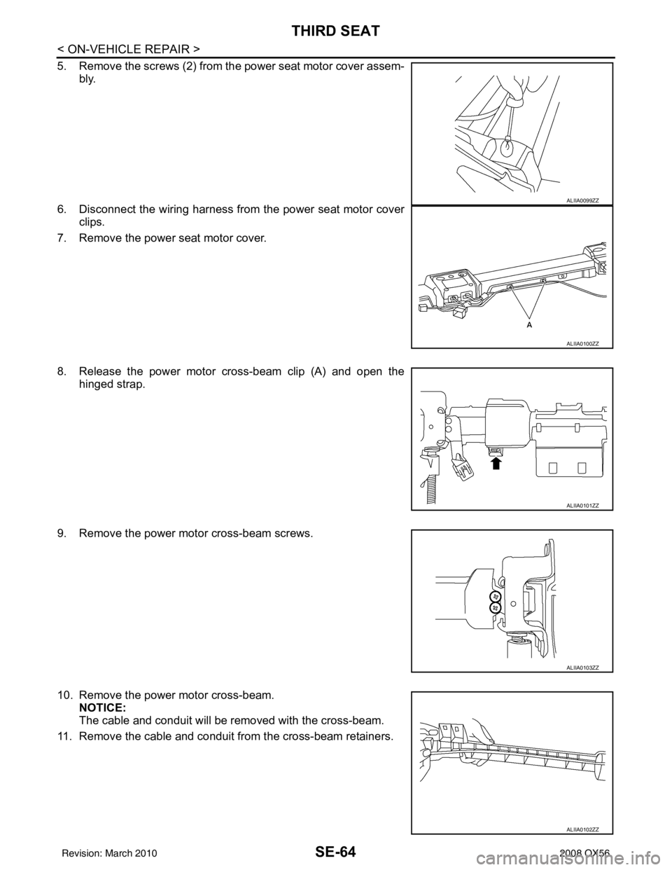
5. Remove the screws (2) from the power seat motor cover assem-bly.
6. Disconnect the wiring harness from the power seat motor cover clips.
7. Remove the power seat motor cover.
8. Release the power motor cross-beam clip (A) and open the hinged strap.
9. Remove the power motor cross-beam screws.
10. Remove the power motor cross-beam. NOTICE:
The cable and conduit will be removed with the cross-beam.
11. Remove the cable and conduit from the cross-beam retainers.
ALIIA0099ZZ
ALIIA0100ZZ
ALIIA0101ZZ
ALIIA0103ZZ
ALIIA0102ZZ
Revision: March 2010 2008 QX56
Page 3191 of 4083

FRONT SEATSE-69
< DISASSEMBLY AND ASSEMBLY >
C
DE
F
G H
I
K L
M A
B
SE
N
O P
1. Headrest 2. Headrest holder with multi-position
lock 3. Seatback assembly
4. Lumbar switch bezel 5. Power seat switch escutcheon 6. Recliner switch knob
7. Slide switch knob 8. Driver power seat frame assembly 9. LH outer leg cover
10. Driver seat wiring harness 11. Bolt cover 12. Seat cushion outer finisher
13. Outer pedestal finisher 14. Seat cushion front finisher15. Seat cushion inner finisher
16. Seat cushion frame 17. Seat cushion heating element 18. Seat cushion pad
19. Seat cushion trim cover 20. Armrest assembly 21. Headrest holder
22. Seat slide/ recline switch 23. Lumbar switch
Revision: March 2010 2008 QX56
Page 3192 of 4083

SE-70
< DISASSEMBLY AND ASSEMBLY >
FRONT SEAT
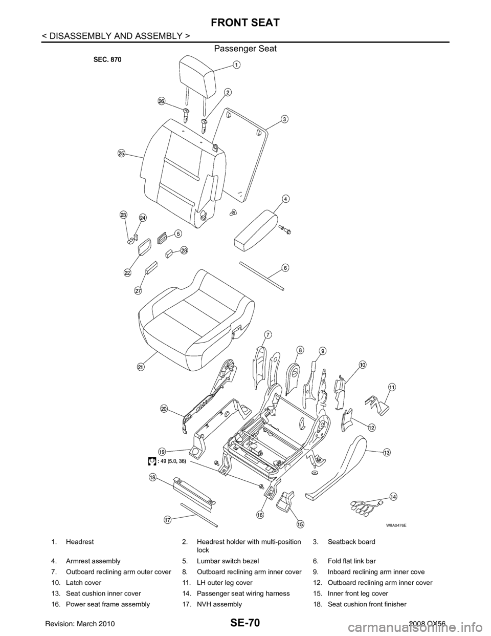
Passenger Seat
WIIA0476E
1. Headrest2. Headrest holder with multi-position
lock 3. Seatback board
4. Armrest assembly 5. Lumbar switch bezel6. Fold flat link bar
7. Outboard reclining arm outer cover 8. Outboard reclining arm inner cover 9. Inboard reclining arm inner cove
10. Latch cover 11. LH outer leg cover12. Outboard reclining arm inner cover
13. Seat cushion inner cover 14. Passenger seat wiring harness 15. Inner front leg cover
16. Power seat frame assembly 17. NVH assembly 18. Seat cushion front finisher
Revision: March 2010 2008 QX56
Page 3210 of 4083

SEC-2
B2191, P1615 DIFFERENCE OF KEY ..............32
Description ..............................................................32
DTC Logic ...............................................................32
Diagnosis Procedure ..............................................32
B2192, P1611 ID DISCORD, IMMU-ECM .........33
Description ........................................................... ...33
DTC Logic ...............................................................33
Diagnosis Procedure ..............................................33
B2193, P1612 CHAIN OF ECM-IMMU ..............35
Description ........................................................... ...35
DTC Logic ...............................................................35
Diagnosis Procedure ..............................................35
B2194 ID DISCORD IMMU-I-KEY .....................36
Description ........................................................... ...36
DTC Logic ...............................................................36
Diagnosis Procedure ..............................................36
B2552 INTELLIGENT KEY ................................37
Description ........................................................... ...37
DTC Logic ...............................................................37
Diagnosis Procedure ..............................................37
Special Repair Requirement ...................................37
B2590 ID DISCORD BCM-I-KEY .................... ...38
Description ........................................................... ...38
DTC Logic ...............................................................38
Diagnosis Procedure ..............................................38
P1610 LOCK MODE ..........................................39
Description ........................................................... ...39
DTC Logic ...............................................................39
Diagnosis Procedure ..............................................39
POWER SUPPLY AND GROUND CIRCUIT .....40
INTELLIGENT KEY UNIT ...................................... ...40
INTELLIGENT KEY UNIT : Diagnosis Procedure ...40
BCM ........................................................................ ...40
BCM : Diagnosis Procedure ...................................40
KEY CYLINDER SWITCH .................................42
Description ........................................................... ...42
Component Function Check ...................................42
Diagnosis Procedure ..............................................42
IGNITION KNOB SWITCH .................................44
Ignition Knob Switch Check ................................. ...44
HOOD SWITCH .................................................46
Diagnosis Procedure ..............................................46
HORN FUNCTION .............................................48
Symptom Table ................................................... ...48
VEHICLE SECURITY INDICATOR ....................49
Description ........................................................... ...49
Component Function Check .................................49
Diagnosis Procedure ............................................ ...49
ECU DIAGNOSIS .......................................51
BCM (BODY CONTROL MODULE) ............... ...51
Reference Value .................................................. ...51
Terminal Layout ......................................................53
Physical Values .......................................................53
Wiring Diagram - VEHICLE SECURITY SYSTEM ...59
Wiring Diagram - IVIS .............................................70
Fail Safe .................................................................78
DTC Inspection Priority Chart ...............................79
DTC Index ..............................................................79
INTELLIGENT KEY UNIT ..................................81
Reference Value - Intelligent Key Unit ................. ...81
Reference Value - Steering Lock Solenoid .............84
Wiring Diagram - INTELLIGENT KEY SYSTEM/
ENGINE START FUNCTION - ................................
85
Fail Safe .................................................................96
DTC Inspection Priority Chart ...............................97
DTC Index ..............................................................97
IPDM E/R (INTELLIGENT POWER DISTRI-
BUTION MODULE ENGINE ROOM) .................
98
Reference Value .................................................. ...98
Terminal Layout ....................................................100
Physical Values .....................................................100
Wiring Diagram .....................................................105
Fail Safe ...............................................................108
DTC Index ............................................................110
SYMPTOM DIAGNOSIS ...........................111
INTELLIGENT KEY SYSTEM/ENGINE
START FUNCTION SYMPTOMS ................... ..
111
Symptom Table .................................................... .111
VEHICLE SECURITY SYSTEM SYMPTOMS ..112
Symptom Table .....................................................112
NISSAN VEHICLE IMMOBILIZER SYSTEM-
NATS SYMPTOMS ...........................................
113
Symptom Table .................................................... .113
PRECAUTION ...........................................114
PRECAUTIONS .............................................. ..114
Precaution for Supplemental Restraint System
(SRS) "AIR BAG" and "SEAT BELT PRE-TEN-
SIONER" .............................................................. .
114
Precaution Necessary for Steering Wheel Rota-
tion After Battery Disconnect ................................
114
ON-VEHICLE REPAIR ..............................116
INTELLIGENT KEY UNIT ............................... ..116
Removal and Installation .......................................116
Revision: March 2010 2008 QX56
Page 3232 of 4083
![INFINITI QX56 2008 Factory Service Manual SEC-24
< COMPONENT DIAGNOSIS >[WITH INTELLIGENT KEY SYSTEM]
U1000 CAN COMM CIRCUIT
COMPONENT DIAGNOSIS
U1000 CAN COMM CIRCUIT
DescriptionINFOID:0000000001539116
CAN (Controller Area Network) is a seri INFINITI QX56 2008 Factory Service Manual SEC-24
< COMPONENT DIAGNOSIS >[WITH INTELLIGENT KEY SYSTEM]
U1000 CAN COMM CIRCUIT
COMPONENT DIAGNOSIS
U1000 CAN COMM CIRCUIT
DescriptionINFOID:0000000001539116
CAN (Controller Area Network) is a seri](/manual-img/42/57030/w960_57030-3231.png)
SEC-24
< COMPONENT DIAGNOSIS >[WITH INTELLIGENT KEY SYSTEM]
U1000 CAN COMM CIRCUIT
COMPONENT DIAGNOSIS
U1000 CAN COMM CIRCUIT
DescriptionINFOID:0000000001539116
CAN (Controller Area Network) is a serial communication
line for real time applications. It is an on-vehicle mul-
tiplex communication line with high data communication speed and excellent error detection ability. Modern
vehicle is equipped with many electronic control unit, and each control unit shares information and links with
other control units during operation (not independent). In CAN communication, control units are connected
with 2 communication lines (CAN-H line, CAN-L line) al lowing a high rate of information transmission with less
wiring. Each control unit transmits/receives data but selectively reads required data only.
CAN Communication Signal Chart, refer to LAN-44, "
CAN Communication Signal Chart".
DTC LogicINFOID:0000000001539117
DTC DETECTION LOGIC
Diagnosis ProcedureINFOID:0000000001539118
1.PERFORM SELF DIAGNOSTIC
1. Turn ignition switch ON and wait for 2 seconds or more.
2. Check “Self Diagnostic Result”.
Is
“CAN COMM CIRCUIT” displayed?
YES >> Refer to LAN-5, "CAN Communication Control Circuit".
NO >> Refer to GI-38, "
Intermittent Incident".
DTCCONSULT-III display
description DTC Detection Condition
Possible cause
U1000 CAN COMM CIRCUIT When Intelligent Key unit cannot communi-
cate CAN communication signal continuous-
ly for 2 seconds or more. In CAN communication system, any item (or items)
of the following listed below is malfunctioning.
•Transmission
• Receiving (BCM)
• Receiving (ECM)
• Receiving (METER/M&A)
Revision: March 2010
2008 QX56
Page 3233 of 4083
![INFINITI QX56 2008 Factory Service Manual U1010 CONTROL UNIT (CAN)SEC-25
< COMPONENT DIAGNOSIS > [WITH INTELLIGENT KEY SYSTEM]
C
D
E
F
G H
I
J
L
M A
B
SEC
N
O P
U1010 CONTROL UNIT (CAN)
DescriptionINFOID:0000000001539119
CAN (Controller Area INFINITI QX56 2008 Factory Service Manual U1010 CONTROL UNIT (CAN)SEC-25
< COMPONENT DIAGNOSIS > [WITH INTELLIGENT KEY SYSTEM]
C
D
E
F
G H
I
J
L
M A
B
SEC
N
O P
U1010 CONTROL UNIT (CAN)
DescriptionINFOID:0000000001539119
CAN (Controller Area](/manual-img/42/57030/w960_57030-3232.png)
U1010 CONTROL UNIT (CAN)SEC-25
< COMPONENT DIAGNOSIS > [WITH INTELLIGENT KEY SYSTEM]
C
D
E
F
G H
I
J
L
M A
B
SEC
N
O P
U1010 CONTROL UNIT (CAN)
DescriptionINFOID:0000000001539119
CAN (Controller Area Network) is a serial communication line for real time applications. It is an on-vehicle mul-
tiplex communication line with high data communicati on speed and excellent error detection ability. Modern
vehicle is equipped with many electronic control unit, and each control unit shares information and links with
other control units during operation (not independent). In CAN communication, control units are connected
with 2 communication lines (CAN-H line, CAN-L line) allowing a high rate of information transmission with less
wiring. Each control unit transmits/receives data but selectively reads required data only.
CAN Communication Signal Chart, refer to LAN-44, "
CAN Communication Signal Chart".
DTC LogicINFOID:0000000001539120
DTC DETECTION LOGIC
Diagnosis ProcedureINFOID:0000000001539121
1.REPLACE INTELLIGENT KEY UNIT
When DTC [U1010] is detected, replace Intelligent Key unit.
>> Replace Intelligent Key unit.
Special Repair RequirementINFOID:0000000001539122
1.REQUIRED WORK WHEN REPLACING INTELLIGENT KEY UNIT
Initialize control unit. Refer to CONSULT-III Operation Manual.
>> Work end.
DTC CONSULT-III display de-
scription DTC Detection Condit
ion Possible cause
U1010 CONTROL UNIT (CAN) When detecting error during the initial diagnosis of CAN control-
ler of Intelligent Key unit. Intelligent Key unit
Revision: March 2010
2008 QX56
Page 3267 of 4083
![INFINITI QX56 2008 Factory Service Manual BCM (BODY CONTROL MODULE)SEC-59
< ECU DIAGNOSIS > [WITH INTELLIGENT KEY SYSTEM]
C
D
E
F
G H
I
J
L
M A
B
SEC
N
O P
Wiring Diagram - VE HICLE SECURITY SYSTEMINFOID:0000000001539162
AWKWA0023GB
Revision: INFINITI QX56 2008 Factory Service Manual BCM (BODY CONTROL MODULE)SEC-59
< ECU DIAGNOSIS > [WITH INTELLIGENT KEY SYSTEM]
C
D
E
F
G H
I
J
L
M A
B
SEC
N
O P
Wiring Diagram - VE HICLE SECURITY SYSTEMINFOID:0000000001539162
AWKWA0023GB
Revision:](/manual-img/42/57030/w960_57030-3266.png)
BCM (BODY CONTROL MODULE)SEC-59
< ECU DIAGNOSIS > [WITH INTELLIGENT KEY SYSTEM]
C
D
E
F
G H
I
J
L
M A
B
SEC
N
O P
Wiring Diagram - VE HICLE SECURITY SYSTEMINFOID:0000000001539162
AWKWA0023GB
Revision: March 2010 2008 QX56