2008 INFINITI QX56 service
[x] Cancel search: servicePage 1877 of 4083
EM-74
< ON-VEHICLE REPAIR >
CYLINDER HEAD
VALVE GUIDE REPLACEMENT
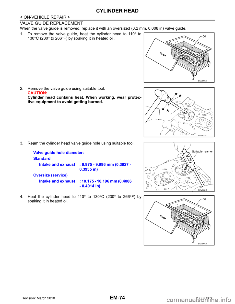
When the valve guide is removed, replace it with an oversized (0.2 mm, 0.008 in) valve guide.
1. To remove the valve guide, heat the cylinder head to 110° to
130° C (230° to 266°F) by soaking it in heated oil.
2. Remove the valve guide using suitable tool. CAUTION:
Cylinder head contains heat. When working, wear protec-
tive equipment to avo id getting burned.
3. Ream the cylinder head valve guide hole using suitable tool.
4. Heat the cylinder head to 110 ° to 130° C (230° to 266° F) by
soaking it in heated oil.
SEM008A
SEM931C
Valve guide hole diameter:
Standard
Intake and exhaust : 9.975 - 9.996 mm (0.3927 - 0.3935 in)
Oversize (service) Intake and exhaust : 10.175 - 10.196 mm (0.4006 - 0.4014 in)
SEM932C
SEM008A
Revision: March 2010 2008 QX56
Page 1878 of 4083
CYLINDER HEADEM-75
< ON-VEHICLE REPAIR >
C
DE
F
G H
I
J
K L
M A
EM
NP
O
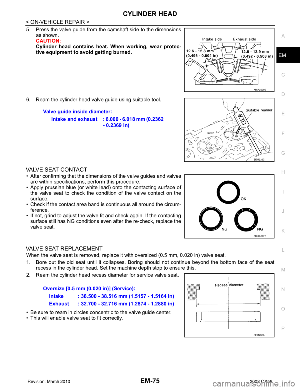
5. Press the valve guide from the camshaft side to the dimensions
as shown.
CAUTION:
Cylinder head contains heat . When working, wear protec-
tive equipment to avo id getting burned.
6. Ream the cylinder head valve guide using suitable tool.
VALVE SEAT CONTACT
• After confirming that the dimensions of the valve guides and valves are within specifications, perform this procedure.
• Apply prussian blue (or white lead) onto the contacting surface of the valve seat to check the condition of the valve contact on the
surface.
• Check if the contact area band is continuous all around the circum- ference.
• If not, grind to adjust the valve fi t and check again. If the contacting
surface still has NG conditions even after the re-check, replace the
valve seat.
VALVE SEAT REPLACEMENT
When the valve seat is removed, replace it with oversized (0.5 mm, 0.020 in) valve seat.
1. Bore out the old seat until it collapses. Boring should not continue beyond the bottom face of the seat recess in the cylinder head. Set the machine depth stop to ensure this.
2. Ream the cylinder head recess diameter for service valve seat.
• Be sure to ream in circles concentric to the valve guide center.
• This will enable valve seat to fit correctly.
KBIA2530E
Valve guide inside diameter:
Intake and exhaust : 6.000 - 6.018 mm (0.2362 - 0.2369 in)
SEM932C
SBIA0322E
Oversize [0.5 mm (0.020 in)] (Service):
Intake : 38.500 - 38.516 mm (1.5157 - 1.5164 in)
Exhaust : 32.700 - 32.716 mm (1.2874 - 1.2880 in)
SEM795A
Revision: March 2010 2008 QX56
Page 1895 of 4083
EM-92
< DISASSEMBLY AND ASSEMBLY >
ENGINE UNIT
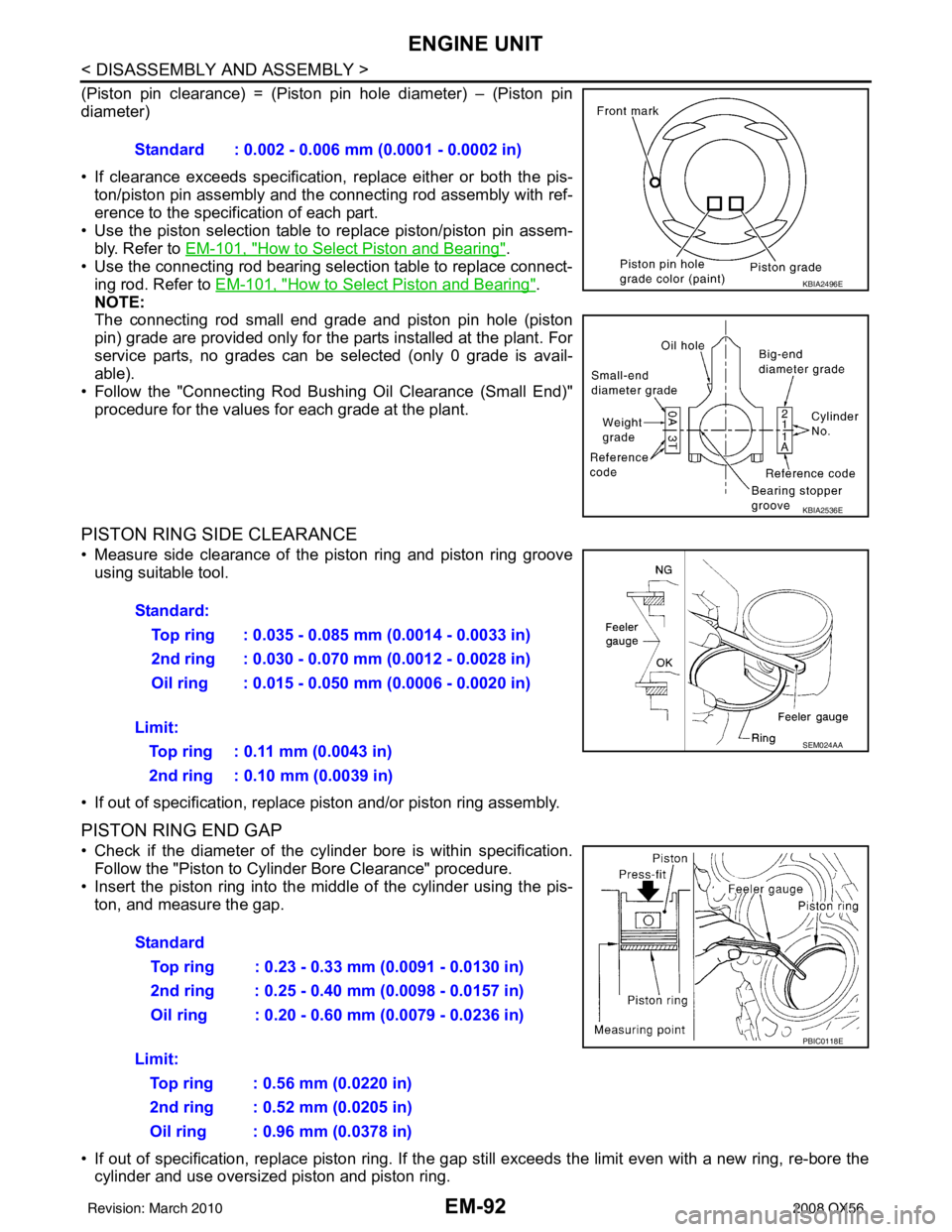
(Piston pin clearance) = (Piston pin hole diameter) – (Piston pin
diameter)
• If clearance exceeds specification, replace either or both the pis-
ton/piston pin assembly and the connecting rod assembly with ref-
erence to the specification of each part.
• Use the piston selection table to replace piston/piston pin assem-
bly. Refer to EM-101, "
How to Select Piston and Bearing".
• Use the connecting rod bearing selection table to replace connect- ing rod. Refer to EM-101, "
How to Select Piston and Bearing".
NOTE:
The connecting rod small end grade and piston pin hole (piston
pin) grade are provided only for the parts installed at the plant. For
service parts, no grades can be selected (only 0 grade is avail-
able).
• Follow the "Connecting Rod Bushing Oil Clearance (Small End)" procedure for the values for each grade at the plant.
PISTON RING SIDE CLEARANCE
• Measure side clearance of the piston ring and piston ring grooveusing suitable tool.
• If out of specification, replac e piston and/or piston ring assembly.
PISTON RING END GAP
• Check if the diameter of the cyli nder bore is within specification.
Follow the "Piston to Cylinder Bore Clearance" procedure.
• Insert the piston ring into the middle of the cylinder using the pis- ton, and measure the gap.
• If out of specification, replace pi ston ring. If the gap still exceeds the li mit even with a new ring, re-bore the
cylinder and use oversized piston and piston ring. Standard : 0.002 - 0.006 mm (0.0001 - 0.0002 in)
KBIA2496E
KBIA2536E
Standard:
Top ring : 0.035 - 0.085 mm (0.0014 - 0.0033 in)
2nd ring : 0.030 - 0.070 mm (0.0012 - 0.0028 in)
Oil ring : 0.015 - 0.050 mm (0.0006 - 0.0020 in)
Limit: Top ring : 0.11 mm (0.0043 in)
2nd ring : 0.10 mm (0.0039 in)
SEM024AA
Standard Top ring : 0.23 - 0.33 mm (0.0091 - 0.0130 in)
2nd ring : 0.25 - 0.40 mm (0.0098 - 0.0157 in)
Oil ring : 0.20 - 0.60 mm (0.0079 - 0.0236 in)
Limit: Top ring : 0.56 mm (0.0220 in)
2nd ring : 0.52 mm (0.0205 in)
Oil ring : 0.96 mm (0.0378 in)
PBIC0118E
Revision: March 2010 2008 QX56
Page 1904 of 4083
HOW TO SELECT PISTON AND BEARINGEM-101
< DISASSEMBLY AND ASSEMBLY >
C
DE
F
G H
I
J
K L
M A
EM
NP
O
HOW TO SELECT PISTON AND BEARING
How to Select Piston and BearingINFOID:0000000001538834
DESCRIPTION
*For the service parts, the grade for fitting cannot be selected between a piston pin and a connecting rod.
(Only 0 grade is available.) The information at the sh
ipment from the plant is described as a reference.
• The identification grade stamped on each part is the grade for the dimension measured in new condition.
This grade cannot apply to reused parts.
• For reused or repaired parts, measure the dimens ion accurately. Determine the grade by comparing the
measurement with the values of each selection table.
• For details of the measurement method of each part , the reuse standards, and the selection method of the
selective fitting parts, follow the applicable procedures.
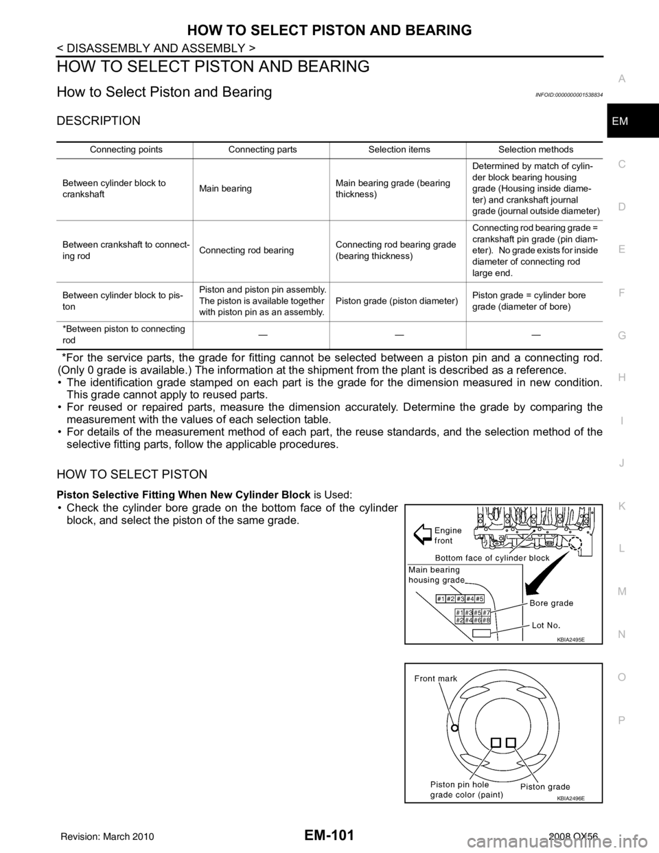
HOW TO SELECT PISTON
Piston Selective Fitting When New Cylinder Block is Used:
• Check the cylinder bore grade on the bottom face of the cylinder
block, and select the piston of the same grade.
Connecting points Connecting parts Selection itemsSelection methods
Between cylinder block to
crankshaft Main bearing Main bearing grade (bearing
thickness)Determined by match of cylin-
der block bearing housing
grade (Housing inside diame-
ter) and crankshaft journal
grade (journal outside diameter)
Between crankshaft to connect-
ing rod Connecting rod bearing Connecting rod bearing grade
(bearing thickness)Connecting rod bearing grade =
crankshaft pin grade (pin diam-
eter). No grade exists for inside
diameter of connecting rod
large end.
Between cylinder block to pis-
ton Piston and piston pin assembly.
The piston is available together
with piston pin as an assembly.
Piston grade (piston diameter)
Piston grade = cylinder bore
grade (diameter of bore)
*Between piston to connecting
rod ———
KBIA2495E
KBIA2496E
Revision: March 2010
2008 QX56
Page 1905 of 4083
EM-102
< DISASSEMBLY AND ASSEMBLY >
HOW TO SELECT PISTON AND BEARING
When Cylinder Block is Reused
1. Measure cylinder block bore diameter.
2. Determine the bore grade by comparing the measurement with the values under the “Cylinder bore diam-
eter” of the piston selection table.
Piston Selection Table
Unit: mm (in)
NOTE:
• The piston is available together with piston pin as an assembly.
• The piston pin (piston pin bore) grade is provided only for the parts installed at the plant. For service parts, no grades can be selected (only 0 grade is available).
• Hone the cylinder to obtain specified clearance between the piston and cylinder bore.
HOW TO SELECT CONNECTING ROD BEARING
When New Connecting Rod and Crankshaft are Used
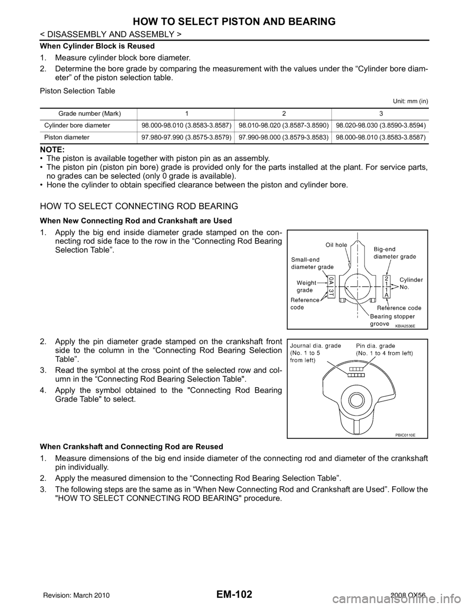
1. Apply the big end inside diameter grade stamped on the con- necting rod side face to the row in the “Connecting Rod Bearing
Selection Table”.
2. Apply the pin diameter grade stamped on the crankshaft front side to the column in the “Connecting Rod Bearing Selection
Table”.
3. Read the symbol at the cross point of the selected row and col-
umn in the “Connecting Rod Bearing Selection Table".
4. Apply the symbol obtained to the "Connecting Rod Bearing Grade Table" to select.
When Crankshaft and Connecting Rod are Reused
1. Measure dimensions of the big end inside diameter of the connecting rod and diameter of the crankshaftpin individually.
2. Apply the measured dimension to the “Connecting Rod Bearing Selection Table”.
3. The following steps are the same as in “When New Connecting Rod and Crankshaft are Used”. Follow the "HOW TO SELECT CONNECTING ROD BEARING" procedure.
Grade number (Mark) 12 3
Cylinder bore diameter 98.000-98.010 (3.8583-3.8587) 98.010-98.020 (3.8587-3.8590) 98.020-98.030 (3.8590-3.8594)
Piston diameter 97.980-97.990 (3.8575-3.8579) 97.990-98.000 (3.8579-3.8583) 98.000-98.010 (3.8583-3.8587)
KBIA2536E
PBIC0110E
Revision: March 2010 2008 QX56
Page 1907 of 4083
EM-104
< DISASSEMBLY AND ASSEMBLY >
HOW TO SELECT PISTON AND BEARING
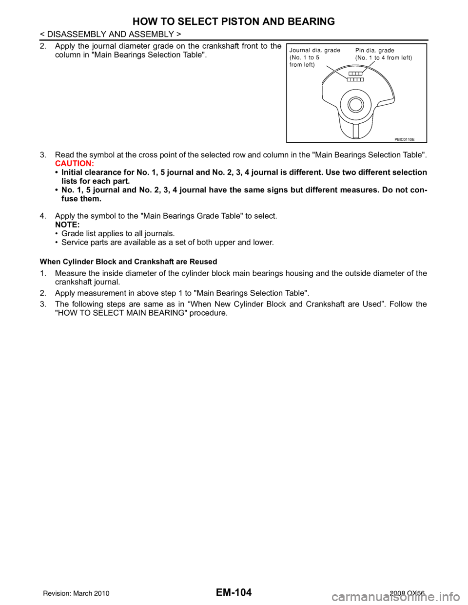
2. Apply the journal diameter grade on the crankshaft front to thecolumn in "Main Bearings Selection Table".
3. Read the symbol at the cross point of the selected row and column in the "Main Bearings Selection Table".
CAUTION:
• Initial clearance for No. 1, 5 journal and No. 2, 3, 4 journal is different. Use two different selection
lists for each part.
• No. 1, 5 journal and No. 2, 3, 4 journal have the same signs but different measures. Do not con-
fuse them.
4. Apply the symbol to the "Main Bearings Grade Table" to select. NOTE:
• Grade list applies to all journals.
• Service parts are available as a set of both upper and lower.
When Cylinder Block and Crankshaft are Reused
1. Measure the inside diameter of the cylinder block main bearings housing and the outside diameter of the
crankshaft journal.
2. Apply measurement in above step 1 to "Main Bearings Selection Table".
3. The following steps are same as in “When New Cylinder Block and Crankshaft are Used”. Follow the "HOW TO SELECT MAIN BEARING" procedure.
PBIC0110E
Revision: March 2010 2008 QX56
Page 1911 of 4083
EM-108
< SERVICE DATA AND SPECIFICATIONS (SDS)
SERVICE DATA AND SPECIFICATIONS (SDS)
SERVICE DATA AND SPECIFICATIONS (SDS)
SERVICE DATA AND SPECIFICATIONS (SDS)
Standard and LimitINFOID:0000000001538835
GENERAL SPECIFICATIONS
DRIVE BELTS
EXHAUST MANIFOLD
Cylinder arrangementV- 8
Displacement cm
3(in3) 5,552 (338.80)
Bore and stroke mm (in) 98 x 92 (3.86 x 3.62)
Valve arrangement DOHC
Firing order 1-8-7-3-6-5-4-2
Number of piston rings Compression
2
Oil 1
Number of main bearings 5
Compression ratio 9.8:1
C o m p r e s s i o n p r e s s u r e k P a
(kg/cm
2, psi)/rpm Standard
1,520 (15.5, 220)/200
Minimum 1,324 (13.5, 192)/200
Differential limit between cylinders 98 (1.0, 14)/200
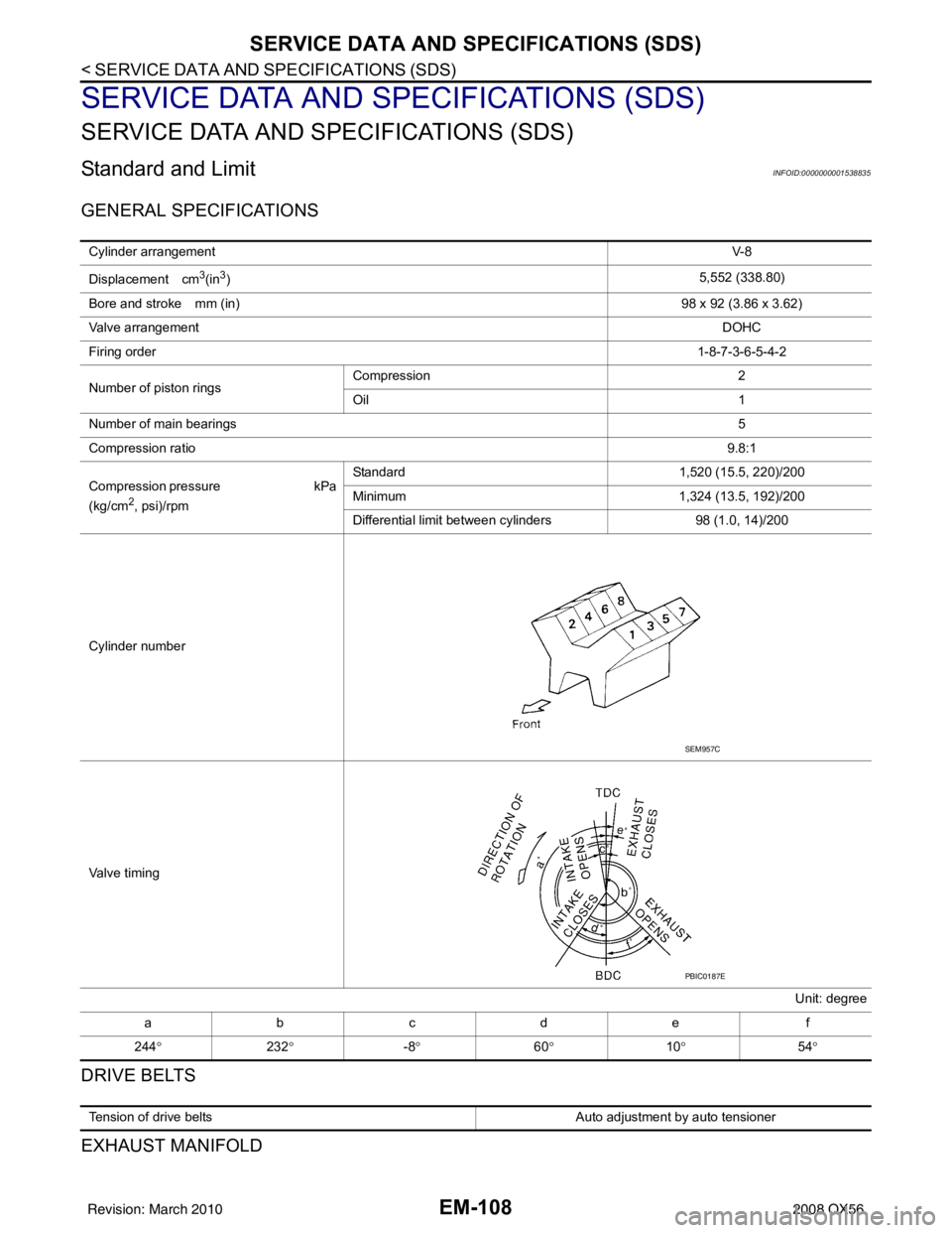
Cylinder number
Valve timing Unit: degree
abcde f
244 ° 232° -8° 60° 10° 54°
SEM957C
PBIC0187E
Tension of drive belts Auto adjustment by auto tensioner
Revision: March 2010 2008 QX56
Page 1912 of 4083
SERVICE DATA AND SPECIFICATIONS (SDS)EM-109
< SERVICE DATA AND SPECIFICATIONS (SDS)
C
DE
F
G H
I
J
K L
M A
EM
NP
O
Unit: mm (in)
SPARK PLUG
Unit: mm (in)
*: Always check with the Parts Department for the latest parts information.
CAMSHAFT AND CAMSHAFT BEARING
Unit: mm (in)
*: Total indicator reading
Valve Seal
Unit: mm (in)
Valve Lifter
Unit: mm (in)
Valve Clearance
Items
Limit
Surface distortion Exhaust manifold 0.3 (0.012)
Make NGK
Model Standard model
Standard type* DILFR5A-11
Gap (Nominal) 1.1 (0.043)
ItemsStandard
Camshaft runout [TIR*] Less than 0.02 (0.0008)
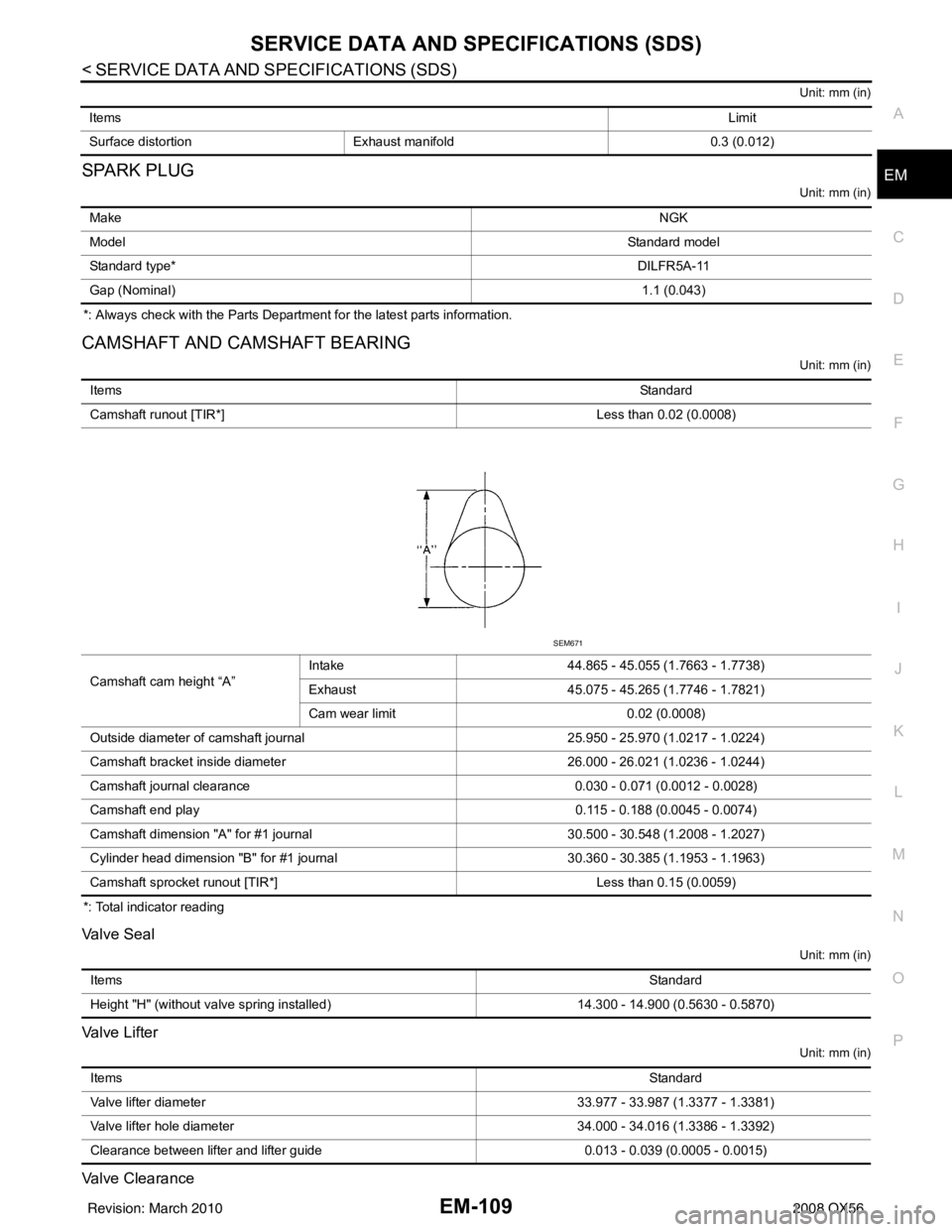
Camshaft cam height “A” Intake
44.865 - 45.055 (1.7663 - 1.7738)
Exhaust 45.075 - 45.265 (1.7746 - 1.7821)
Cam wear limit 0.02 (0.0008)
Outside diameter of camshaft journal 25.950 - 25.970 (1.0217 - 1.0224)
Camshaft bracket inside diameter 26.000 - 26.021 (1.0236 - 1.0244)
Camshaft journal clearance 0.030 - 0.071 (0.0012 - 0.0028)
Camshaft end play 0.115 - 0.188 (0.0045 - 0.0074)
Camshaft dimension "A" for #1 journal 30.500 - 30.548 (1.2008 - 1.2027)
Cylinder head dimension "B" for #1 journal 30.360 - 30.385 (1.1953 - 1.1963)
Camshaft sprocket runout [TIR*] Less than 0.15 (0.0059)
SEM671
Items Standard
Height "H" (without valve spring installed) 14.300 - 14.900 (0.5630 - 0.5870)
Items Standard
Valve lifter diameter 33.977 - 33.987 (1.3377 - 1.3381)
Valve lifter hole diameter 34.000 - 34.016 (1.3386 - 1.3392)
Clearance between lifter and lifter guide 0.013 - 0.039 (0.0005 - 0.0015)
Revision: March 2010 2008 QX56