2008 INFINITI QX56 seats
[x] Cancel search: seatsPage 3037 of 4083
SUNROOF SYSTEMRF-53
< ON-VEHICLE REPAIR >
C
DE
F
G H
I
J
L
M A
B
RF
N
O P
CAUTION:
• Before removal, fully close the glass lid assembly. Then, after removal, do not move the motor
assembly.
• After installing or adjusting the sunroof and glass lid, check gap alignment and sunroof operation to
prevent malfunction.
• Handle glass lid with care so not to cause damage.
Removal and InstallationINFOID:0000000001536769
CAUTION:
• Always work with a helper.
• When taking sunroof unit out, use shop cloths to protect the seats and trim from damage.
• After installing the sunroof unit or glass lid, be sure to check gap adjustment to prevent any mal-
function.
SUNROOF UNIT
NOTE:
• For easier installation, mark each point before removal.
Removal
1. Remove headlining. Refer to INT-17, "Removal and Installation".
2. Remove the sunroof glass lid. Refer to RF-53, "
Removal and Installation".
3. Remove overhead console bracket.
4. Disconnect the drain hoses.
5. Remove front sunroof bolts.
6. Remove rear sunroof bracket bolts.
7. Remove the side bolts and the sunroof unit.
Installation
1. Position the sunroof frame assembly and install the side bolts.
2. Install the rear brackets.
3. Install the front sunroof frame assembly bolts.
4. Connect drain hoses.
5. Install the overhead console bracket.
6. Install the sunroof glass lid. Refer to RF-52, "
Exploded View".
7. Install headlining. Refer to INT-17, "
Removal and Installation".
8. Perform initialization procedure. Refer to RF-5, "
ADDITIONAL SERVICE WHEN REPLACING CONTROL
UNIT : Special Repair Requirement".
GLASS LID
Removal
1. Open sunshade.
2. Ensure glass lid is closed.
3. Remove side cover LH and RH.
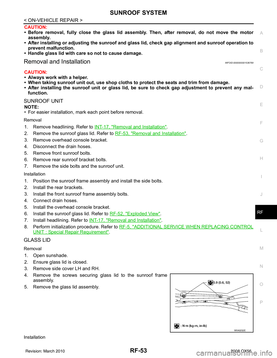
4. Remove the screws securing glass lid to the sunroof frame assembly.
5. Remove the glass lid assembly.
Installation
WIIA0252E
Revision: March 2010 2008 QX56
Page 3053 of 4083
RSU-14
< REMOVAL AND INSTALLATION >
REAR SUSPENSION MEMBER
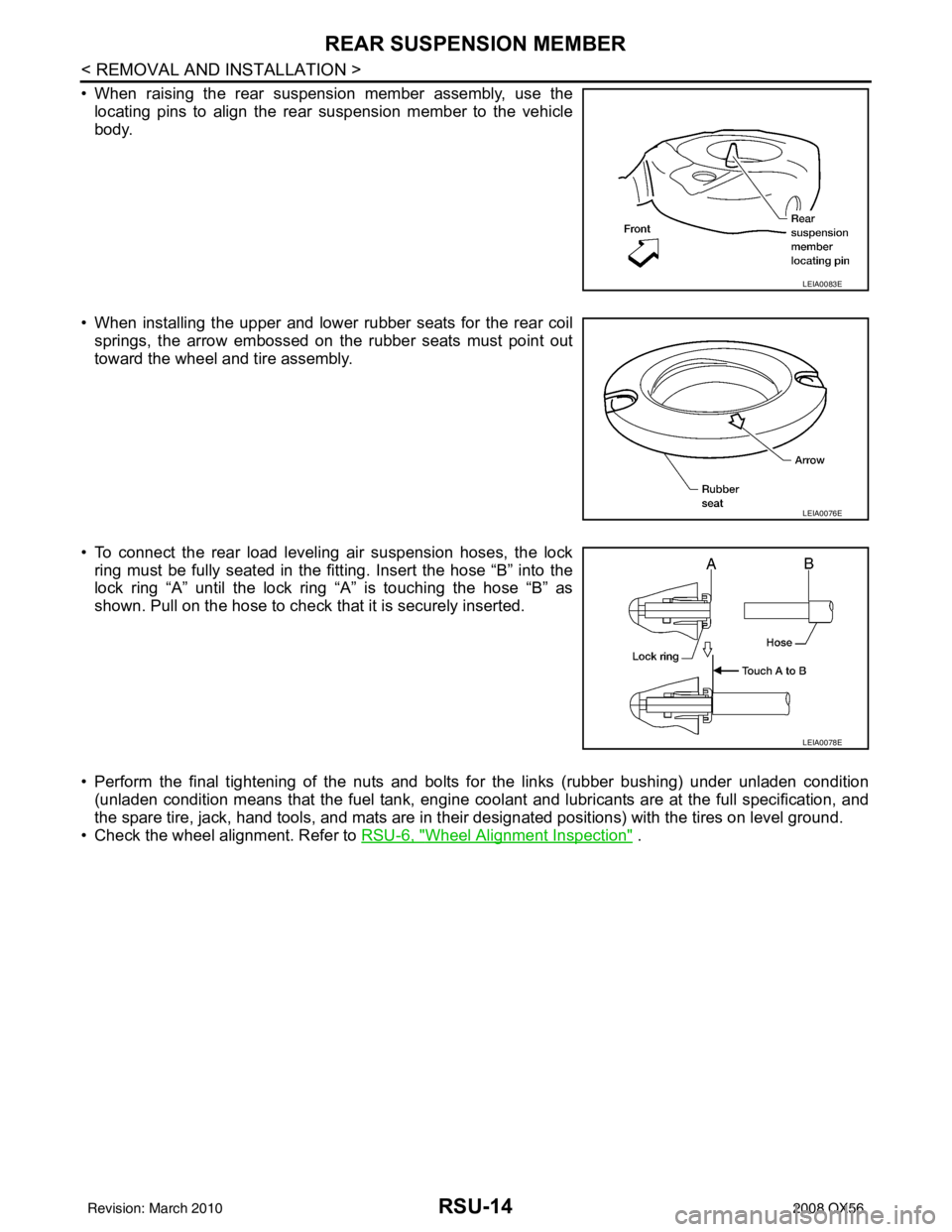
• When raising the rear suspension member assembly, use thelocating pins to align the rear suspension member to the vehicle
body.
• When installing the upper and lower rubber seats for the rear coil springs, the arrow embossed on the rubber seats must point out
toward the wheel and tire assembly.
• To connect the rear load leveling air suspension hoses, the lock ring must be fully seated in the fitt ing. Insert the hose “B” into the
lock ring “A” until the lock ring “A” is touching the hose “B” as
shown. Pull on the hose to check that it is securely inserted.
• Perform the final tightening of the nuts and bolts for the links (rubber bushing) under unladen condition (unladen condition means that the fuel tank, engine cool ant and lubricants are at the full specification, and
the spare tire, jack, hand tools, and mats are in t heir designated positions) with the tires on level ground.
• Check the wheel alignment. Refer to RSU-6, "
Wheel Alignment Inspection" .
LEIA0083E
LEIA0076E
LEIA0078E
Revision: March 2010 2008 QX56
Page 3060 of 4083
REAR LOWER LINK & COIL SPRINGRSU-21
< REMOVAL AND INSTALLATION >
C
DF
G H
I
J
K L
M A
B
RSU
N
O P
8. Slowly lower the suitable jack to release the coil spring tension. Then remove the upper rubber seat, coil spring, and lower rubber seat from the rear lower link.
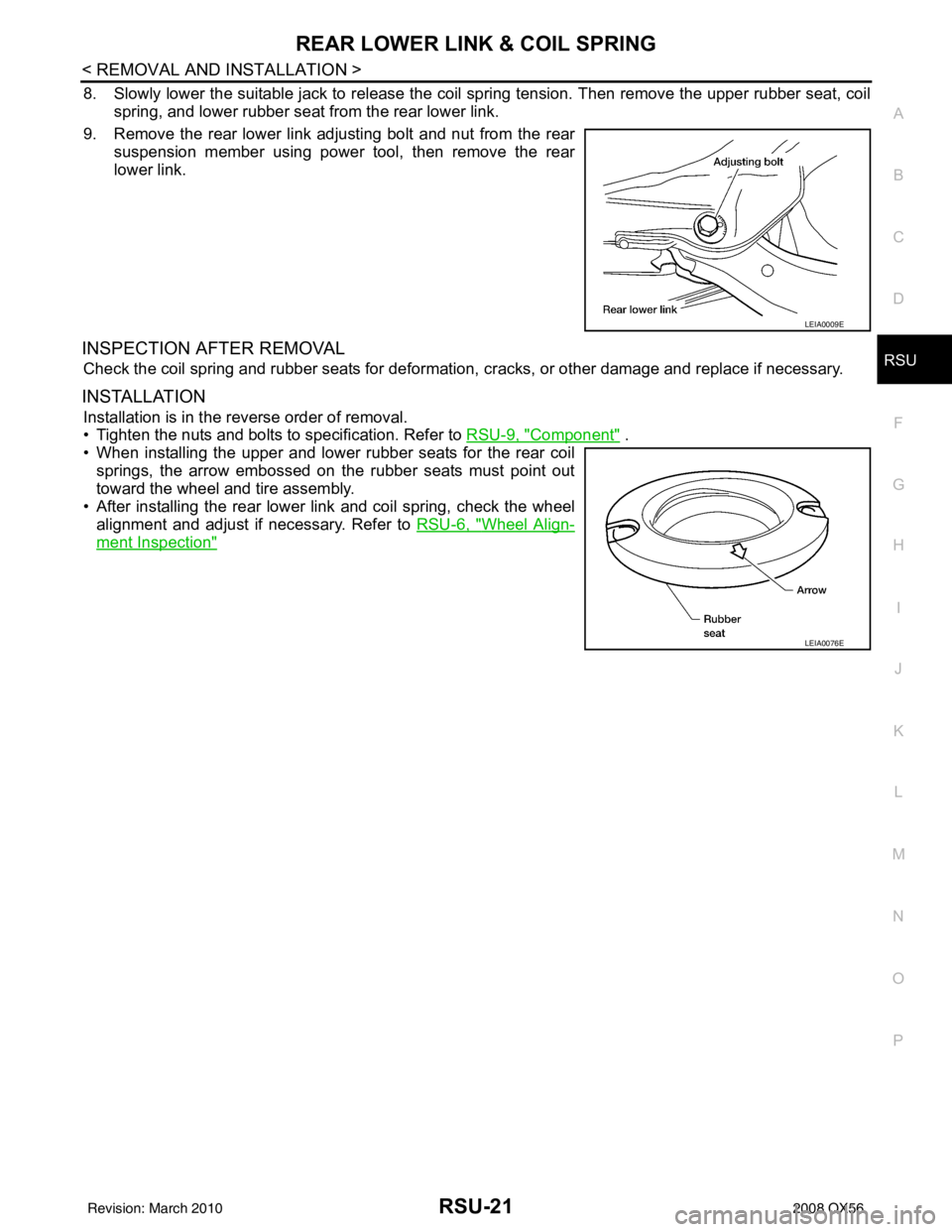
9. Remove the rear lower link adjusting bolt and nut from the rear suspension member using power tool, then remove the rear
lower link.
INSPECTION AFTER REMOVAL
Check the coil spring and rubber seats for deformation, cracks, or other damage and replace if necessary.
INSTALLATION
Installation is in the reverse order of removal.
• Tighten the nuts and bolts to specification. Refer to RSU-9, "
Component" .
• When installing the upper and lower rubber seats for the rear coil springs, the arrow embossed on the rubber seats must point out
toward the wheel and tire assembly.
• After installing the rear lower link and coil spring, check the wheel alignment and adjust if necessary. Refer to RSU-6, "
Wheel Align-
ment Inspection"
LEIA0009E
LEIA0076E
Revision: March 2010 2008 QX56
Page 3079 of 4083
SEAT BELTSSB-11
< ON-VEHICLE REPAIR >
C
DE
F
G
I
J
K L
M A
B
SB
N
O P
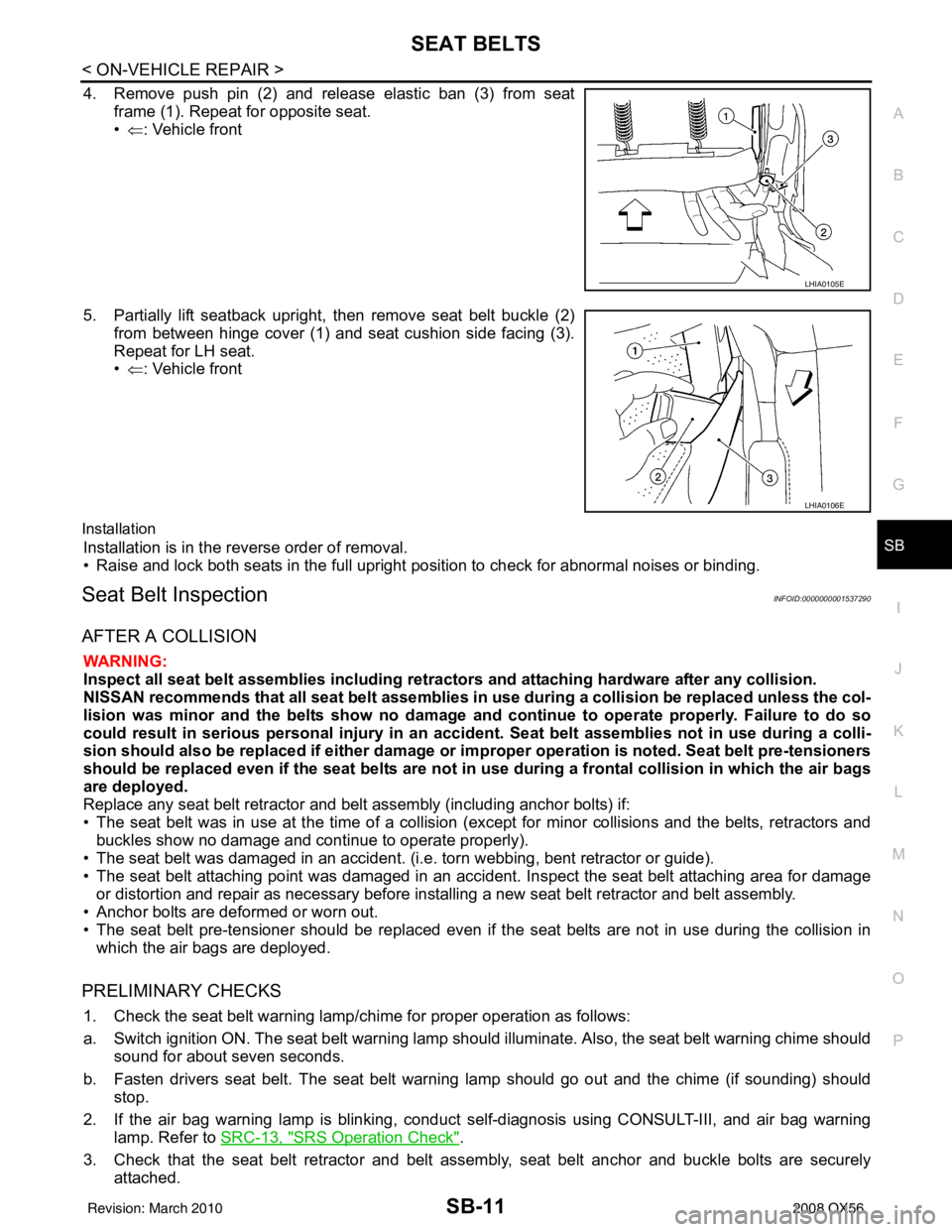
4. Remove push pin (2) and release elastic ban (3) from seat frame (1). Repeat for opposite seat.
•⇐ : Vehicle front
5. Partially lift seatback upright, then remove seat belt buckle (2) from between hinge cover (1) and seat cushion side facing (3).
Repeat for LH seat.
•⇐ : Vehicle front
Installation
Installation is in the reverse order of removal.
• Raise and lock both seats in the full upright position to check for abnormal noises or binding.
Seat Belt InspectionINFOID:0000000001537290
AFTER A COLLISION
WARNING:
Inspect all seat belt assemblies including retractors and attaching hardware after any collision.
NISSAN recommends that all seat belt assemblies in u se during a collision be replaced unless the col-
lision was minor and the belts show no damage and continue to operate properly. Failure to do so
could result in serious personal injury in an accide nt. Seat belt assemblies not in use during a colli-
sion should also be replaced if either damage or im proper operation is noted. Seat belt pre-tensioners
should be replaced even if the seat belts are not in use during a frontal collision in which the air bags
are deployed.
Replace any seat belt retractor and belt assembly (including anchor bolts) if:
• The seat belt was in use at the time of a collision (except for minor collisions and the belts, retractors and buckles show no damage and continue to operate properly).
• The seat belt was damaged in an accident. (i.e. torn webbing, bent retractor or guide).
• The seat belt attaching point was damaged in an accident. Inspect the seat belt attaching area for damage
or distortion and repair as necessary before installing a new seat belt retractor and belt assembly.
• Anchor bolts are deformed or worn out.
• The seat belt pre-tensioner should be replaced even if t he seat belts are not in use during the collision in
which the air bags are deployed.
PRELIMINARY CHECKS
1. Check the seat belt warning lamp/chime for proper operation as follows:
a. Switch ignition ON. The seat belt warning lamp should illuminate. Also, the seat belt warning chime should sound for about seven seconds.
b. Fasten drivers seat belt. The seat belt warning lamp should go out and the chime (if sounding) should stop.
2. If the air bag warning lamp is blinking, conduct self-diagnosis using CONSULT-III, and air bag warning
lamp. Refer to SRC-13, "
SRS Operation Check".
3. Check that the seat belt retractor and belt asse mbly, seat belt anchor and buckle bolts are securely
attached.
LHIA0105E
LHIA0106E
Revision: March 2010 2008 QX56
Page 3080 of 4083
SB-12
< ON-VEHICLE REPAIR >
SEAT BELTS
4. Check the shoulder seat belt guide and shoulder belt height adjuster for\
front seats. Ensure guide swivelsfreely and that belt lays flat and does not bind in guide. Ensure height adjuster operates properly and
holds securely.
5. Check retractor operation:
a. Fully extend the seat belt webbing and check for twists, tears or other damage.
b. Allow the seat belt to retract. Ensure that belt retu rns smoothly and completely into the retractor. If the
seat belt does not return smoothly, wipe the inside of the loops with a clean paper cloth, because dirt built
up in the loops of the upper anchors can c ause the seat belts to retract slowly.
c. Fasten the seat belt. Check the seat belt returns smoothly and completely to the retractor. If the belt does not return smoothly, the cause may be an accumulati on of dust or dirt. Use the “SEAT BELT TAPE SET”
and perform the following steps.
Inspect the front seat belt through-anchor:1. Pull the seat belt out to a length of 500 mm (19.69 in) or more.
2. Use a clip or other device to hold the seat belt at the center pillar belt opening.
3. Pass a thin wire through the through-anchor belt opening. Hold both ends of the wire and pull taut while moving it up and down several times along the belt opening surface to remove dirt.
4. Any dirt that cannot be removed with the wir e can be removed by cleaning the opening with a clean
cloth.
5. Apply tape at the point where the belt contacts the through-anchor belt opening.
NOTE:
Apply the tape so that there is no looseness or wrinkling.
6. Remove the clip holding the seat belt and check that the belt returns smoothly.
7. Repeat steps above as necessary to check the other seat belts.
SEAT BELT RETRACTOR ON-VEHICLE CHECK
Emergency Locking Retractors (ELR) and Automatic Locking Retractors (ALR)
NOTE:
All seat belt retractors are of the Emergency Locking Retractors (ELR) type. In an emergency (sudden stop)
the retractor will lock and prevent the belt from ext ending any further. All 3-point type seat belt retractors
except the driver's seat belt also have an Automati c Locking Retractors (ALR) mode. The ALR mode (also
called child restraint mode) is used when installing child seats. The ALR mode is activated when the seat belt
is fully extended. When the belt is then retracted partiall y, the ALR mode automatically locks the seat belt in a
specific position so the belt cannot be extended any furt her. To cancel the ALR mode, allow the seat belt to
fully wind back into the retractor.
Check the seat belt retractors using the following test(s ) to determine if a seat belt retractor and belt assembly
is operating properly.
ELR Function Stationary Check
Grasp the shoulder belt and pull forward quickly. The re tractor should lock and prevent the belt from extending
further.
ALR Function Stationary Check
1. Pull out entire length of seat belt from retractor until a click is heard.
2. Retract the belt partially. A clicking noise should be hear d as the belt retracts indicating that the retractor is
in the Automatic Locking Retractor (ALR) mode.
3. Grasp the seat belt and try to pull out the retractor. The belt must lock and not extend any further. If neces-
sary replace the seat belt retractor and belt assembly.
4. Allow the entire length of the belt to re tract to cancel the automatic locking mode.
ELR Function Moving Check
WARNING:
Perform the following test in a safe, open area clear of other vehicles and obstructions (for example, a
large, empty parking lot). Road surface must be p aved and dry. DO NOT perform the following test on
wet or gravel roads or on public streets and highw ays. This could result in an accident and serious
personal injury. The driver and passenger must be prepared to brace themselves in the event the
retractor does not lock.
1. Fasten drivers seat belt. Buckle a passenger in to the seat for the belt that is to be tested.
Revision: March 2010 2008 QX56
Page 3123 of 4083
SE-1
BODY INTERIOR
C
DE
F
G H
I
K L
M
SECTION SE
A
B
SE
N
O P
CONTENTS
SEAT
BASIC INSPECTION ....... .............................3
DIAGNOSIS AND REPAIR WORKFLOW ..... .....3
Work Flow ........................................................... ......3
INSPECTION AND ADJUSTMENT .....................5
Preliminary Check ............................................... ......5
FUNCTION DIAGNOSIS ...............................6
THIRD ROW POWER FOLDING SEAT ......... .....6
System Description ............................................. ......6
Component Parts Location ........................................7
Component Description .............................................7
COMPONENT DIAGNOSIS ..........................8
POWER SEAT .....................................................8
Wiring Diagram — Passenger Side — ................ ......8
HEATED SEAT ...................................................12
Description ..............................................................12
Wiring Diagram .......................................................13
THIRD SEAT ......................................................18
Power Supply and Ground Circuit Check for Third
Row Power Folding Seat Control Unit ................. ....
18
Third Row Power Folding Seat Switch ....................19
Third Row Power Folding Seat Motor .....................19
ECU DIAGNOSIS .........................................21
THIRD ROW POWER FOLDING SEAT CON-
TROL UNIT .........................................................
21
Reference Value ................................................. ....21
Wiring Diagram .......................................................23
DTC Index ...............................................................28
Fail Safe ..................................................................29
SYMPTOM DIAGNOSIS ..............................30
THIRD ROW POWER FOLDING SEAT ......... ....30
Symptom Table ................................................... ....30
NONE OF THE THIRD ROW POWER FOLD-
ING SEATS WILL OPERATE WITH ANY
SWITCH. ............................................................
31
None of the Third Row Power Folding Seats Will
Operate With Any Third Row Power Folding Seat
Switch .................................................................. ....
31
ONLY ONE THIRD ROW POWER FOLDING
SEAT WILL OPERATE. ....................................
32
Only One Third Row Power Folding Seat Will Op-
erate .................................................................... ....
32
THIRD ROW POWER FOLDING SEAT WILL
OPERATE IN ONLY ONE DIRECTION. ...........
34
Third Row Power Folding Seat Will Operate in
Only One Direction .............................................. ....
34
THIRD ROW POWER FOLDING SEAT WILL
STOP SHORT OF IT’S FULLY UP OR DOWN
POSITION. .........................................................
35
Third Row Power Folding Seat Stops Short of its
Fully Up or Down Position .......................................
35
THIRD ROW POWER FOLDING SEAT
MAKES EXCESSIVE NOISE WHILE MOV-
ING. ...................................................................
36
Third Row Power Folding Seat Makes Excessive
Noise While Moving ............................................. ....
36
SQUEAK AND RATTLE TROUBLE DIAG-
NOSES ..............................................................
37
Work Flow ................................................................37
Generic Squeak and Rattle Troubleshooting ...........39
Diagnostic Worksheet ..............................................41
PRECAUTION ..............................................43
PRECAUTIONS .................................................43
Precaution for Supplemental Restraint System
(SRS) "AIR BAG" and "SEAT BELT PRE-TEN-
SIONER" ............................................................. ....
43
Revision: March 2010 2008 QX56
Page 3127 of 4083
INSPECTION AND ADJUSTMENTSE-5
< BASIC INSPECTION >
C
DE
F
G H
I
K L
M A
B
SE
N
O P
INSPECTION AND ADJUSTMENT
Preliminary CheckINFOID:0000000001735710
1.FOREIGN OBJECTS
Check the following:
• objects on or behind the seats that could cause binding
• objects under the seats that may be in terfering with the seat’s moving parts
Are there any foreign objects that could be causing interference with the seats?
YES >> Remove objects.
NO >> GO TO 2.
2.WIRING CONNECTIONS
1. Disconnect third row power folding seat c ontrol unit and seat motor harness connectors.
2. Check terminals for damage or loose connections.
3. Reconnect harness connectors.
Are any connectors damaged or loose?
YES >> Repair or replace damaged parts.
NO >> GO TO 3.
3.POWER AND GROUND
Check power supply and ground circuits for third row power folding seat control unit. Refer to SE-18, "
Power
Supply and Ground Circuit Check for Third Row Power Folding Seat Control Unit".
Is the inspection result normal?
YES >> Refer to SE-28, "DTC Index".
NO >> Repair or replace as necessary.
Revision: March 2010 2008 QX56
Page 3129 of 4083
THIRD ROW POWER FOLDING SEATSE-7
< FUNCTION DIAGNOSIS >
C
DE
F
G H
I
K L
M A
B
SE
N
O P
Component Parts LocationINFOID:0000000001735712
Component DescriptionINFOID:0000000001735713
ALJIA0088ZZ
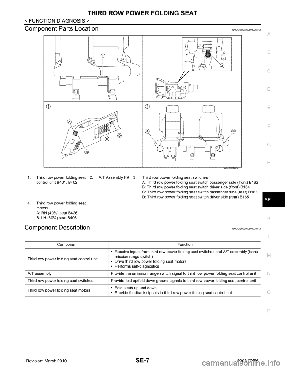
1. Third row power folding seat control unit B401, B402 2. A/T Assembly F9 3. Third row power folding seat switches
A: Third row power folding seat sw itch passenger side (front) B162
B: Third row power folding seat switch driver side (front) B164
C: Third row power folding seat switch passenger side (rear) B163
D: Third row power folding seat switch driver side (rear) B165
4. Third row power folding seat motors
A: RH (40%) seat B426
B: LH (60%) seat B403
Component Function
Third row power folding seat control unit • Receive inputs from third row power folding seat switches and A/T assembly (trans-
mission range switch)
• Drive third row powe r folding seat motors
• Performs self-diagnostics
A/T assembly Provide transmission range switch signal to third row power folding seat control unit
Third row power folding seat switches Provide fold up/fold down ground signals to third row power folding seat control unit
Third row power folding seat motors • Fold seats up and down
• Provide feedback signals to third row power folding seat control unit
Revision: March 2010
2008 QX56