Page 3515 of 4083

ST-24
< REMOVAL AND INSTALLATION >
POWER STEERING GEAR AND LINKAGE
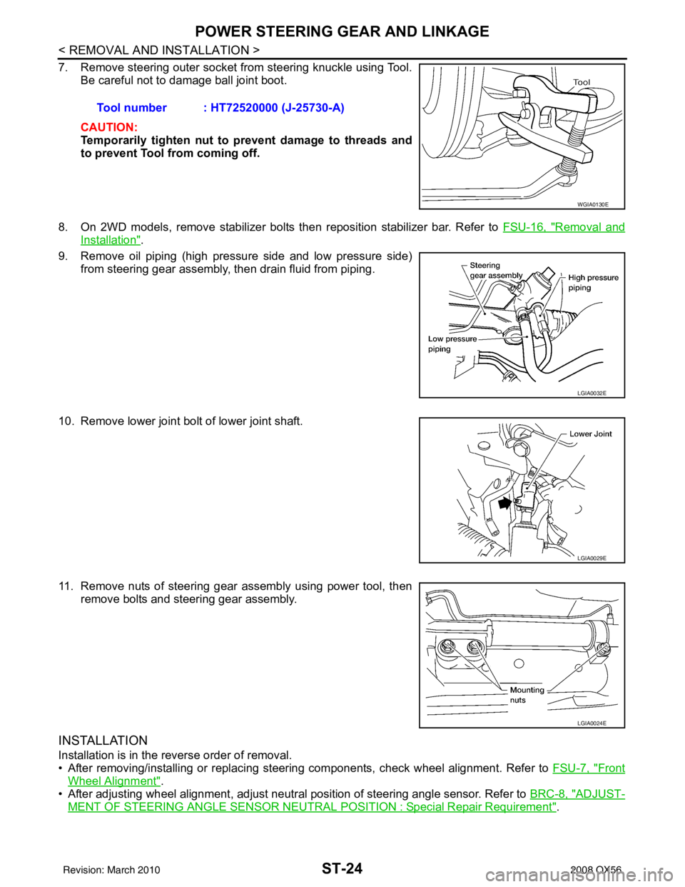
7. Remove steering outer socket from steering knuckle using Tool.Be careful not to damage ball joint boot.
CAUTION:
Temporarily tighten nut to prevent damage to threads and
to prevent Tool from coming off.
8. On 2WD models, remove stabilizer bolts then reposition stabilizer bar. Refer to FSU-16, "
Removal and
Installation".
9. Remove oil piping (high pressure side and low pressure side) from steering gear assembly, then drain fluid from piping.
10. Remove lower joint bolt of lower joint shaft.
11. Remove nuts of steering gear assembly using power tool, then remove bolts and steering gear assembly.
INSTALLATION
Installation is in the reverse order of removal.
• After removing/installing or replacing steering components, check wheel alignment. Refer to FSU-7, "
Front
Wheel Alignment".
• After adjusting wheel alignment, adjust neutral position of steering angle sensor. Refer to BRC-8, "
ADJUST-
MENT OF STEERING ANGLE SENSOR NEUTRAL POSITION : Special Repair Requirement".
Tool number : HT72520000 (J-25730-A)
WGIA0130E
LGIA0032E
LGIA0029E
LGIA0024E
Revision: March 2010
2008 QX56
Page 3517 of 4083
ST-26
< REMOVAL AND INSTALLATION >
POWER STEERING OIL PUMP
POWER STEERING OIL PUMP
Removal and InstallationINFOID:0000000004920102
REMOVAL
1. Drain power steering fluid from reservoir tank.
2. Remove engine room cover. Refer to EM-24, "
Removal and Installation".
3. Remove air duct assembly. Refer to EM-25, "
Removal and Installation".
4. Remove power steering reservoir tank.
5. Remove serpentine drive belt belt from auto tensioner and power steering pump. Refer to EM-13,
"Removal and Installation".
6. Disconnect pressure sensor electrical connector.
7. Remove high pressure and low pressure piping from power steering oil pump. Refer to ST-27
.
8. Remove bolts, then remove power steering pump.
INSTALLATION
Installation is in the reverse order of removal. Refer to ST-27 for tightening torque.
• After installation, bleed air. Refer to ST-13, "
Air Bleeding Hydraulic System".
NOTE:
Belt tension is automatic and requires no adjustment.
Revision: March 2010 2008 QX56
Page 3529 of 4083
ST-38
< SERVICE DATA AND SPECIFICATIONS (SDS)
SERVICE DATA AND SPECIFICATIONS (SDS)
Oil Pump
INFOID:0000000001534689
Steering FluidINFOID:0000000001534690
Rack sliding force At the neutral point:
Range within
± 11.5 mm
(± 0.453 in) from the neutral
position
(in power ON) Area average value 147
− 211 N (14.99 − 21.52 kg, 33.1 − 47.52 lb)
Allowable variation 98 N (10 kg, 22 lb) or less
Whole area (in power OFF) Peak value
294 N (30.0 kg, 66 lb) or less
Allowable variation 147 N (16 kg, 35 lb) or less
Steering gear model
PR26AM
Relief oil pressure
9.0 − 9.8 mPa (91.77 − 99.93 kg/cm2, 1305.34 − 1421.37 psi)
Fluid capacity
Approx. 1.0 (1-1/8 US qt, 7/8 Imp qt)
Revision: March 2010 2008 QX56
Page 4007 of 4083
WW-10
< FUNCTION DIAGNOSIS >
REAR WIPER AND WASHER SYSTEM
Component Parts Location
INFOID:0000000001735571
Component DescriptionINFOID:0000000001735572
1. Steering column (v iew with instrument
panel removed) 2. BCM M18, M19, M20
3. Rear washer nozzle
4. Rear wiper motor D704 5. Air cleaner case6. Front and rear washer motor connector
E105
7. Washer fluid reservoir 8. Combination switch M28 9. Glass hatch ajar switch D707
ALLIA0842ZZ
Part Description
BCM • Judges each switch status by the combination switch reading function.
• Supplies power to the rear wiper motor.
• Performs the auto stop control of the rear wiper.
Combination switch
(Wiper and washer switch) Refer to BCS-7, "
System Diagram".
Revision: March 2010
2008 QX56
Page:
< prev 1-8 9-16 17-24