2008 INFINITI QX56 height adjustment
[x] Cancel search: height adjustmentPage 2040 of 4083

EXL-112
< ON-VEHICLE REPAIR >
ADJUSTMENT AND INSPECTION
• See that vehicle is unloaded (except for full levels of coolant,engine oil and fuel, and spare tire, jack, and tools). Have the driver
or equivalent weight placed in driver seat.
Adjust aiming in the vertical direction by turning the adjustment
screw.
NOTE:
Access adjustment screw from underneath front bumper. Turn screw
clockwise to raise pattern and counterclockwise to lower pattern.
1. Set the distance between the screen and the center of the fog lamp lens as shown.
2. Turn front fog lamps ON.
3. Adjust front fog lamps using adjusting screw so that the top edge of the high intensity zone is 200 mm (7.9 in) below the height of
the fog lamp centers as shown.
• When performing adjustment, if necessary, cover the head-lamps and opposite fog lamp.
SEL350X
MEL327G
MEL328GA
Revision: March 2010 2008 QX56
Page 2124 of 4083

ON-VEHICLE SERVICEFSU-7
< ON-VEHICLE MAINTENANCE >
C
DF
G H
I
J
K L
M A
B
FSU
N
O P
ON-VEHICLE MAINTENANCE
ON-VEHICLE SERVICE
Front Suspension PartsINFOID:0000000001534627
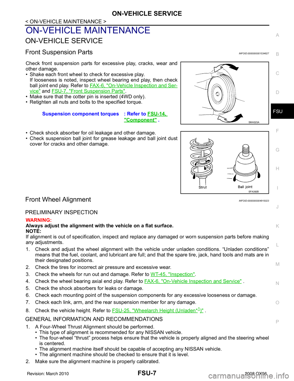
Check front suspension parts for excessive play, cracks, wear and
other damage.
• Shake each front wheel to check for excessive play. If looseness is noted, inspect wheel bearing end play, then check
ball joint end play. Refer to FA X - 6 , "
On-Vehicle Inspection and Ser-
vice" and FSU-7, "Front Suspension Parts".
• Make sure that the cotter pin is inserted (4WD only).
• Retighten all nuts and bolts to the specified torque.
• Check shock absorber for oil leakage and other damage.
• Check suspension ball joint for grease leakage and ball joint dust cover for cracks and other damage.
Front Wheel AlignmentINFOID:0000000004915023
PRELIMINARY INSPECTION
WARNING:
Always adjust the alignment with the vehicle on a flat surface.
NOTE:
If alignment is out of specificat ion, inspect and replace any damaged or worn suspension parts before making
any adjustments.
1. Check and adjust the wheel alignment with the vehicle under unladen conditions. “Unladen conditions”
means that the fuel, coolant, and lubricant are full; and that the spare tire, jack, hand tools and mats are in
their designated positions.
2. Check the tires for incorrect air pressure and excessive wear.
3. Check the wheels for run out and damage. Refer to WT-45, "
Inspection".
4. Check the wheel bearing axial end play. Refer to FAX-6, "
On-Vehicle Inspection and Service" .
5. Check the shock absorbers for leaks or damage.
6. Check each mounting point of the suspension components for any excessive looseness or damage.
7. Check each link, arm, and the rear suspension member for any damage.
8. Check the vehicle height. Refer to FSU-25, "
Wheelarch Height (Unladen*1)" .
GENERAL INFORMATION AND RECOMMENDATIONS
1. A Four-Wheel Thrust Alignment should be performed.
• This type of alignment is re commended for any NISSAN vehicle.
• The four-wheel “thrust” process helps ensure that the vehicle is properly aligned and the steering wheel
is centered.
• The alignment machine itself should be ca pable of accepting any NISSAN vehicle.
• The alignment machine should be checked to ensure that it is level.
2. Make sure the alignment machine is properly calibrated. Suspension component torques : Refer to
FSU-14,
"Component" . SMA525A
SFA392B
Revision: March 2010 2008 QX56
Page 3035 of 4083

SUNROOF SYSTEMRF-51
< ON-VEHICLE REPAIR >
C
DE
F
G H
I
J
L
M A
B
RF
N
O P
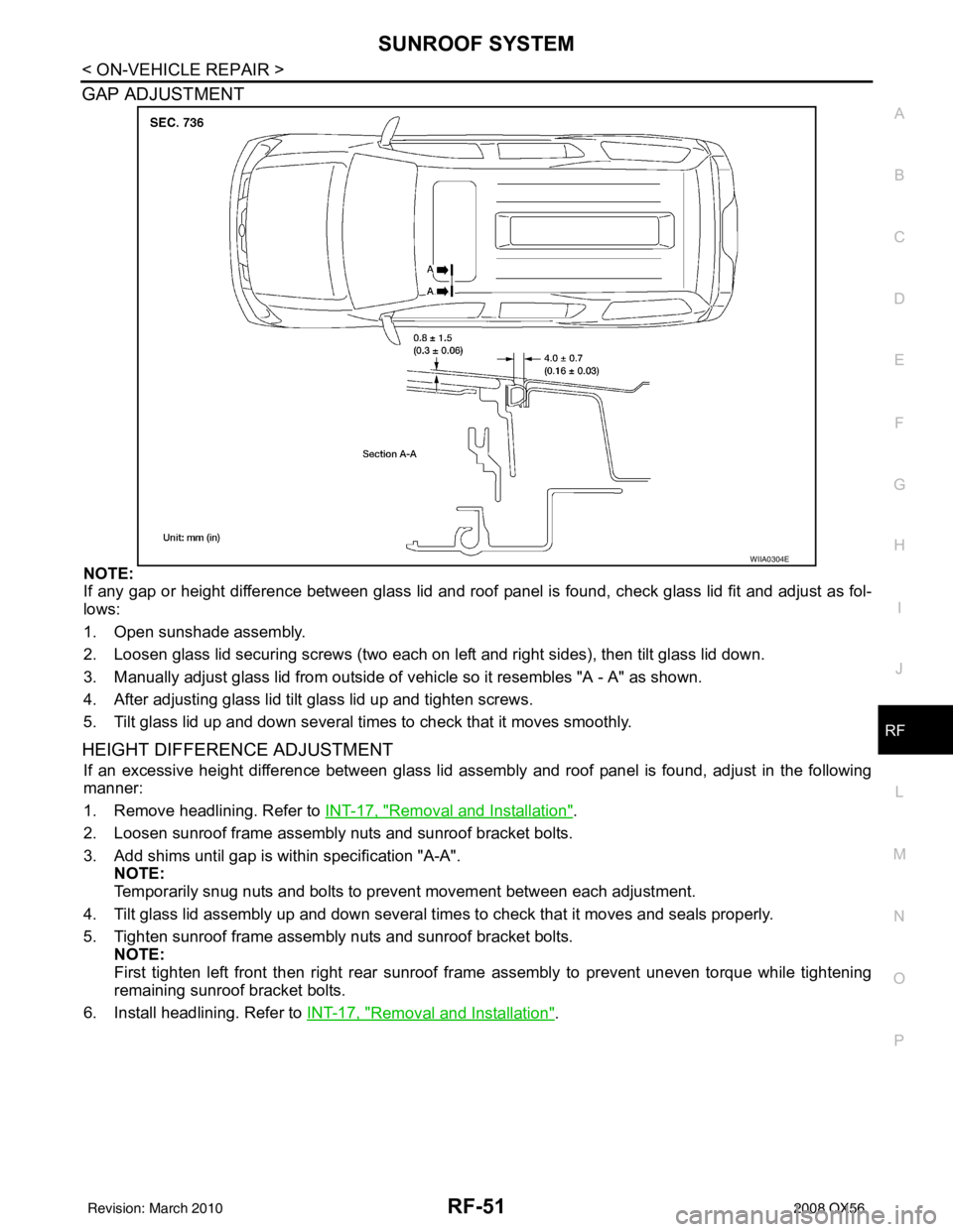
GAP ADJUSTMENT
NOTE:
If any gap or height difference between glass lid and roof panel is found, check glass lid fit and adjust as fol-
lows:
1. Open sunshade assembly.
2. Loosen glass lid securing screws (two each on left and right sides), then tilt glass lid down.
3. Manually adjust glass lid from outside of v ehicle so it resembles "A - A" as shown.
4. After adjusting glass lid tilt glass lid up and tighten screws.
5. Tilt glass lid up and down several times to check that it moves smoothly.
HEIGHT DIFFERE NCE ADJUSTMENT
If an excessive height difference between glass lid assemb ly and roof panel is found, adjust in the following
manner:
1. Remove headlining. Refer to INT-17, "
Removal and Installation".
2. Loosen sunroof frame assembly nuts and sunroof bracket bolts.
3. Add shims until gap is within specification "A-A". NOTE:
Temporarily snug nuts and bolts to prevent movement between each adjustment.
4. Tilt glass lid assembly up and down several times to check that it moves and seals properly.
5. Tighten sunroof frame assembly nuts and sunroof bracket bolts. NOTE:
First tighten left front then right rear sunroof frame assembly to prevent uneven torque while tightening
remaining sunroof bracket bolts.
6. Install headlining. Refer to INT-17, "
Removal and Installation".
WIIA0304E
Revision: March 2010 2008 QX56
Page 3045 of 4083

RSU-6
< ON-VEHICLE MAINTENANCE >
REAR SUSPENSION ASSEMBLY
ON-VEHICLE MAINTENANCE
REAR SUSPENSION ASSEMBLY
On-Vehicle Inspection and ServiceINFOID:0000000001534667
Check all of the component mountings for any excessive looseness, or back lash. Check the components for
any excessive wear, damage, or abnormal conditions. Repair or replace the components as necessary.
SHOCK ABSORBER INSPECTION
• Check the shock absorbers for any air leaks or damage, and replace as necessary.
• Check the hoses for any air leaks or damage, and replace as necessary.
Wheel Alignment InspectionINFOID:0000000001534668
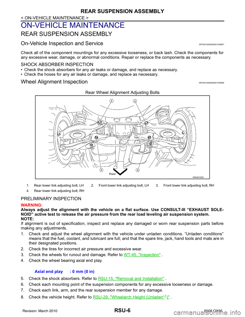
Rear Wheel Alignment Adjusting Bolts
PRELIMINARY INSPECTION
WARNING:
Always adjust the alignment with the vehicle on a flat surface. Use CONSULT-III “EXHAUST SOLE-
NOID” active test to release the air pressure from the rear load leveling air suspension system.
NOTE:
If alignment is out of specificat ion, inspect and replace any damaged or worn rear suspension parts before
making any adjustments.
1. Check and adjust the wheel alignment with the vehicle under unladen conditions. “Unladen conditions”
means that the fuel, coolant, and lubricant are full; and that the spare tire, jack, hand tools and mats are in
their designated positions.
2. Check the tires for incorrect air pressure and excessive wear.
3. Check the wheels for runout and damage. Refer to WT-45, "
Inspection" .
4. Check the wheel bearing axial end play.
5. Check the shock absorbers. Refer to RSU-15, "
Removal and Installation" .
6. Check each mounting point of the suspension components for any excessive looseness or damage.
7. Check each link, arm, and the rear suspension member for any damage.
8. Check the vehicle height. Refer to RSU-29, "
Wheelarch Height (Unladen*1)" .
WEIA0102E
1. Rear lower link adjusting bolt, LH 2. Front lower link adjusting bolt, LH 3. Front lower link adjusting bolt, RH
4. Rear lower link adjusting bolt, RH
Axial end play : 0 mm (0 in)
Revision: March 2010 2008 QX56
Page 3090 of 4083

DIAGNOSIS SYSTEM (SUSPENSION CONTROL UNIT)
SCS-7
< FUNCTION DIAGNOSIS >
C
D F
G H
I
J
K L
M A
B
SCS
N
O P
DIAGNOSIS SYSTEM (SUS PENSION CONTROL UNIT)
CONSULT-III FunctionINFOID:0000000001731959
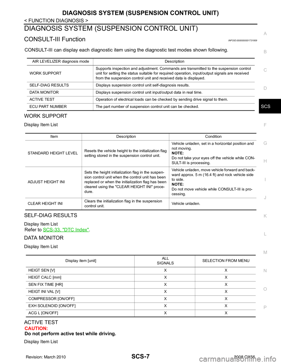
CONSULT-III can display each diagnostic item using the diagnostic test modes shown following.
WORK SUPPORT
Display Item List
SELF-DIAG RESULTS
Display Item List
Refer to SCS-33, "DTC Index".
DATA MONITOR
Display Item List
ACTIVE TEST
CAUTION:
Do not perform active test while driving.
Display Item List
AIR LEVELIZER diagno sis mode Description
WORK SUPPORT Supports inspection and adjustment. Commands are transmitted to the suspension control
unit for setting the status suitable for required operation, input/output signals are received
from the suspension control unit and received data is displayed.
SELF-DIAG RESULTS Displays suspension control unit self-diagnosis results.
DATA MONITOR Displays suspension control unit input/output data in real time.
ACTIVE TEST Operation of electrical loads can be checked by sending drive signal to them.
ECU PART NUMBER The part number of suspension control unit can be checked.
ItemDescription Condition
STANDARD HEIGHT LEVEL Resets the vehicle height to the initialization flag
setting stored in the suspension control unit. Vehicle unladen, set in a horizontal position and
not moving.
NOTE:
Do not take your eyes off the vehicle while CON-
SULT-III is processing.
ADJUST HEIGHT INI Sets the height initialization flag in the suspen-
sion control unit when the control unit has been
replaced or when the initialization flag has been
cleared using the "CLEAR HEIGHT INI" proce-
dure. Vehicle unladen, move vehicle forward and back-
ward approx. 5 m (16.4 ft) and rock vehicle side
to side.
NOTE:
Do not move vehicle wh
ile CONSULT-III is pro-
cessing.
CLEAR HEIGHT INI Clears the initialization flag in the suspension
control unit. Vehicle unladen.
Display item [unit]
ALL
SIGNALS SELECTION FROM MENU
HEIGT SEN [V] XX
HEIGT CALC [mm] XX
SEN FIX TIME [HR] XX
HEIGT INI VAL [V] XX
COMPRESSOR [ON/OFF] XX
EXH SOLENOID [ON/OFF] XX
ACG L [ON/OFF] XX
Revision: March 2010 2008 QX56