2008 INFINITI QX56 ad blue
[x] Cancel search: ad bluePage 1230 of 4083
![INFINITI QX56 2008 Factory Service Manual DLN-200
< SERVICE DATA AND SPECIFICATIONS (SDS) [PROPELLER SHAFT: 2S1410]
SERVICE DATA AND SPECIFICATIONS (SDS)
Unit: N·m (kg-m, in-lb)
Journal Axial Play
Unit: mm (in)
Snap RingINFOID:00000000016044 INFINITI QX56 2008 Factory Service Manual DLN-200
< SERVICE DATA AND SPECIFICATIONS (SDS) [PROPELLER SHAFT: 2S1410]
SERVICE DATA AND SPECIFICATIONS (SDS)
Unit: N·m (kg-m, in-lb)
Journal Axial Play
Unit: mm (in)
Snap RingINFOID:00000000016044](/manual-img/42/57030/w960_57030-1229.png)
DLN-200
< SERVICE DATA AND SPECIFICATIONS (SDS) [PROPELLER SHAFT: 2S1410]
SERVICE DATA AND SPECIFICATIONS (SDS)
Unit: N·m (kg-m, in-lb)
Journal Axial Play
Unit: mm (in)
Snap RingINFOID:0000000001604438
Unit: mm (in)
*Always check with the Parts Department for the latest parts information.Item
Limit
Propeller shaft joint flex effort 2.26 (0.23, 20) or less
ItemLimit
Journal axial play 0.02 (0.0008) or less
ThicknessColorPart Number*
1.99 (0.0783) White37146-C9400
2.02 (0.0795) Yellow37147-C9400
2.05 (0.0807) Red37148-C9400
2.08 (0.0819) Green37149-C9400
2.11 (0.0831) Blue37150-C9400
2.14 (0.0843) Light brown 37151-C9400
2.17 (0.0854) Black37152-C9400
2.20 (0.0866) No paint37153-C9400
Revision: March 2010 2008 QX56
Page 1843 of 4083
EM-40
< ON-VEHICLE REPAIR >
FUEL INJECTOR AND FUEL TUBE
FUEL INJECTOR AND FUEL TUBE
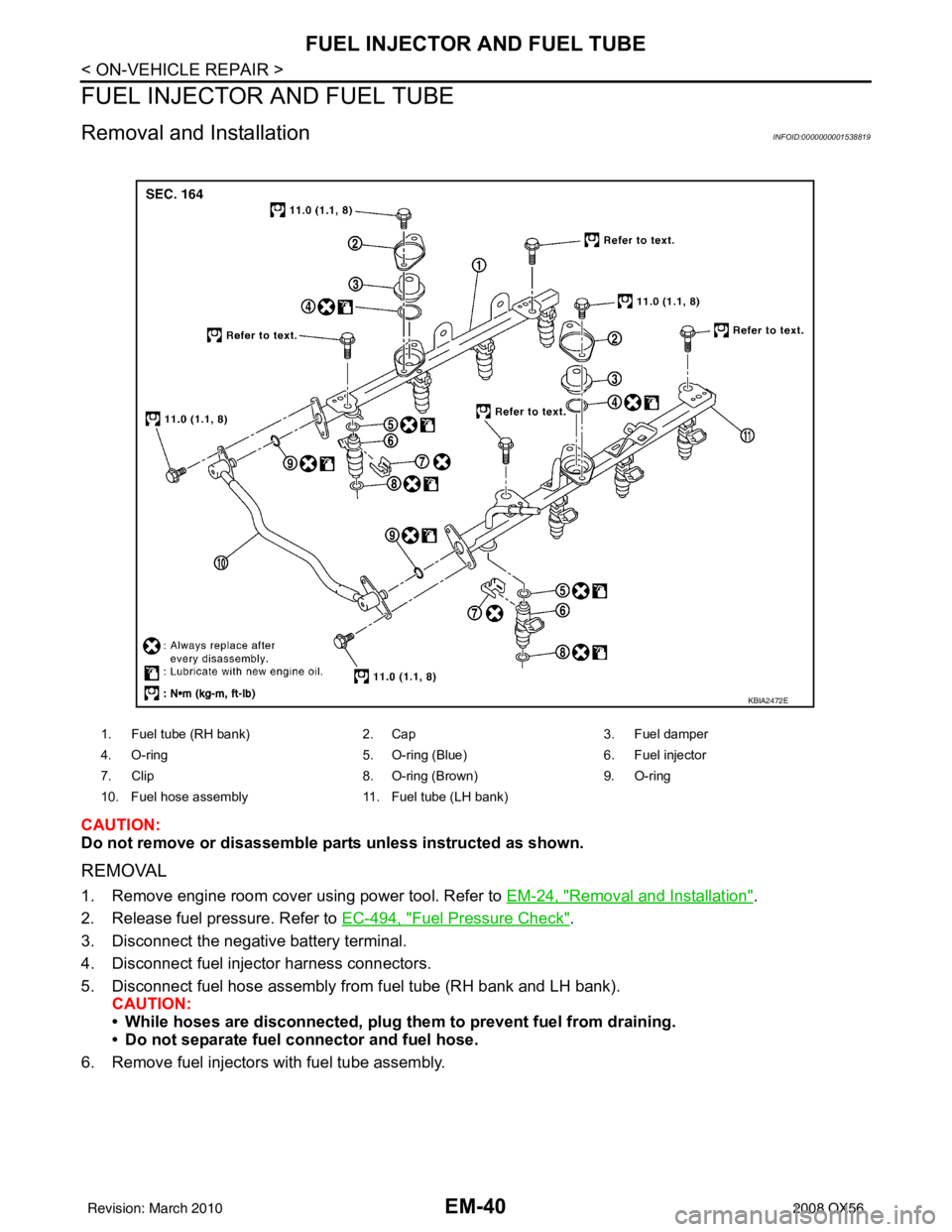
Removal and InstallationINFOID:0000000001538819
CAUTION:
Do not remove or disassemble parts unless instructed as shown.
REMOVAL
1. Remove engine room cover using power tool. Refer to EM-24, "Removal and Installation".
2. Release fuel pressure. Refer to EC-494, "
Fuel Pressure Check".
3. Disconnect the negative battery terminal.
4. Disconnect fuel injector harness connectors.
5. Disconnect fuel hose assembly from fuel tube (RH bank and LH bank). CAUTION:
• While hoses are disconnected, plug th em to prevent fuel from draining.
• Do not separate fuel co nnector and fuel hose.
6. Remove fuel injectors with fuel tube assembly.
1. Fuel tube (RH bank) 2. Cap3. Fuel damper
4. O-ring 5. O-ring (Blue)6. Fuel injector
7. Clip 8. O-ring (Brown)9. O-ring
10. Fuel hose assembly 11. Fuel tube (LH bank)
KBIA2472E
Revision: March 2010 2008 QX56
Page 1844 of 4083
FUEL INJECTOR AND FUEL TUBEEM-41
< ON-VEHICLE REPAIR >
C
DE
F
G H
I
J
K L
M A
EM
NP
O
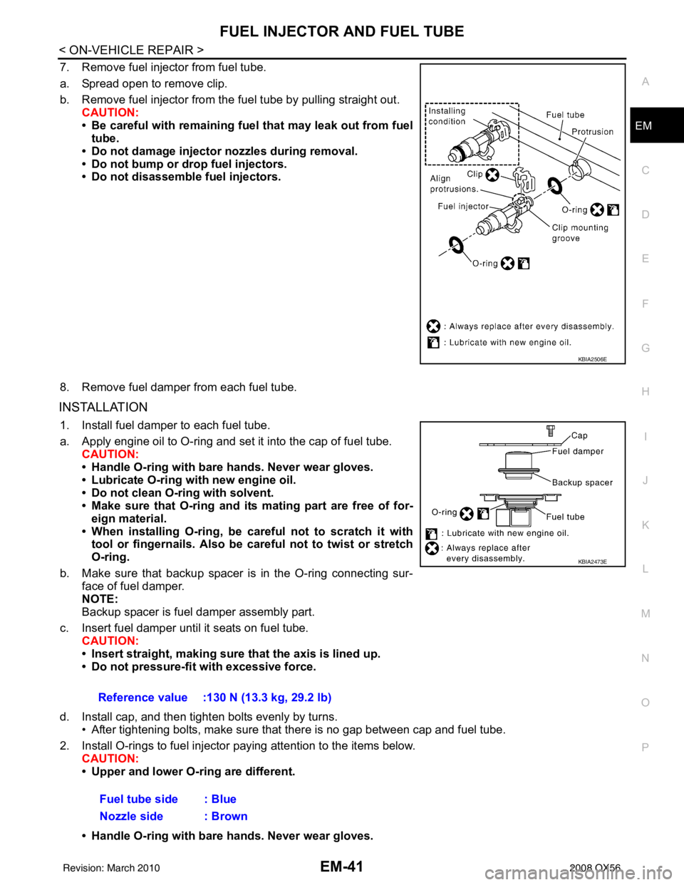
7. Remove fuel injector from fuel tube.
a. Spread open to remove clip.
b. Remove fuel injector from the
fuel tube by pulling straight out.
CAUTION:
• Be careful with remaining fuel that may leak out from fuel
tube.
• Do not damage injector nozzles during removal.
• Do not bump or drop fuel injectors.
• Do not disassemble fuel injectors.
8. Remove fuel damper from each fuel tube.
INSTALLATION
1. Install fuel damper to each fuel tube.
a. Apply engine oil to O-ring and set it into the cap of fuel tube. CAUTION:
• Handle O-ring with bare hands. Never wear gloves.
• Lubricate O-ring with new engine oil.
• Do not clean O-ring with solvent.
• Make sure that O-ring and its mating part are free of for- eign material.
• When installing O-ring, be car eful not to scratch it with
tool or fingernails. Also be careful not to twist or stretch
O-ring.
b. Make sure that backup spacer is in the O-ring connecting sur- face of fuel damper.
NOTE:
Backup spacer is fuel damper assembly part.
c. Insert fuel damper until it seats on fuel tube. CAUTION:
• Insert straight, making sure that the axis is lined up.
• Do not pressure-fit with excessive force.
d. Install cap, and then tighten bolts evenly by turns. • After tightening bolts, make sure that there is no gap between cap and fuel tube.
2. Install O-rings to fuel injector paying attention to the items below. CAUTION:
• Upper and lower O-ring are different.
• Handle O-ring with bare hands. Never wear gloves.
KBIA2506E
Reference value :130 N (13.3 kg, 29.2 lb)
Fuel tube side : Blue
Nozzle side : Brown
KBIA2473E
Revision: March 2010 2008 QX56
Page 1851 of 4083
EM-48
< ON-VEHICLE REPAIR >
TIMING CHAIN
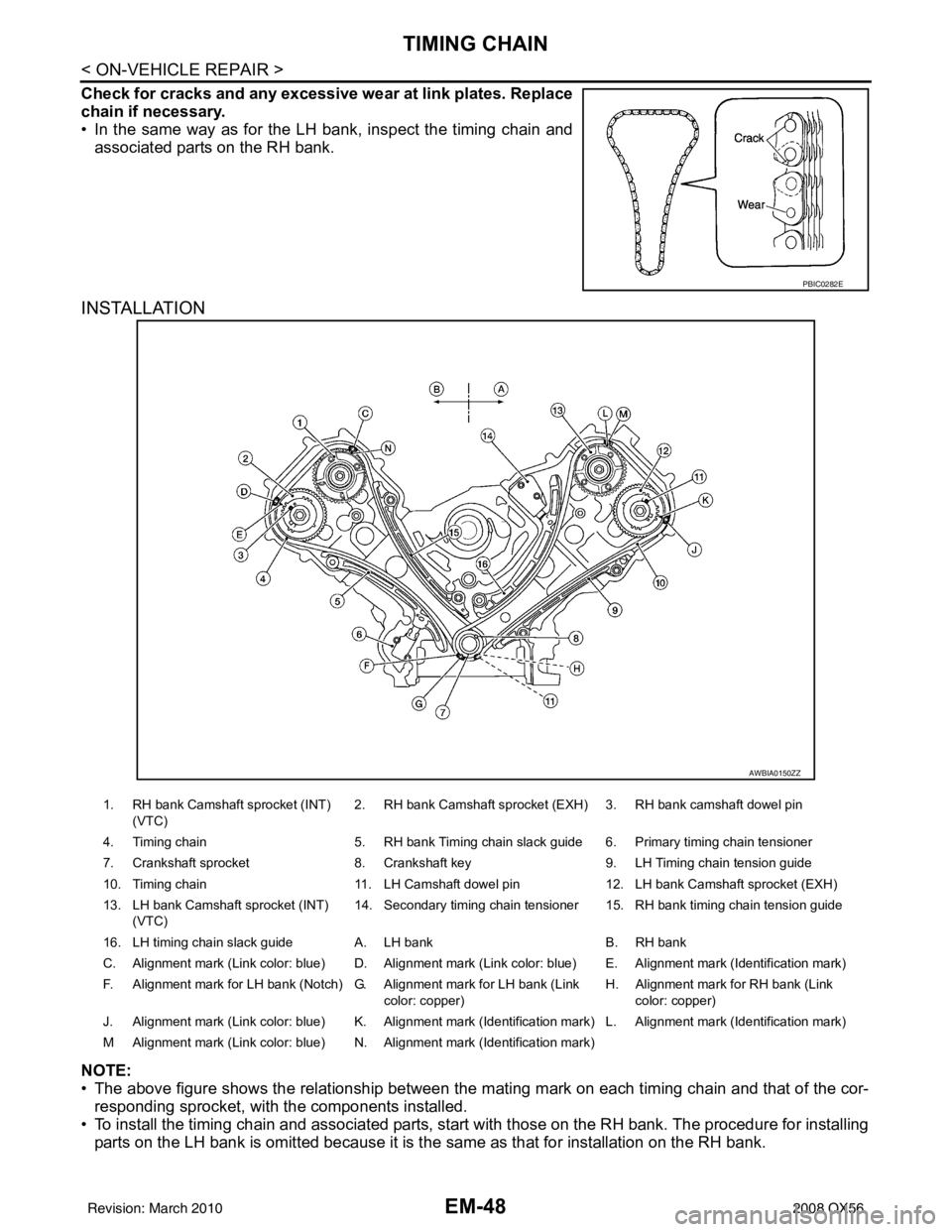
Check for cracks and any excessive wear at link plates. Replace
chain if necessary.
• In the same way as for the LH bank, inspect the timing chain andassociated parts on the RH bank.
INSTALLATION
NOTE:
• The above figure shows the relationship between the ma ting mark on each timing chain and that of the cor-
responding sprocket, with the components installed.
• To install the timing chain and associated parts, start with those on the RH bank. The procedure for installing parts on the LH bank is omitted because it is t he same as that for installation on the RH bank.
PBIC0282E
AWBIA0150ZZ
1. RH bank Camshaft sprocket (INT)
(VTC) 2. RH bank Camshaft sprocket (EXH) 3. RH bank camshaft dowel pin
4. Timing chain 5. RH bank Timing chain slack guide 6. Primary timing chain tensioner
7. Crankshaft sprocket 8. Crankshaft key 9. LH Timing chain tension guide
10. Timing chain 11. LH Camshaft dowel pin 12. LH bank Camshaft sprocket (EXH)
13. LH bank Camshaft sprocket (INT) (VTC) 14. Secondary timing chain tensioner 15. RH bank timing chain tension guide
16. LH timing chain slack guide A. LH bank B. RH bank
C. Alignment mark (Link color: blue) D. Alignment mark (Link color: blue) E. Alignment mark (Identification mark)
F. Alignment mark for LH bank (Notch) G. Alignment mark for LH bank (Link color: copper)H. Alignment mark
for RH bank (Link
color: copper)
J. Alignment mark (Link color: blue) K. Alignment mark (Identification mark) L. Alignment mark (Identification mark)
M Alignment mark (Link color: blue) N. Alignment mark (Identification mark)
Revision: March 2010 2008 QX56
Page 1878 of 4083
CYLINDER HEADEM-75
< ON-VEHICLE REPAIR >
C
DE
F
G H
I
J
K L
M A
EM
NP
O
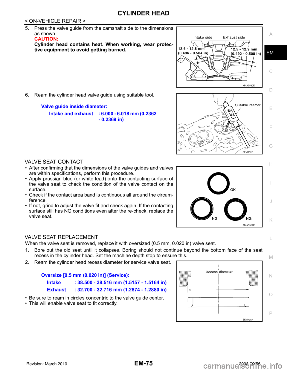
5. Press the valve guide from the camshaft side to the dimensions
as shown.
CAUTION:
Cylinder head contains heat . When working, wear protec-
tive equipment to avo id getting burned.
6. Ream the cylinder head valve guide using suitable tool.
VALVE SEAT CONTACT
• After confirming that the dimensions of the valve guides and valves are within specifications, perform this procedure.
• Apply prussian blue (or white lead) onto the contacting surface of the valve seat to check the condition of the valve contact on the
surface.
• Check if the contact area band is continuous all around the circum- ference.
• If not, grind to adjust the valve fi t and check again. If the contacting
surface still has NG conditions even after the re-check, replace the
valve seat.
VALVE SEAT REPLACEMENT
When the valve seat is removed, replace it with oversized (0.5 mm, 0.020 in) valve seat.
1. Bore out the old seat until it collapses. Boring should not continue beyond the bottom face of the seat recess in the cylinder head. Set the machine depth stop to ensure this.
2. Ream the cylinder head recess diameter for service valve seat.
• Be sure to ream in circles concentric to the valve guide center.
• This will enable valve seat to fit correctly.
KBIA2530E
Valve guide inside diameter:
Intake and exhaust : 6.000 - 6.018 mm (0.2362 - 0.2369 in)
SEM932C
SBIA0322E
Oversize [0.5 mm (0.020 in)] (Service):
Intake : 38.500 - 38.516 mm (1.5157 - 1.5164 in)
Exhaust : 32.700 - 32.716 mm (1.2874 - 1.2880 in)
SEM795A
Revision: March 2010 2008 QX56
Page 1909 of 4083
EM-106
< DISASSEMBLY AND ASSEMBLY >
HOW TO SELECT PISTON AND BEARING
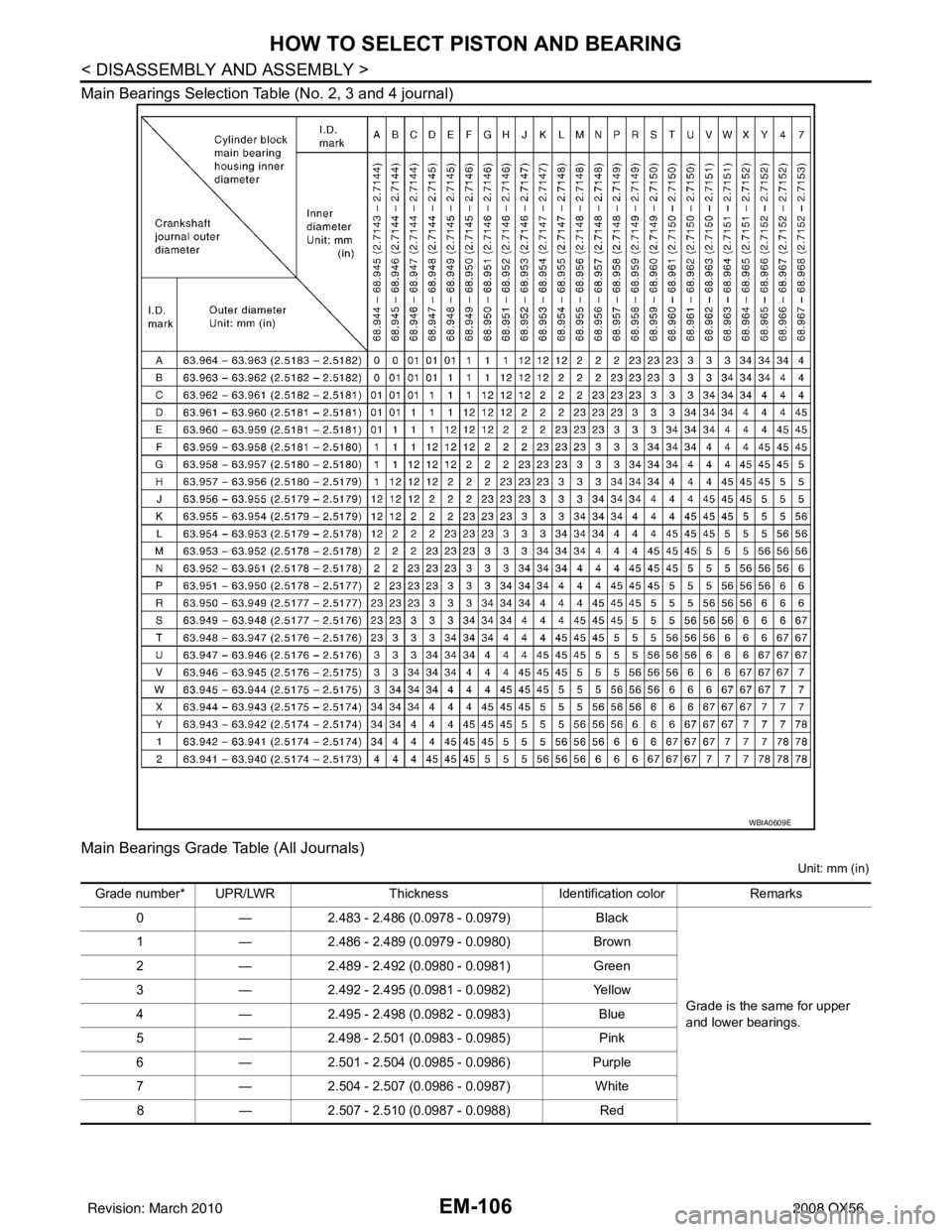
Main Bearings Selection Table (No. 2, 3 and 4 journal)
Main Bearings Grade Table (All Journals)
Unit: mm (in)
WBIA0609E
Grade number* UPR/LWRThickness Identification color Remarks
0 —2.483 - 2.486 (0.0978 - 0.0979) Black
Grade is the same for upper
and lower bearings.
1
—2.486 - 2.489 (0.0979 - 0.0980) Brown
2 —2.489 - 2.492 (0.0980 - 0.0981) Green
3 —2.492 - 2.495 (0.0981 - 0.0982) Yellow
4 —2.495 - 2.498 (0.0982 - 0.0983) Blue
5 —2.498 - 2.501 (0.0983 - 0.0985) Pink
6 —2.501 - 2.504 (0.0985 - 0.0986) Purple
7 —2.504 - 2.507 (0.0986 - 0.0987) White
8 —2.507 - 2.510 (0.0987 - 0.0988) Red
Revision: March 2010 2008 QX56
Page 1910 of 4083
HOW TO SELECT PISTON AND BEARINGEM-107
< DISASSEMBLY AND ASSEMBLY >
C
DE
F
G H
I
J
K L
M A
EM
NP
O
*: Always check with the Parts Department for the latest parts information.
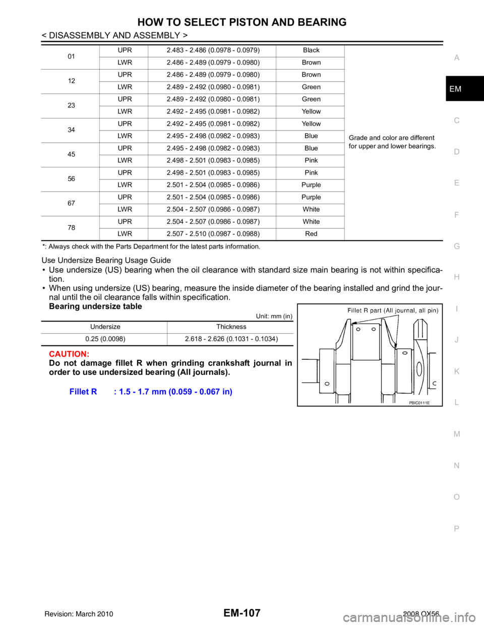
Use Undersize Bearing Usage Guide
• Use undersize (US) bearing when the oil clearance with
standard size main bearing is not within specifica-
tion.
• When using undersize (US) bearing, measure the inside di ameter of the bearing installed and grind the jour-
nal until the oil clearance falls within specification.
Bearing undersize table
Unit: mm (in)
CAUTION:
Do not damage fillet R when grinding crankshaft journal in
order to use undersized bearing (All journals).
01 UPR
2.483 - 2.486 (0.0978 - 0.0979) Black
Grade and color are different
for upper and lower bearings.
LWR
2.486 - 2.489 (0.0979 - 0.0980) Brown
12 UPR
2.486 - 2.489 (0.0979 - 0.0980) Brown
LWR 2.489 - 2.492 (0.0980 - 0.0981) Green
23 UPR
2.489 - 2.492 (0.0980 - 0.0981) Green
LWR 2.492 - 2.495 (0.0981 - 0.0982) Yellow
34 UPR
2.492 - 2.495 (0.0981 - 0.0982) Yellow
LWR 2.495 - 2.498 (0.0982 - 0.0983) Blue
45 UPR
2.495 - 2.498 (0.0982 - 0.0983) Blue
LWR 2.498 - 2.501 (0.0983 - 0.0985) Pink
56 UPR
2.498 - 2.501 (0.0983 - 0.0985) Pink
LWR 2.501 - 2.504 (0.0985 - 0.0986) Purple
67 UPR
2.501 - 2.504 (0.0985 - 0.0986) Purple
LWR 2.504 - 2.507 (0.0986 - 0.0987) White
78 UPR
2.504 - 2.507 (0.0986 - 0.0987) White
LWR 2.507 - 2.510 (0.0987 - 0.0988) Red
UndersizeThickness
0.25 (0.0098) 2.618 - 2.626 (0.1031 - 0.1034)
Fillet R : 1.5 - 1.7 mm (0.059 - 0.067 in)
PBIC0111E
Revision: March 2010 2008 QX56
Page 1920 of 4083
SERVICE DATA AND SPECIFICATIONS (SDS)EM-117
< SERVICE DATA AND SPECIFICATIONS (SDS)
C
DE
F
G H
I
J
K L
M A
EM
NP
O
*: Always check with the Parts Department for the latest parts information.
Undersize
Unit: mm (in)
Main Bearing Oil Clearance
Unit: mm (in)
Connecting Rod Bearing
*: Always check with the Parts Department for the latest parts information.
Undersize
0
—2.483 - 2.486 (0.0978 - 0.0979) Black
Grade is the same for upper
and lower bearings
1
—2.486 - 2.489 (0.0979 - 0.0980) Brown
2 —2.489 - 2.492 (0.0980 - 0.0981) Green
3 —2.492 - 2.495 (0.0981 - 0.0982) Yellow
4 —2.495 - 2.498 (0.0982 - 0.0983) Blue
5 —2.498 - 2.501 (0.0983 - 0.0985) Pink
6 —2.501 - 2.504 (0.0985 - 0.0986) Purple
7 —2.504 - 2.507 (0.0986 - 0.0987) White
8 —2.507 - 2.510 (0.0987 - 0.0988) Red
01 UPR
2.483 - 2.486 (0.0978 - 0.0979) Black
Grade is different for upper and
lower bearings.
LWR
2.486 - 2.489 (0.0979 - 0.0980) Brown
12 UPR
2.486 - 2.489 (0.0979 - 0.0980) Brown
LWR 2.489 - 2.492 (0.0980 - 0.0981) Green
23 UPR
2.489 - 2.492 (0.0980 - 0.0981) Green
LWR 2.492 - 2.495 (0.0981 - 0.0982) Yellow
34 UPR
2.492 - 2.495 (0.0981 - 0.0982) Yellow
LWR 2.495 - 2.498 (0.0982 - 0.0983) Blue
45 UPR
2.495 - 2.498 (0.0982 - 0.0983) Blue
LWR 2.498 - 2.501 (0.0983 - 0.0985) Pink
56 UPR
2.498 - 2.501 (0.0983 - 0.0985) Pink
LWR 2.501 - 2.504 (0.0985 - 0.0986) Purple
67 UPR
2.501 - 2.504 (0.0985 - 0.0986) Purple
LWR 2.504 - 2.507 (0.0986 - 0.0987) White
78 UPR
2.504 - 2.507 (0.0986 - 0.0987) White
LWR 2.507 - 2.510 (0.0987 - 0.0988) Red
UndersizeThickness Main journal diameter
0.25 (0.0098) 2.618 - 2.626 (0.1031 - 0.1034) Grind so that bearing clearance is the specified value.
Items StandardLimit
Main bearing oil clearance No.1 and 5
0.001 - 0.011 (0.00004 - 0.0004) 0.021 (0.0008)
No.2, 3 and 4 0.007 - 0.017 (0.0003 - 0.0007) 0.027 (0.0011)
Grade number*Thickness “T” mm (in) Identification color (mark)
0 1.500 - 1.503 (0.0591 - 0.0592) Black
1 1.503 - 1.506 (0.0592 - 0.0593) Brown
2 1.506 - 1.509 (0.0593 - 0.0594) Green
3 1.509 - 1.512 (0.0594 - 0.0595) Yellow
Revision: March 2010 2008 QX56