Page 2592 of 4083
OIL FILTERLU-11
< ON-VEHICLE MAINTENANCE >
C
DE
F
G H
I
J
K L
M A
LU
NP
O
OIL FILTER
Removal and InstallationINFOID:0000000001538846
REMOVAL
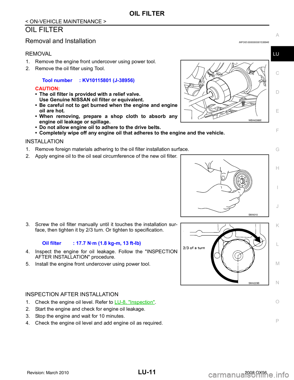
1. Remove the engine front undercover using power tool.
2. Remove the oil filter using Tool.
CAUTION:
• The oil filter is provided with a relief valve.Use Genuine NISSAN oil filter or equivalent.
• Be careful not to get burned when the engine and engine
oil are hot.
• When removing, prepare a s hop cloth to absorb any
engine oil leakage or spillage.
• Do not allow engine oil to adhere to the drive belts.
• Completely wipe off any engine oil that adheres to the engine and the vehicle.
INSTALLATION
1. Remove foreign materials adhering to the oil filter installation surface.
2. Apply engine oil to the oil seal circumference of the new oil filter.
3. Screw the oil filter manually until it touches the installation sur-
face, then tighten it by 2/3 turn. Or tighten to specification.
4. Inspect the engine for oil leakage. Follow the "INSPECTION AFTER INSTALLATION" procedure.
5. Install the engine front undercover using power tool.
INSPECTION AFTER INSTALLATION
1. Check the engine oil level. Refer to LU-8, "Inspection".
2. Start the engine and check for engine oil leakage.
3. Stop the engine and wait for 10 minutes.
4. Check the engine oil level and add engine oil as required. Tool number : KV10115801 (J-38956)
WBIA0388E
SMA010
Oil filter : 17.7 N·m (1.8 kg-m, 13 ft-lb)
SMA229B
Revision: March 2010
2008 QX56
Page 2617 of 4083
ENGINE MAINTENANCEMA-19
< ON-VEHICLE MAINTENANCE >
C
DE
F
G H
I
J
K L
M B
MA
N
O A
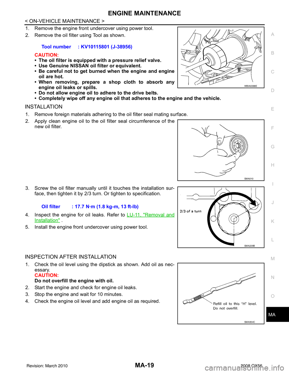
1. Remove the engine front undercover using power tool.
2. Remove the oil filter using Tool as shown.
CAUTION:
• The oil filter is equipped with a pressure relief valve.
• Use Genuine NISSAN oil filter or equivalent.
• Be careful not to get burned when the engine and engine
oil are hot.
• When removing, prepare a s hop cloth to absorb any
engine oil leaks or spills.
• Do not allow engine oil to adhere to the drive belts.
• Completely wipe off any engine oil that adheres to the engine and the vehicle.
INSTALLATION
1. Remove foreign materials adhering to the oil filter seal mating surface.
2. Apply clean engine oil to the oil filter seal circumference of the
new oil filter.
3. Screw the oil filter manually unt il it touches the installation sur-
face, then tighten it by 2/3 turn. Or tighten to specification.
4. Inspect the engine for oil leaks. Refer to LU-11, "
Removal and
Installation" .
5. Install the engine front undercover using power tool.
INSPECTION AFTER INSTALLATION
1. Check the oil level using the dipstick as shown. Add oil as nec- essary.
CAUTION:
Do not overfill th e engine with oil.
2. Start the engine and check for engine oil leaks.
3. Stop the engine and wait for 10 minutes.
4. Check the engine oil level and add engine oil as required. Tool number : KV10115801 (J-38956)
WBIA0388E
SMA010
Oil filter : 17.7 N·m (1.8 kg-m, 13 ft-lb)
SMA229B
SMA954C
Revision: March 2010
2008 QX56
Page 2630 of 4083
MA-32
< ON-VEHICLE MAINTENANCE >
CHASSIS AND BODY MAINTENANCE
• Check the axle and suspension nuts and bolts for looseness.
• Check the strut and shock absorber for oil leakage or other damage.
• Check the suspension ball joints for grease leakage and ball joint dust cover for cracks or other damage.
DRIVE SHAFT
Check the boots and drive shaft for cracks, wear, damage, and
grease leakage.
SFA901
Revision: March 20102008 QX56
Page 2652 of 4083
MWI
METER SYSTEMMWI-7
< FUNCTION DIAGNOSIS >
C
DE
F
G H
I
J
K L
M B A
O P
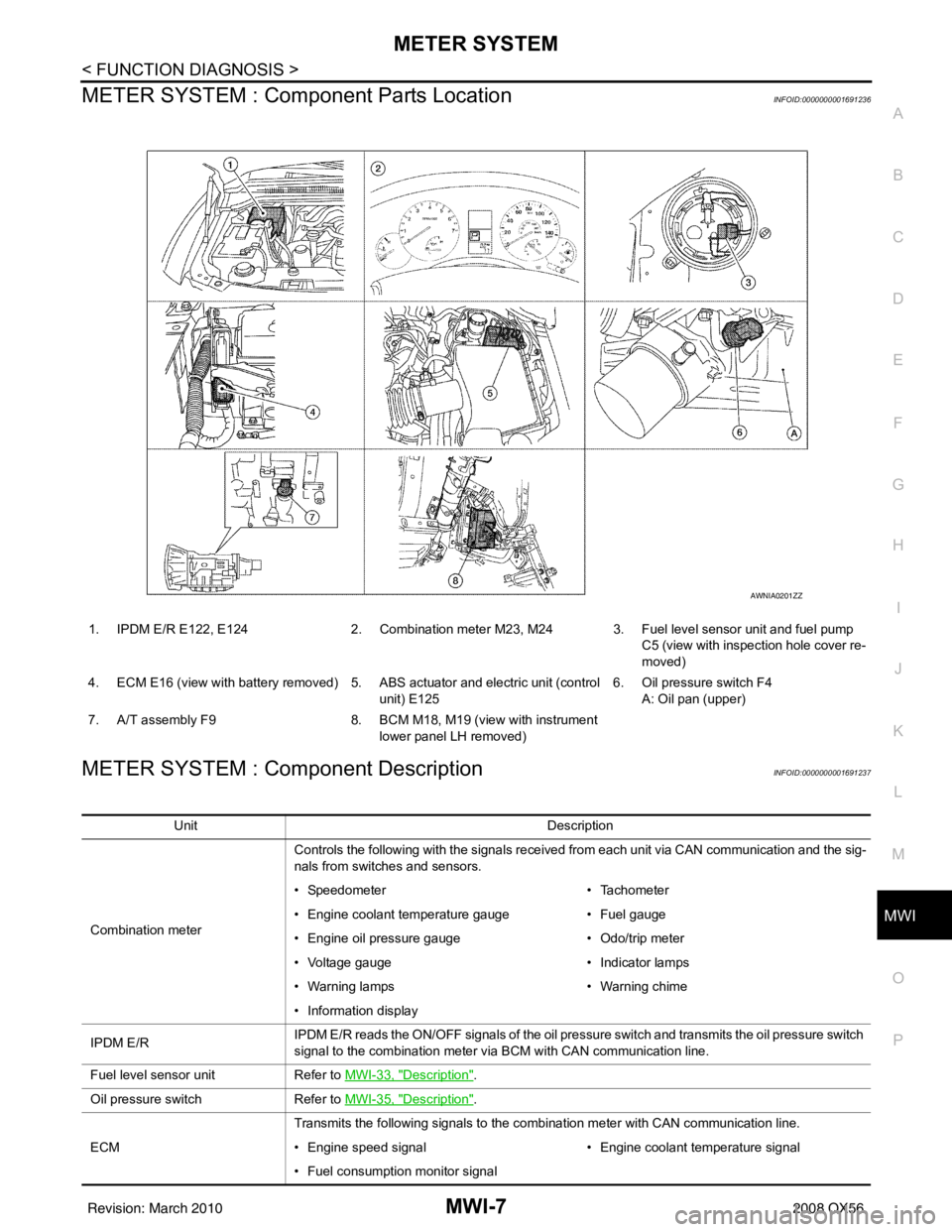
METER SYSTEM : Com ponent Parts LocationINFOID:0000000001691236
METER SYSTEM : Component DescriptionINFOID:0000000001691237
1. IPDM E/R E122, E124 2. Combination meter M23, M24 3. Fuel level sensor unit and fuel pump
C5 (view with inspection hole cover re-
moved)
4. ECM E16 (view with battery removed) 5. ABS actuator and electric unit (control unit) E1256. Oil pressure switch F4
A: Oil pan (upper)
7. A/T assembly F9 8. BCM M18, M19 (view with instrument
lower panel LH removed)
AWNIA0201ZZ
Unit Description
Combination meter Controls the following with the signals received from each unit via CAN communication and the sig-
nals from switches and sensors.
• Speedometer
• Tachometer
• Engine coolant temperature gauge • Fuel gauge
• Engine oil pressure gauge • Odo/trip meter
• Voltage gauge • Indicator lamps
• Warning lamps • Warning chime
• Information display
IPDM E/R IPDM E/R reads the ON/OFF signals of the oil pressure switch and transmits the oil pressure switch
signal to the combination meter via BCM with CAN communication line.
Fuel level sensor unit Refer to MWI-33, "
Description".
Oil pressure switch Refer to MWI-35, "
Description".
ECM Transmits the following signals to the combination meter with CAN communication line.
• Engine speed signal
• Engine coolant temperature signal
• Fuel consumption monitor signal
Revision: March 2010 2008 QX56
Page 2653 of 4083
MWI-8
< FUNCTION DIAGNOSIS >
METER SYSTEM
SPEEDOMETER
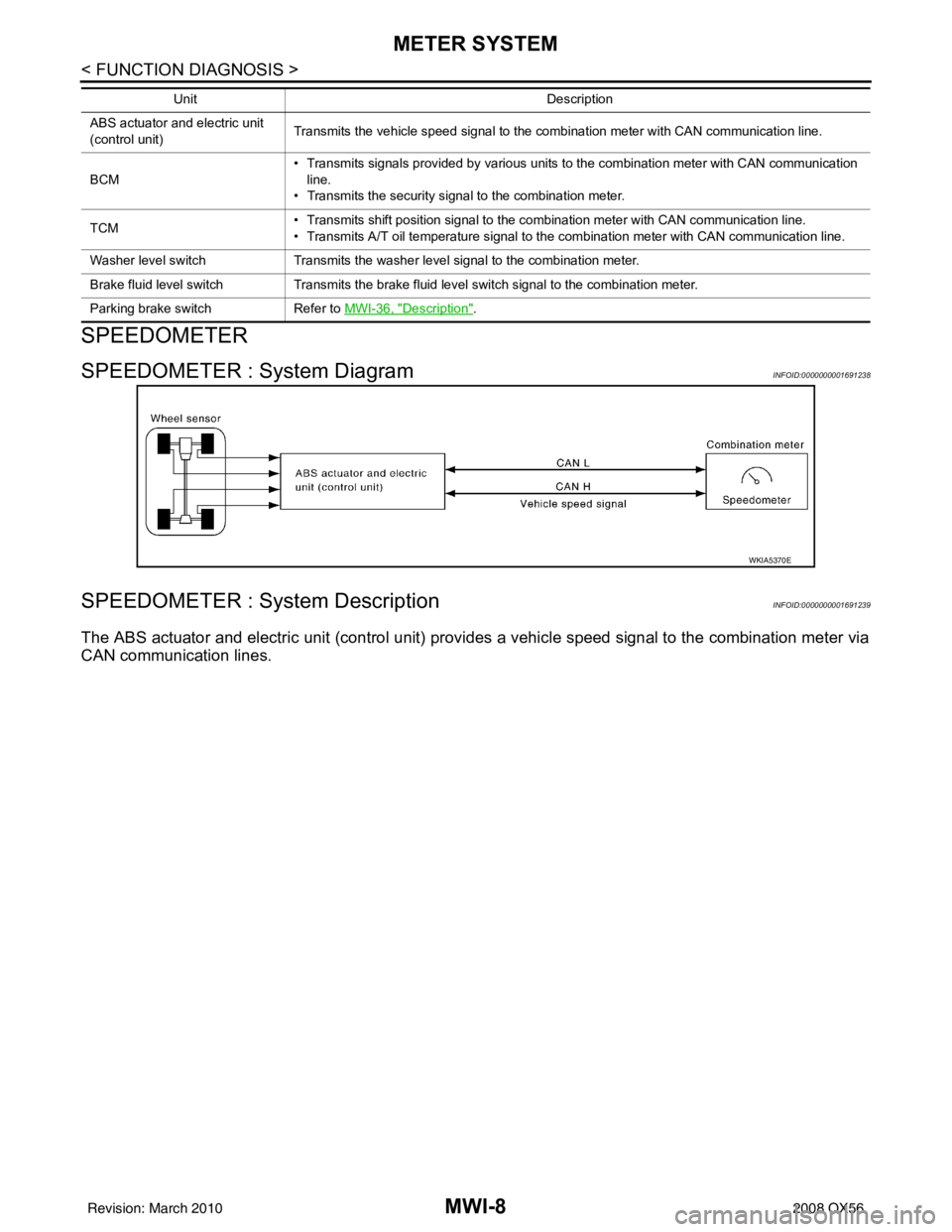
SPEEDOMETER : System DiagramINFOID:0000000001691238
SPEEDOMETER : System DescriptionINFOID:0000000001691239
The ABS actuator and electric unit (control unit) provides a vehicle speed signal to the combination meter via
CAN communication lines.
ABS actuator and electric unit
(control unit) Transmits the vehicle speed signal to the combination meter with CAN communication line.
BCM • Transmits signals provided by various units to the combination meter with CAN communication
line.
• Transmits the security signal to the combination meter.
TCM • Transmits shift position signal to the combination meter with CAN communication line.
• Transmits A/T oil temperature signal to the combination meter with CAN communication line.
Washer level switch Transmits the washer level signal to the combination meter.
Brake fluid level switch Transmits the brake fluid level switch signal to the combination meter.
Parking brake switch Refer to MWI-36, "
Description".
Unit
Description
WKIA5370E
Revision: March 2010 2008 QX56
Page 2654 of 4083
MWI
METER SYSTEMMWI-9
< FUNCTION DIAGNOSIS >
C
DE
F
G H
I
J
K L
M B A
O P
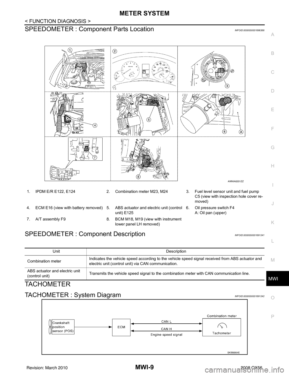
SPEEDOMETER : Compone nt Parts LocationINFOID:0000000001696366
SPEEDOMETER : Component DescriptionINFOID:0000000001691241
TACHOMETER
TACHOMETER : System DiagramINFOID:0000000001691242
1. IPDM E/R E122, E124 2. Combination meter M23, M24 3. Fuel level sensor unit and fuel pump
C5 (view with inspection hole cover re-
moved)
4. ECM E16 (view with battery removed) 5. ABS actuator and electric unit (control unit) E1256. Oil pressure switch F4
A: Oil pan (upper)
7. A/T assembly F9 8. BCM M18, M19 (view with instrument
lower panel LH removed)
AWNIA0201ZZ
Unit Description
Combination meter Indicates the vehicle speed according to the vehicle speed signal received from ABS actuator and
electric unit (control unit) via CAN communication.
ABS actuator and electric unit
(control unit) Transmits the vehicle speed signal to the combination meter with CAN communication line.
SKIB6904E
Revision: March 2010
2008 QX56
Page 2655 of 4083
MWI-10
< FUNCTION DIAGNOSIS >
METER SYSTEM
TACHOMETER : System Description
INFOID:0000000001691243
The tachometer indicates engine speed in revolutions per minute (rpm).
The ECM provides an engine speed signal to the co mbination meter via CAN communication lines.
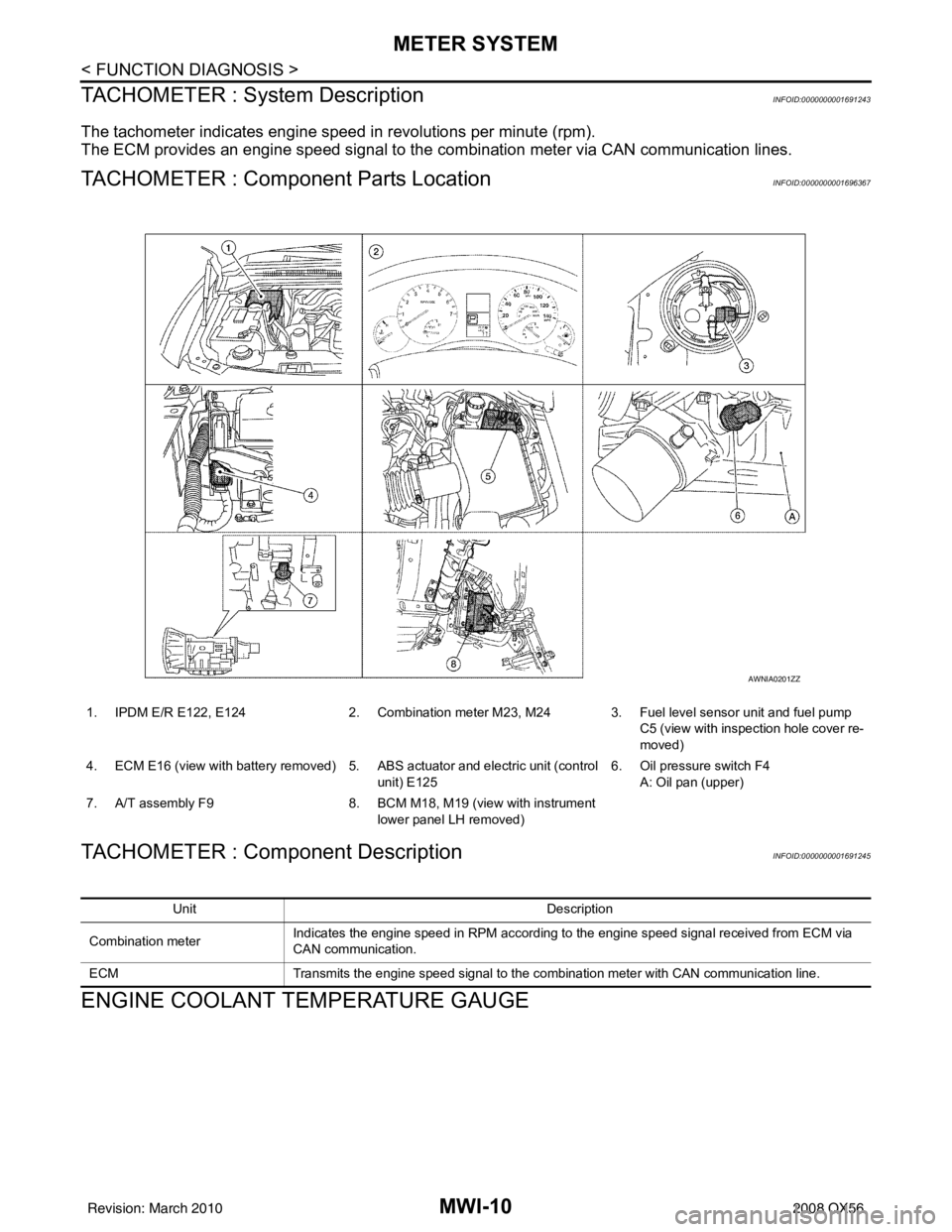
TACHOMETER : Component Parts LocationINFOID:0000000001696367
TACHOMETER : Component DescriptionINFOID:0000000001691245
ENGINE COOLANT TEMPERATURE GAUGE
1. IPDM E/R E122, E1242. Combination meter M23, M24 3. Fuel level sensor unit and fuel pump
C5 (view with inspection hole cover re-
moved)
4. ECM E16 (view with battery removed) 5. ABS actuator and electric unit (control
unit) E125 6. Oil pressure switch F4
A: Oil pan (upper)
7. A/T assembly F9 8. BCM M18, M19 (view with instrument
lower panel LH removed)
AWNIA0201ZZ
Unit Description
Combination meter Indicates the engine speed in RPM according to the engine speed signal received from ECM via
CAN communication.
ECM Transmits the engine speed signal to the combination meter with CAN communication line.
Revision: March 2010 2008 QX56
Page 2656 of 4083
MWI
METER SYSTEMMWI-11
< FUNCTION DIAGNOSIS >
C
DE
F
G H
I
J
K L
M B A
O P
ENGINE COOLANT TEMPERATURE GAUGE : System DiagramINFOID:0000000001691246
ENGINE COOLANT TEMPERATURE GAUGE : System DescriptionINFOID:0000000001691247
The engine coolant temperature gauge indicates the engine coolant temperature.
The ECM provides an engine coolant temperature signal to the combination meter via CAN communication
lines.
ENGINE COOLANT TEMPERATURE GA UGE : Component Parts Location
INFOID:0000000001696368
SKIB6905E
1. IPDM E/R E122, E124 2. Combination meter M23, M24 3. Fuel level sensor unit and fuel pump
C5 (view with inspection hole cover re-
moved)
4. ECM E16 (view with battery removed) 5. ABS actuator and electric unit (control unit) E1256. Oil pressure switch F4
A: Oil pan (upper)
7. A/T assembly F9 8. BCM M18, M19 (view with instrument
lower panel LH removed)
AWNIA0201ZZ
Revision: March 2010 2008 QX56