2008 INFINITI QX56 wiring diagram
[x] Cancel search: wiring diagramPage 3550 of 4083
TM-3
CEF
G H
I
J
K L
M A
B
TM
N
O P
P1752 INPUT CLUTCH SOLENOID .............. ....80
Description .......................................................... ....80
CONSULT-III Reference Value in Data Monitor
Mode ................................................................... ....
80
On Board Diagnosis Logic ......................................80
Possible Cause .......................................................80
DTC Confirmation Procedure ..................................80
Diagnosis Procedure ...............................................80
P1757 FRONT BRAKE SOLENOID ...................82
Description .......................................................... ....82
CONSULT-III Reference Value in Data Monitor
Mode ................................................................... ....
82
On Board Diagnosis Logic ......................................82
Possible Cause .......................................................82
DTC Confirmation Procedure ..................................82
Diagnosis Procedure ...............................................82
P1762 DIRECT CLUTCH SOLENOID ................84
Description .......................................................... ....84
CONSULT-III Reference Value in Data Monitor
Mode ................................................................... ....
84
On Board Diagnosis Logic ......................................84
Possible Cause .......................................................84
DTC Confirmation Procedure ..................................84
Diagnosis Procedure ...............................................84
P1767 HIGH AND LOW REVERSE CLUTCH
SOLENOID .........................................................
86
Description .......................................................... ....86
CONSULT-III Reference Value in Data Monitor
Mode ................................................................... ....
86
On Board Diagnosis Logic ......................................86
Possible Cause .......................................................86
DTC Confirmation Procedure ..................................86
Diagnosis Procedure ...............................................86
P1772 LOW COAST BRAKE SOLENOID .........88
Description .......................................................... ....88
CONSULT-III Reference Value in Data Monitor
Mode ................................................................... ....
88
On Board Diagnosis Logic ......................................88
Possible Cause .......................................................88
DTC Confirmation Procedure ..................................88
Diagnosis Procedure ...............................................88
P1774 LOW COAST BRAKE SOLENOID .........90
Description .......................................................... ....90
CONSULT-III Reference Value in Data Monitor
Mode ................................................................... ....
90
On Board Diagnosis Logic ......................................90
Possible Cause .......................................................90
DTC Confirmation Procedure ..................................90
Diagnosis Procedure ...............................................90
MAIN POWER SUPPLY AND GROUND CIR-
CUIT ....................................................................
92
Diagnosis Procedure ........................................... ....92
CLOSED THROTTLE POSITION AND WIDE
OPEN THROTTLE POSITION CIRCUIT ...........
94
CONSULT-III Reference Value in Data Monitor
Mode .................................................................... ....
94
Diagnosis Procedure ...............................................94
BRAKE SIGNAL CIRCUIT ................................95
CONSULT-III Reference Va lue in Data Monitor
Mode .................................................................... ....
95
Diagnosis Procedure ...............................................95
TOW MODE SWITCH .......................................96
Description ...............................................................96
Diagnosis Procedure ...............................................96
A/T SHIFT LOCK SYSTEM ...............................97
Wiring Diagram - A/T Shift Lock System .................97
Terminals And Reference Values ..........................100
Component Description ....................................... ..100
ECU DIAGNOSIS .......................................103
TCM .................................................................103
Reference Value .................................................. ..103
Wiring Diagram — A/T CONTROL SYSTEM — .. ..105
Fail-Safe .............................................................. ..114
DTC Inspection Priority Chart ................................116
DTC No. Index .......................................................116
DTC Alphabetical Index .........................................117
SYMPTOM DIAGNOSIS ............................118
SYSTEM SYMPTOM .......................................118
A/T Check Indicator Lamp Does Not Come On ... ..118
Engine Cannot Be Started in "P" or "N" Position ...118
In "P" Position, Vehicle Moves When Pushed .......119
In "N" Position, Vehicle Moves ..............................119
Large Shock("N" to "D" Position) ...........................121
Vehicle Does Not Creep Backward in "R" Position ..123
Vehicle Does Not Creep Forward in "D" Position ..125
Vehicle Cannot Be Started from D1 ......................128
A/T Does Not Shift: D1→D2 ..................................130
A/T Does Not Shift: D2→ D3 ..................................131
A/T Does Not Shift: D3→ D4 ..................................133
A/T Does Not Shift: D4→ D5 ..................................135
A/T Does Not Perform Lock-up ........................... ..137
A/T Does Not Hold Lock-up Condition ...................139
Lock-up Is Not Released .......................................140
Engine Speed Does Not Return to Idle .................141
A/T Does Not Shift: 5GR → 4GR ........................ ..142
A/T Does Not Shift: 4GR → 3GR ........................ ..144
A/T Does Not Shift: 3GR → 2GR ........................ ..146
A/T Does Not Shift: 2GR → 1GR ........................ ..147
Vehicle Does Not Decelerate By Engine Brake ... ..149
Symptom Table .....................................................151
PRECAUTION ............................................173
PRECAUTIONS ...............................................173
Revision: March 2010 2008 QX56
Page 3568 of 4083
A/T CONTROL SYSTEMTM-21
< FUNCTION DIAGNOSIS >
CEF
G H
I
J
K L
M A
B
TM
N
O P
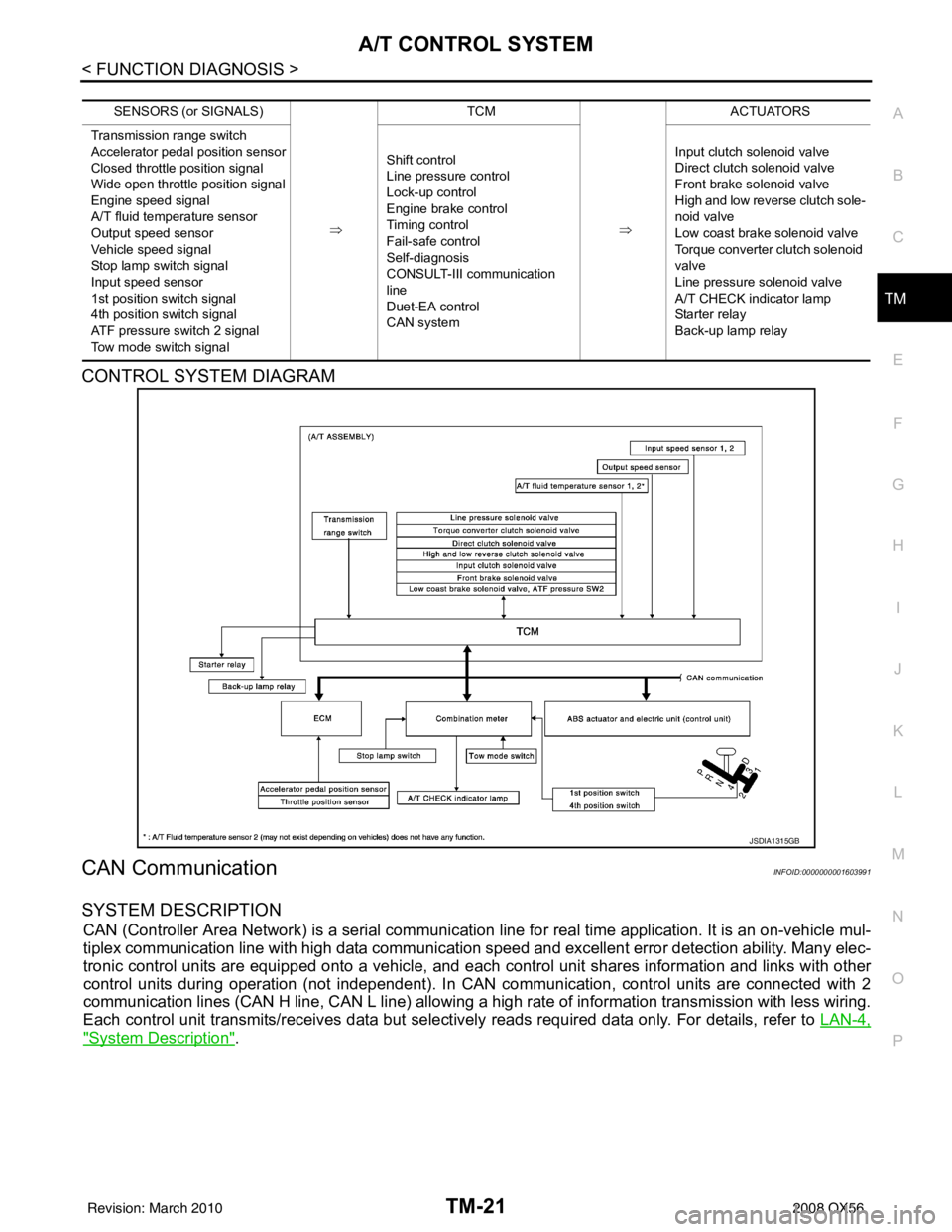
CONTROL SYSTEM DIAGRAM
CAN CommunicationINFOID:0000000001603991
SYSTEM DESCRIPTION
CAN (Controller Area Network) is a serial communication line for real time application. It is an on-vehicle mul-
tiplex communication line with high data communication speed and excellent error detection ability. Many elec-
tronic control units are equipped onto a vehicle, and each control unit shares information and links with other
control units during operation (not independent). In CAN communication, control units are connected with 2
communication lines (CAN H line, CAN L line) allowing a high rate of information transmission with less wiring.
Each control unit transmits/receives data but selectively reads required data only. For details, refer to LAN-4,
"System Description".
SENSORS (or SIGNALS)
⇒TCM
⇒ACTUATORS
Transmission range switch
Accelerator pedal position sensor
Closed throttle position signal
Wide open throttle position signal
Engine speed signal
A/T fluid temperature sensor
Output speed sensor
Vehicle speed signal
Stop lamp switch signal
Input speed sensor
1st position switch signal
4th position switch signal
ATF pressure switch 2 signal
Tow mode switch signal Shift control
Line pressure control
Lock-up control
Engine brake control
Timing control
Fail-safe control
Self-diagnosis
CONSULT-III co
mmunication
line
Duet-EA control
CAN system Input clutch solenoid valve
Direct clutch solenoid valve
Front brake solenoid valve
High and low reverse clutch sole-
noid valve
Low coast brake solenoid valve
Torque converter clutch solenoid
valve
Line pressure solenoid valve
A/T CHECK indicator lamp
Starter relay
Back-up lamp relay
JSDIA1315GB
Revision: March 2010
2008 QX56
Page 3644 of 4083
A/T SHIFT LOCK SYSTEMTM-97
< COMPONENT DIAGNOSIS >
CEF
G H
I
J
K L
M A
B
TM
N
O P
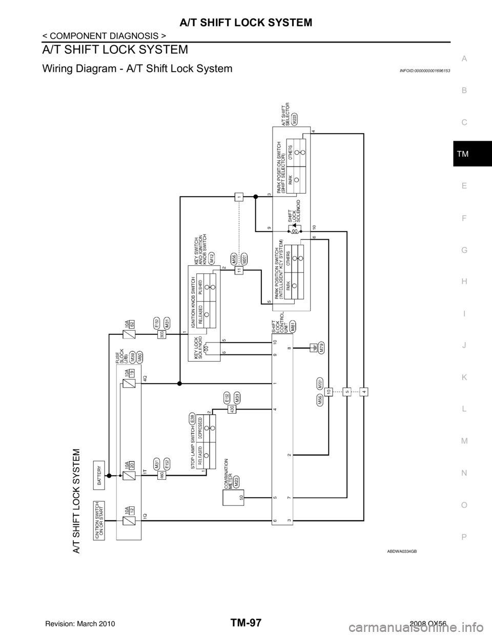
A/T SHIFT LOCK SYSTEM
Wiring Diagram - A/ T Shift Lock SystemINFOID:0000000001696153
ABDWA0334GB
Revision: March 2010 2008 QX56
Page 3652 of 4083
TCM
TM-105
< ECU DIAGNOSIS >
C EF
G H
I
J
K L
M A
B
TM
N
O P
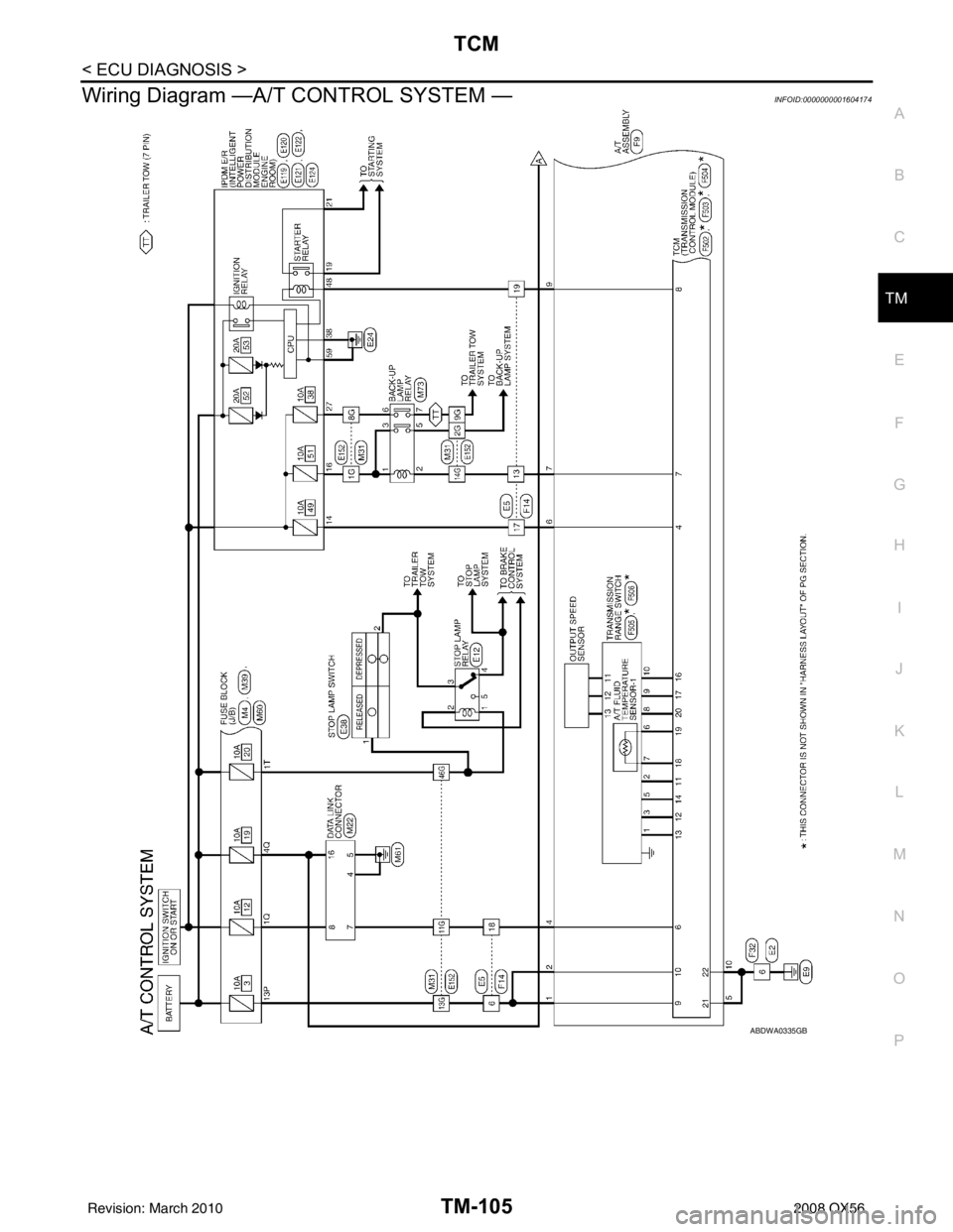
Wiring Diagram —A/T CONTROL SYSTEM —INFOID:0000000001604174
ABDWA0335GB
Revision: March 2010 2008 QX56
Page 3857 of 4083
HEATER & COOLING UNIT ASSEMBLYVTL-17
< ON-VEHICLE REPAIR >
C
DE
F
G H
J
K L
M A
B
VTL
N
O P
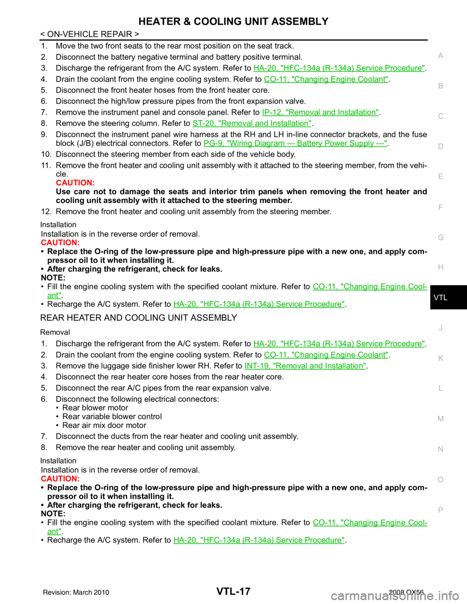
1. Move the two front seats to the rear most position on the seat track.
2. Disconnect the battery negative terminal and battery positive terminal.
3. Discharge the refrigerant from the A/C system. Refer to HA-20, "
HFC-134a (R-134a) Service Procedure".
4. Drain the coolant from the engine cooling system. Refer to CO-11, "
Changing Engine Coolant".
5. Disconnect the front heater hoses from the front heater core.
6. Disconnect the high/low pressure pipes from the front expansion valve.
7. Remove the instrument panel and console panel. Refer to IP-12, "
Removal and Installation".
8. Remove the steering column. Refer to ST-20, "
Removal and Installation".
9. Disconnect the instrument panel wire harness at t he RH and LH in-line connector brackets, and the fuse
block (J/B) electrical connectors. Refer to PG-9, "
Wiring Diagram — Battery Power Supply —".
10. Disconnect the steering member from each side of the vehicle body.
11. Remove the front heater and cooling unit assembly with it attached to the steering member, from the vehi- cle.
CAUTION:
Use care not to damage the seats and interior trim panels when removing the front heater and
cooling unit assembly with it at tached to the steering member.
12. Remove the front heater and cooling uni t assembly from the steering member.
Installation
Installation is in the reverse order of removal.
CAUTION:
• Replace the O-ring of the low-pressure pipe and high-pressure pipe with a new one, and apply com-
pressor oil to it when installing it.
• After charging the refrigerant, check for leaks.
NOTE:
• Fill the engine cooling system with the specified coolant mixture. Refer to CO-11, "
Changing Engine Cool-
ant".
• Recharge the A/C system. Refer to HA-20, "
HFC-134a (R-134a) Service Procedure".
REAR HEATER AND COOLING UNIT ASSEMBLY
Removal
1. Discharge the refrigerant from the A/C system. Refer to HA-20, "HFC-134a (R-134a) Service Procedure".
2. Drain the coolant from the engine cooling system. Refer to CO-11, "
Changing Engine Coolant".
3. Remove the luggage side finisher lower RH. Refer to INT-19, "
Removal and Installation".
4. Disconnect the rear heater core hoses from the rear heater core.
5. Disconnect the rear A/C pipes from the rear expansion valve.
6. Disconnect the following electrical connectors: • Rear blower motor
• Rear variable blower control
• Rear air mix door motor
7. Disconnect the ducts from the rear heater and cooling unit assembly.
8. Remove the rear heater and cooling unit assembly.
Installation
Installation is in the reverse order of removal.
CAUTION:
• Replace the O-ring of the low-pressure pipe and high-pressure pipe with a new one, and apply com- pressor oil to it when installing it.
• After charging the refrigerant, check for leaks.
NOTE:
• Fill the engine cooling system with the specified coolant mixture. Refer to CO-11, "
Changing Engine Cool-
ant".
• Recharge the A/C system. Refer to HA-20, "
HFC-134a (R-134a) Service Procedure".
Revision: March 2010 2008 QX56
Page 3879 of 4083

WCS-2
WARNING CHIME SYSTEM .............................24
Wiring Diagram .................................................... ...24
ECU DIAGNOSIS ..................................... ...29
COMBINATION METER ................................. ...29
Reference Value .................................................. ...29
Wiring Diagram .......................................................31
Fail Safe .................................................................48
DTC Index ..............................................................49
BCM (BODY CONTROL MODULE) ..................51
Reference Value .................................................. ...51
Terminal Layout ......................................................53
Physical Values ......................................................53
Wiring Diagram .......................................................59
Fail Safe .................................................................62
DTC Inspection Priority Chart ..............................63
DTC Index ........................................................... ...63
SYMPTOM DIAGNOSIS .............................65
THE LIGHT REMINDER WARNING DOES
NOT SOUND ................................................... ...
65
Description ........................................................... ...65
Diagnosis Procedure ...............................................65
THE SEAT BELT WARNING CONTINUES
SOUNDING, OR DOES NOT SOUND ...............
66
Description ........................................................... ...66
Diagnosis Procedure ...............................................66
THE KEY WARNING DOES NOT SOUND .......67
Description ........................................................... ...67
Diagnosis Procedure ...............................................67
PRECAUTION ............................................68
PRECAUTIONS .............................................. ...68
Precaution for Supplemental Restraint System
(SRS) "AIR BAG" and "SEAT BELT PRE-TEN-
SIONER" .............................................................. ...
68
Precaution Necessary for Steering Wheel Rota-
tion After Battery Disconnect ..................................
68
Revision: March 2010 2008 QX56
Page 3901 of 4083
WCS-24
< COMPONENT DIAGNOSIS >
WARNING CHIME SYSTEM
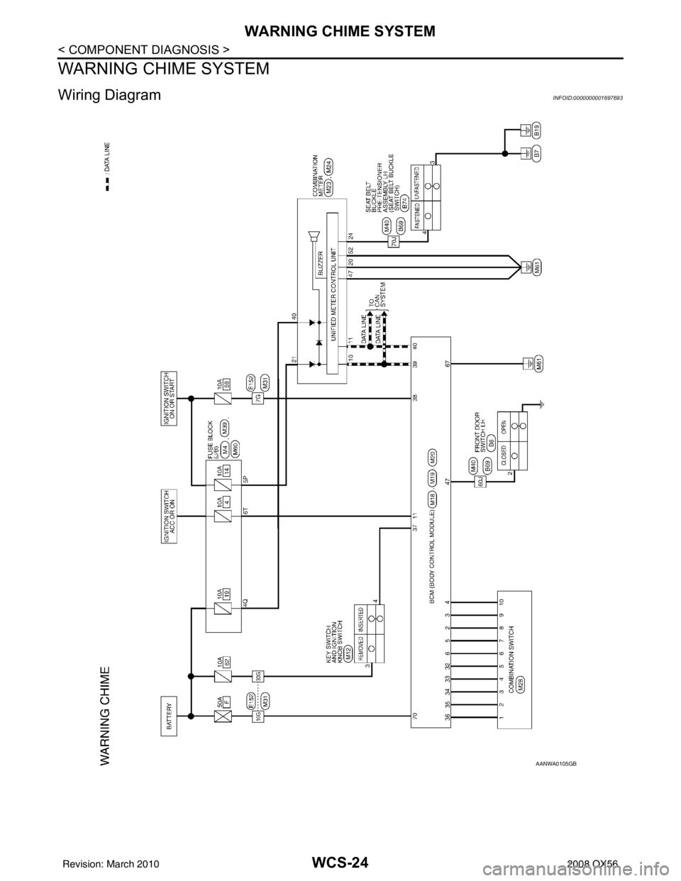
WARNING CHIME SYSTEM
Wiring DiagramINFOID:0000000001697693
AANWA0105GB
Revision: March 20102008 QX56
Page 3908 of 4083
WCS
COMBINATION METERWCS-31
< ECU DIAGNOSIS >
C
DE
F
G H
I
J
K L
M B A
O P
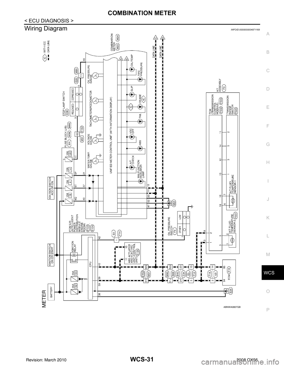
Wiring DiagramINFOID:0000000004871169
ABNWA0807GB
Revision: March 2010 2008 QX56