Page 2895 of 4083
PWC-54
< ECU DIAGNOSIS >
BCM (BODY CONTROL MODULE)
Te r m i n a lWire
color Signal name Signal
input/
output Measuring condition
Reference value or waveform
(Approx.)
Ignition
switch Operation or condition
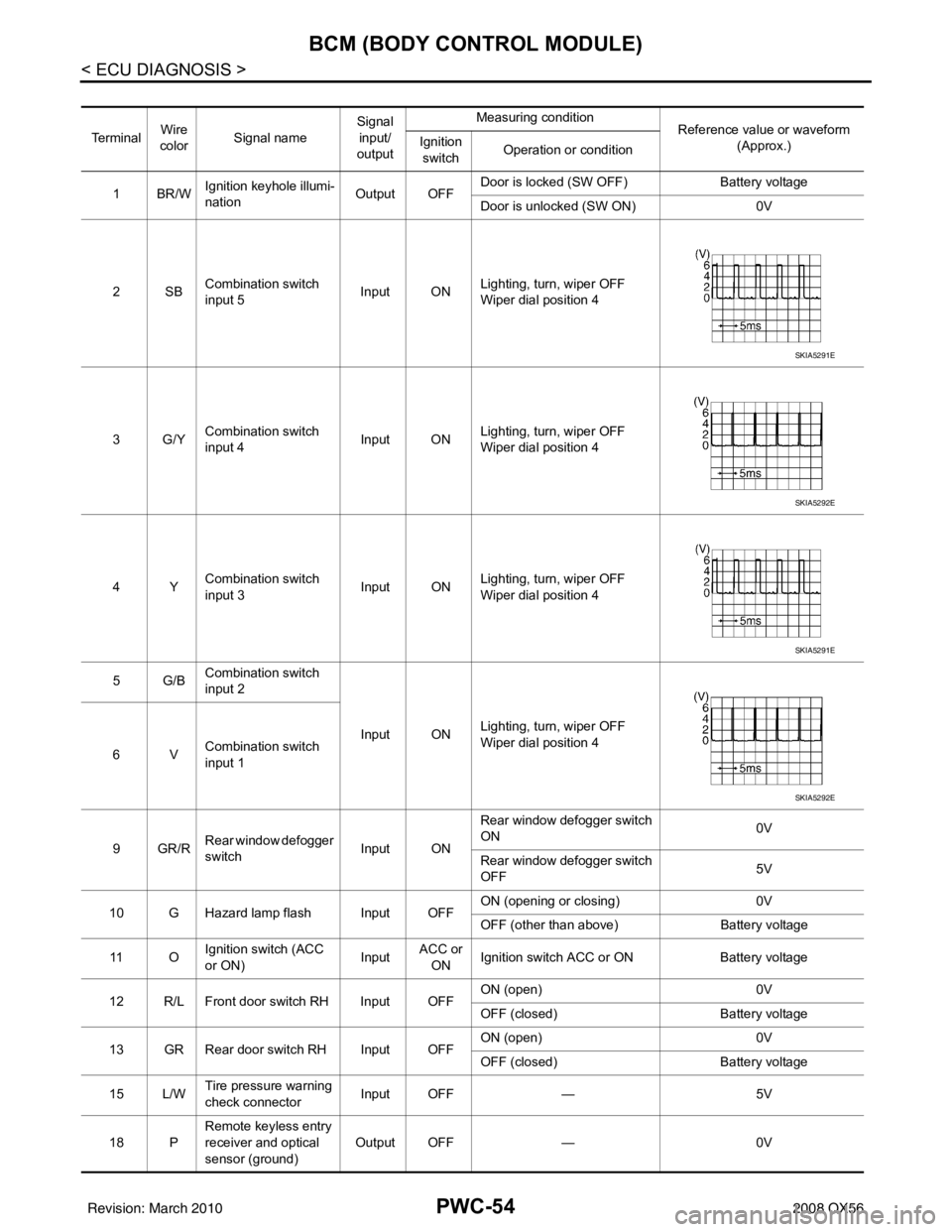
1BR/W Ignition keyhole illumi-
nation Output OFFDoor is locked (SW OFF)
Battery voltage
Door is unlocked (SW ON) 0V
2SB Combination switch
input 5 Input ON
Lighting, turn, wiper OFF
Wiper dial position 4
3G/Y Combination switch
input 4 Input ONLighting, turn, wiper OFF
Wiper dial position 4
4Y Combination switch
input 3 Input ON
Lighting, turn, wiper OFF
Wiper dial position 4
5G/B Combination switch
input 2
Input ONLighting, turn, wiper OFF
Wiper dial position 4
6V Combination switch
input 1
9GR/R Rear window defogger
switch
Input ONRear window defogger switch
ON
0V
Rear window defogger switch
OFF 5V
10 G Hazard lamp flash Input OFF ON (opening or closing)
0V
OFF (other than above) Battery voltage
11 O Ignition switch (ACC
or ON)
InputACC or
ON Ignition switch ACC or ON
Battery voltage
12 R/L Front door switch RH Input OFF ON (open)
0V
OFF (closed) Battery voltage
13 GR Rear door switch RH Input OFF ON (open)
0V
OFF (closed) Battery voltage
15 L/W Tire pressure warning
check connector
Input OFF
—5V
18 P Remote keyless entry
receiver and optical
sensor (ground)
Output OFF
—0V
SKIA5291E
SKIA5292E
SKIA5291E
SKIA5292E
Revision: March 2010 2008 QX56
Page 2898 of 4083
BCM (BODY CONTROL MODULE)PWC-57
< ECU DIAGNOSIS >
C
DE
F
G H
I
J
L
M A
B
PWC
N
O P
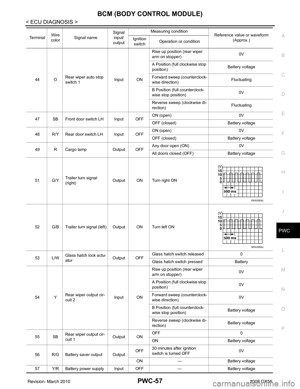
44 O Rear wiper auto stop
switch 1 Input ONRise up position (rear wiper
arm on stopper)
0V
A Position (full clockwise stop
position) Battery voltage
Forward sweep (counterclock-
wise direction) Fluctuating
B Position (full counterclock-
wise stop position) 0V
Reverse sweep (clockwise di-
rection) Fluctuating
47 SB Front door switch LH Input OFF ON (open)
0V
OFF (closed) Battery voltage
48 R/Y Rear door switch LH Input OFF ON (open)
0V
OFF (closed) Battery voltage
49 R Cargo lamp Output OFFAny door open (ON)
0V
All doors closed (OFF) Battery voltage
51 G/Y Trailer turn signal
(right) Output ON Turn right ON
52 G/B Trailer turn signal (left) Output ON Turn left ON
53 L/W Glass hatch lock actu-
ator
Output OFFGlass hatch switch released
0
Glass hatch switch pressed Battery
54 Y Rear wiper output cir-
cuit 2 Input ONRise up position (rear wiper
arm on stopper)
0V
A Position (full clockwise stop
position) 0V
Forward sweep (counterclock-
wise direction) 0V
B Position (full counterclock-
wise stop position) Battery voltage
Reverse sweep (clockwise di-
rection) Battery voltage
55 SB Rear wiper output cir-
cuit 1 Output ONOFF
0
ON Battery voltage
56 R/G Battery saver output Output OFF
30 minutes after ignition
switch is turned OFF 0V
ON — Battery voltage
57 Y/R Battery power supply Input OFF —Battery voltage
Te r m i n a l
Wire
color Signal name Signal
input/
output Measuring condition
Reference value or waveform
(Approx.)
Ignition
switch Operation or condition
SKIA3009J
SKIA3009J
Revision: March 2010
2008 QX56
Page 2899 of 4083
PWC-58
< ECU DIAGNOSIS >
BCM (BODY CONTROL MODULE)
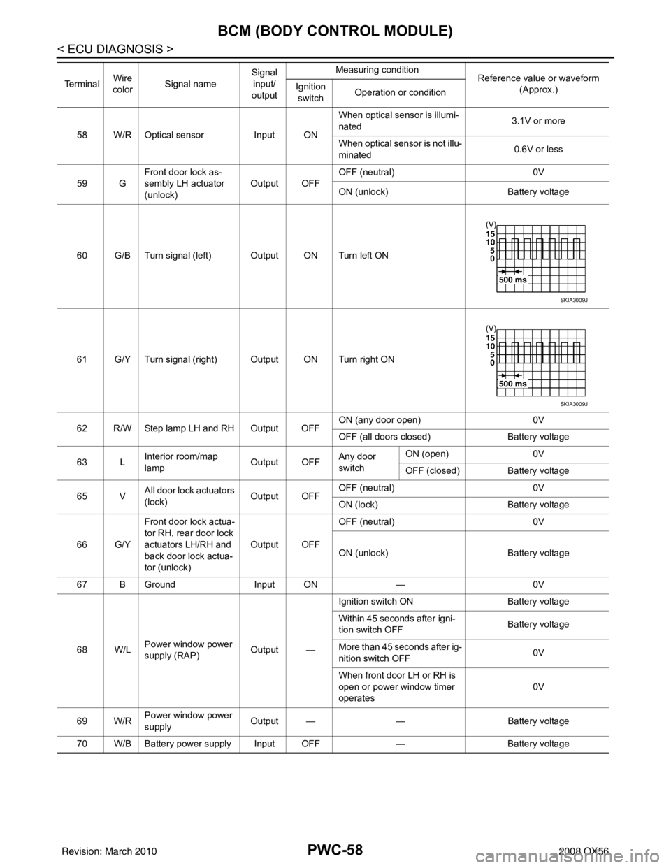
58 W/R Optical sensorInput ONWhen optical sensor is illumi-
nated
3.1V or more
When optical sensor is not illu-
minated 0.6V or less
59 G Front door lock as-
sembly LH actuator
(unlock) Output OFF
OFF (neutral)
0V
ON (unlock) Battery voltage
60 G/B Turn signal (left) Output ON Turn left ON
61 G/Y Turn signal (right) Output ON Turn right ON
62 R/W Step lamp LH and RH Output OFF ON (any door open)
0V
OFF (all doors closed) Battery voltage
63 L Interior room/map
lamp Output OFFAny door
switchON (open)
0V
OFF (closed) Battery voltage
65 V All door lock actuators
(lock) Output OFFOFF (neutral)
0V
ON (lock) Battery voltage
66 G/Y Front door lock actua-
tor RH, rear door lock
actuators LH/RH and
back door lock actua-
tor (unlock) Output OFF
OFF (neutral)
0V
ON (unlock) Battery voltage
67 B Ground Input ON—0V
68 W/L Power window power
supply (RAP) Output —Ignition switch ON
Battery voltage
Within 45 seconds after igni-
tion switch OFF Battery voltage
More than 45 seconds after ig-
nition switch OFF 0V
When front door LH or RH is
open or power window timer
operates 0V
69 W/R Power window power
supply
Output —
—Battery voltage
70 W/B Battery power supply Input OFF —Battery voltage
Te r m i n a l
Wire
color Signal name Signal
input/
output Measuring condition
Reference value or waveform
(Approx.)
Ignition
switch Operation or condition
SKIA3009J
SKIA3009J
Revision: March 2010
2008 QX56
Page 2906 of 4083

POWER WINDOW MAIN SWITCHPWC-65
< ECU DIAGNOSIS >
C
DE
F
G H
I
J
L
M A
B
PWC
N
O P
POWER WINDOW MAIN SWITCH
Reference Value INFOID:0000000001735737
TERMINAL LAYOUT
PHYSICAL VALUES
MAIN POWER WINDOW AND DOOR LOCK/UNLOCK SWITCH
LIIA2455E
Te r m i n a l N o . (Wire color) Description
ConditionVoltage [V]
(Approx.)
+ – Signal name Input/
Output
2
(W/B) Ground Encoder ground
—— 0
4
(L) Ground Door key cylinder switch LH
LOCK signal InputKey position
(Neutral
→ Locked) 5
→ 0
6
(R) Ground Door key cylinder switch LH
UNLOCK signal
InputKey position
(Neutral
→ Unlocked) 5
→ 0
8
(G/R) 11Front door power window mo-
tor LH UP signal
OutputWhen front LH switch in
power window main switch
is operated UP.
Battery voltage
9
(O) 2 Encoder pulse signal 2 Input
When power window mo-
tor operates.
10
(W/L) Ground RAP signal
InputIGN SW ON
Battery voltage
Within 45 second after ig-
nition switch is turned to
OFF. Battery voltage
When front LH or RH door
is opened during retained
power operation. 0
11
(G/W) 8Front door power window mo-
tor LH DOWN signal OutputWhen front LH switch in
power window main switch
is operated DOWN. Battery voltage
JMKIA0070GB
Revision: March 2010
2008 QX56
Page 2921 of 4083
PWC-80
< ECU DIAGNOSIS >
FRONT POWER WINDOW SWITCH
FRONT POWER WINDOW SWITCH
Reference Value INFOID:0000000001735740
TERMINAL LAYOUT
PHYSICAL VALUES
POWER WINDOW AND DOOR LOCK/UNLOCK SWITCH RH
LIIA2454E
Te r m i n a l N o .(Wire color) Description
ConditionVoltage [V]
(Approx.)
+ – Signal nameInput/
Output
3
(W/B) Ground Encoder ground
—— 0
4
(G/R) Ground Encoder power supply Output When ignition switch ON or
power window timer operates
10
8
(L) 9
Power window motor
UP signal Output
When power window motor is
UP at operated. Battery voltage
9
(G) 8Power window motor
DOWN signal OutputWhen power window motor is
DOWN at operated. Battery voltage
10
(W/R) Ground Battery power supply Input
—Battery voltage
11
(B) Ground Ground
—— 0
12
(G/Y) 3 Encoder pulse signal 1 Input When power window motor op-
erates.
JMKIA0070GB
Revision: March 2010
2008 QX56
Page 2936 of 4083
NONE OF THE POWER WINDOWS CAN BE OPERATED USING ANY SWITCH
PWC-95
< SYMPTOM DIAGNOSIS >
C
D E
F
G H
I
J
L
M A
B
PWC
N
O P
SYMPTOM DIAGNOSIS
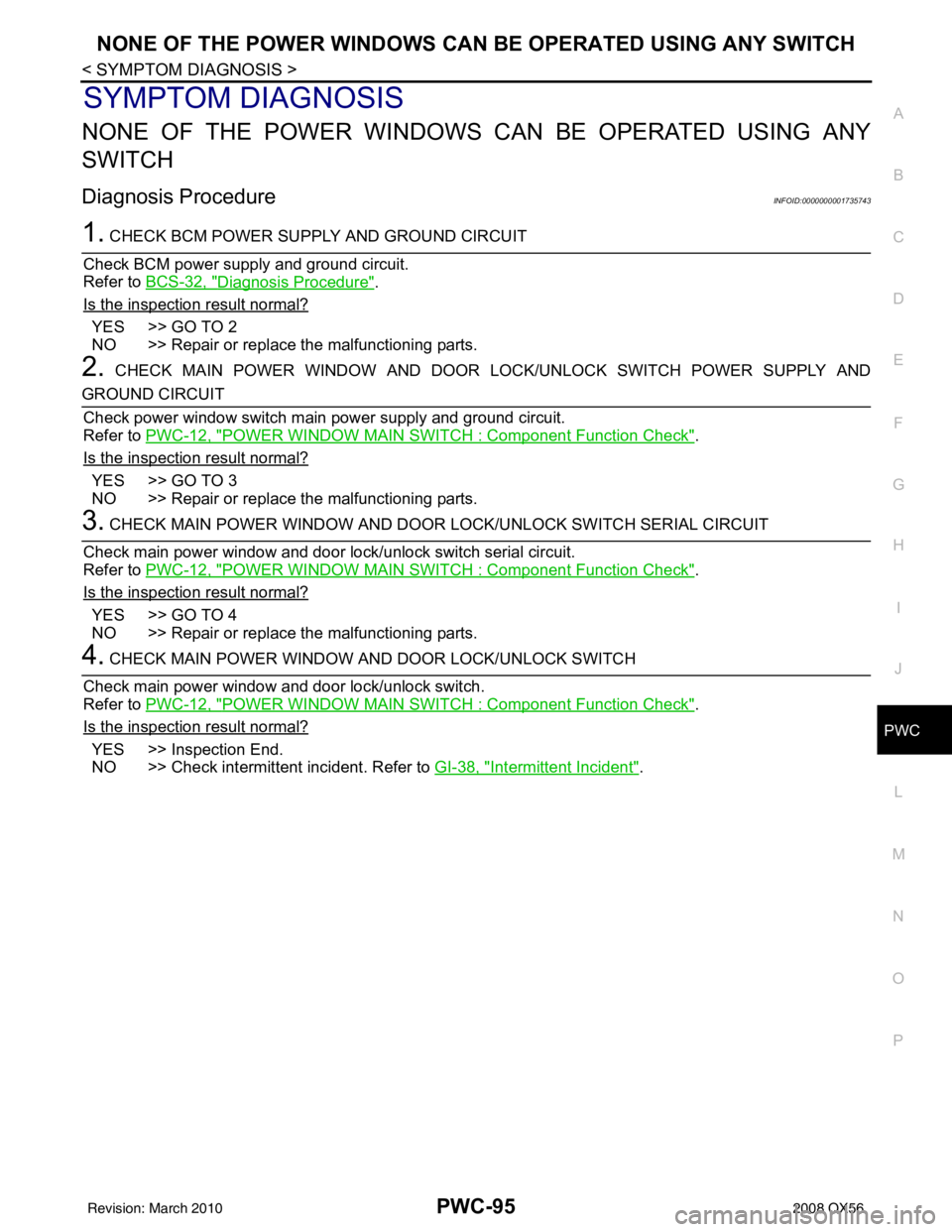
NONE OF THE POWER WINDOWS CAN BE OPERATED USING ANY
SWITCH
Diagnosis ProcedureINFOID:0000000001735743
1. CHECK BCM POWER SUPPLY AND GROUND CIRCUIT
Check BCM power supply and ground circuit.
Refer to BCS-32, "
Diagnosis Procedure".
Is the inspection result normal?
YES >> GO TO 2
NO >> Repair or replace the malfunctioning parts.
2. CHECK MAIN POWER WINDOW AND DOOR LOCK/UNLOCK SWITCH POWER SUPPLY AND
GROUND CIRCUIT
Check power window switch main power supply and ground circuit.
Refer to PWC-12, "
POWER WINDOW MAIN SWITCH : Component Function Check".
Is the inspection result normal?
YES >> GO TO 3
NO >> Repair or replace the malfunctioning parts.
3. CHECK MAIN POWER WINDOW AND DOOR LOCK/UNLOCK SWITCH SERIAL CIRCUIT
Check main power window and door lock/unlock switch serial circuit.
Refer to PWC-12, "
POWER WINDOW MAIN SWITCH : Component Function Check".
Is the inspection result normal?
YES >> GO TO 4
NO >> Repair or replace the malfunctioning parts.
4. CHECK MAIN POWER WINDOW A ND DOOR LOCK/UNLOCK SWITCH
Check main power window and door lock/unlock switch.
Refer to PWC-12, "
POWER WINDOW MAIN SWITCH : Component Function Check".
Is the inspection result normal?
YES >> Inspection End.
NO >> Check intermittent incident. Refer to GI-38, "
Intermittent Incident".
Revision: March 2010 2008 QX56
Page 2938 of 4083
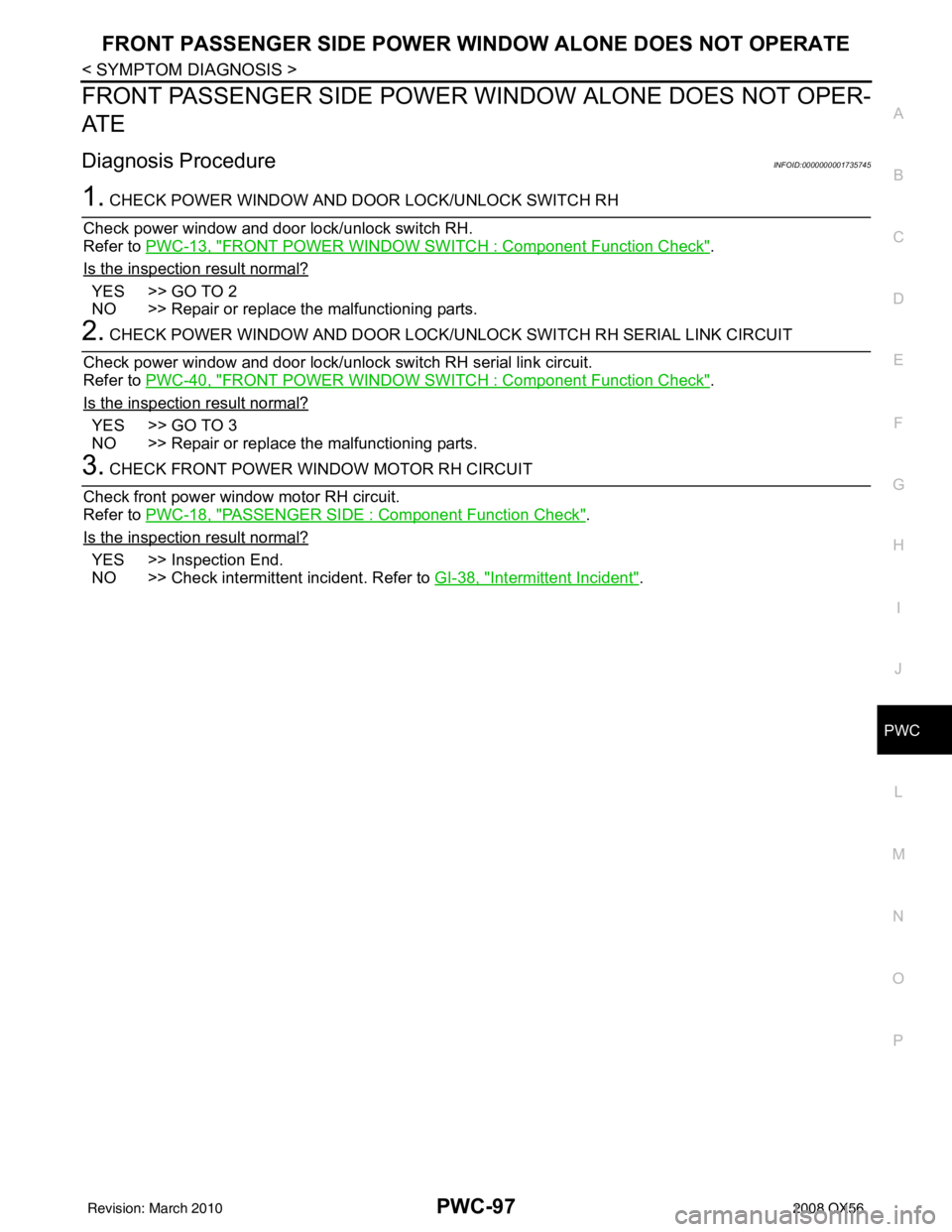
FRONT PASSENGER SIDE POWER WINDOW ALONE DOES NOT OPERATE
PWC-97
< SYMPTOM DIAGNOSIS >
C
D E
F
G H
I
J
L
M A
B
PWC
N
O P
FRONT PASSENGER SIDE POWER WINDOW ALONE DOES NOT OPER-
AT E
Diagnosis ProcedureINFOID:0000000001735745
1. CHECK POWER WINDOW AND DOOR LOCK/UNLOCK SWITCH RH
Check power window and door lock/unlock switch RH.
Refer to PWC-13, "
FRONT POWER WINDOW SWITCH : Component Function Check".
Is the inspection result normal?
YES >> GO TO 2
NO >> Repair or replace the malfunctioning parts.
2. CHECK POWER WINDOW AND DOOR LOCK/ UNLOCK SWITCH RH SERIAL LINK CIRCUIT
Check power window and door lock/unlock switch RH serial link circuit.
Refer to PWC-40, "
FRONT POWER WINDOW SWITCH : Component Function Check".
Is the inspection result normal?
YES >> GO TO 3
NO >> Repair or replace the malfunctioning parts.
3. CHECK FRONT POWER WINDOW MOTOR RH CIRCUIT
Check front power window motor RH circuit.
Refer to PWC-18, "
PASSENGER SIDE : Component Function Check".
Is the inspection result normal?
YES >> Inspection End.
NO >> Check intermittent incident. Refer to GI-38, "
Intermittent Incident".
Revision: March 2010 2008 QX56
Page 2950 of 4083
DOES NOT OPERATE BY KEY CYLINDER SWITCHPWC-109
< SYMPTOM DIAGNOSIS >
C
DE
F
G H
I
J
L
M A
B
PWC
N
O P
DOES NOT OPERATE BY KEY CYLINDER SWITCH
Diagnosis ProcedureINFOID:0000000001735753
1. CHECK FRONT DOOR LOCK ASSE MBLY LH (KEY CYLINDER SWITCH)
Check front door lock assembly LH (key cylinder switch).
Refer to PWC-36, "
Component Function Check".
Is the inspection result normal?
YES >> Inspection End.
NO >> Check intermittent incident. Refer to GI-38, "
Intermittent Incident".
Revision: March 2010 2008 QX56