2008 INFINITI QX56 Ignition switch removal
[x] Cancel search: Ignition switch removalPage 2584 of 4083
PRECAUTIONSLU-3
< PRECAUTION >
C
DE
F
G H
I
J
K L
M A
LU
NP
O
5. When the repair work is completed, return the ignition switch to the
″LOCK ″ position before connecting
the battery cables. (At this time, the steering lock mechanism will engage.)
6. Perform a self-diagnosis check of al l control units using CONSULT-III.
Precaution for Liquid GasketINFOID:0000000001538839
REMOVAL OF LIQUID GASKET SEALING
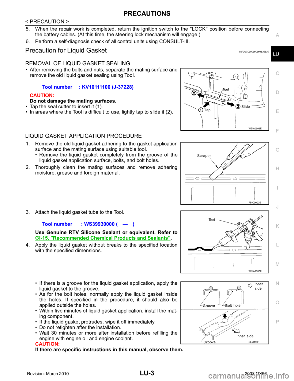
• After removing the bolts and nuts, separate the mating surface and
remove the old liquid gasket sealing using Tool.
CAUTION:
Do not damage the mating surfaces.
• Tap the seal cutter to insert it (1).
• In areas where the Tool is difficult to use, lightly tap to slide it (2).
LIQUID GASKET APPLICATION PROCEDURE
1. Remove the old liquid gasket adhering to the gasket application surface and the mating surface using suitable tool.
• Remove the liquid gasket completely from the groove of the
liquid gasket application surface, bolts, and bolt holes.
2. Thoroughly clean the mating surfaces and remove adhering moisture, grease and foreign material.
3. Attach the liquid gasket tube to the Tool. Use Genuine RTV Silicone Sealant or equivalent. Refer to
GI-15, "
Recommended Chemical Products and Sealants".
4. Apply the liquid gasket without breaks to the specified location with the specified dimensions.
• If there is a groove for the liquid gasket application, apply theliquid gasket to the groove.
• As for the bolt holes, normally apply the liquid gasket inside
the holes. If specified in the procedure, it should also be
applied outside the holes.
• Within five minutes of liquid gasket application, install the mat-
ing component.
• If the liquid gasket protrudes, wipe it off immediately.
• Do not retighten after the installation.
• Wait 30 minutes or more after installation before refilling the engine with engine oil and engine coolant.
CAUTION:
If there are specific instructions in this manual, observe them.
Tool number : KV10111100 (J-37228)
WBIA0566E
PBIC0003E
Tool number : WS39930000 ( — )
WBIA0567E
SEM159F
Revision: March 2010
2008 QX56
Page 2600 of 4083

MA-2
< PREPARATION >
PRECAUTIONS
PREPARATION
PRECAUTIONS
Precaution for Supplemental Restraint System (SRS) "AIR BAG" and "SEAT BELT
PRE-TENSIONER"
INFOID:0000000006054111
The Supplemental Restraint System such as “A IR BAG” and “SEAT BELT PRE-TENSIONER”, used along
with a front seat belt, helps to reduce the risk or severity of injury to the driver and front passenger for certain
types of collision. This system includes seat belt switch inputs and dual stage front air bag modules. The SRS
system uses the seat belt switches to determine the front air bag deployment, and may only deploy one front
air bag, depending on the severity of a collision and w hether the front occupants are belted or unbelted.
Information necessary to service the system safely is included in the SR and SB section of this Service Man-
ual.
WARNING:
• To avoid rendering the SRS inopera tive, which could increase the risk of personal injury or death in
the event of a collision which would result in air bag inflation, all maintenance must be performed by
an authorized NISSAN/INFINITI dealer.
• Improper maintenance, including in correct removal and installation of the SRS, can lead to personal
injury caused by unintent ional activation of the system. For re moval of Spiral Cable and Air Bag
Module, see the SR section.
• Do not use electrical test equipmen t on any circuit related to the SRS unless instructed to in this
Service Manual. SRS wiring harn esses can be identified by yellow and/or orange harnesses or har-
ness connectors.
PRECAUTIONS WHEN USING POWER TOOLS (AIR OR ELECTRIC) AND HAMMERS
WARNING:
• When working near the Airbag Diagnosis Sensor Unit or other Airbag System sensors with the Igni-
tion ON or engine running, DO NOT use air or electri c power tools or strike near the sensor(s) with a
hammer. Heavy vibration could activate the sensor( s) and deploy the air bag(s), possibly causing
serious injury.
• When using air or electric power tools or hammers , always switch the Ignition OFF, disconnect the
battery, and wait at least 3 minu tes before performing any service.
Precaution Necessary for Steering W heel Rotation After Battery Disconnect
INFOID:0000000004900832
NOTE:
• This Procedure is applied only to models with Intelligent Key system and NATS (NISSAN ANTI-THEFT SYS-
TEM).
• Remove and install all control units after disconnecting both battery cables with the ignition knob in the
″LOCK ″ position.
• Always use CONSULT-III to perform self-diagnosis as a part of each function inspection after finishing work.
If DTC is detected, perform trouble diagnosis according to self-diagnostic results.
For models equipped with the Intelligent Key system and NATS, an electrically controlled steering lock mech-
anism is adopted on the key cylinder.
For this reason, if the battery is disconnected or if the battery is discharged, the steering wheel will lock and
steering wheel rotation will become impossible.
If steering wheel rotation is required when battery pow er is interrupted, follow the procedure below before
starting the repair operation.
OPERATION PROCEDURE
1. Connect both battery cables. NOTE:
Supply power using jumper cables if battery is discharged.
2. Use the Intelligent Key or mechanical key to turn the ignition switch to the ″ACC ″ position. At this time, the
steering lock will be released.
3. Disconnect both battery cables. The steering lock will remain released and the steering wheel can be rotated.
4. Perform the necessary repair operation.
Revision: March 2010 2008 QX56
Page 2612 of 4083
MA-14
< ON-VEHICLE MAINTENANCE >
ENGINE MAINTENANCE
ENGINE MAINTENANCE
Checking Drive BeltsINFOID:0000000001606170
WARNING:
Be sure to perform when the engine is stopped.
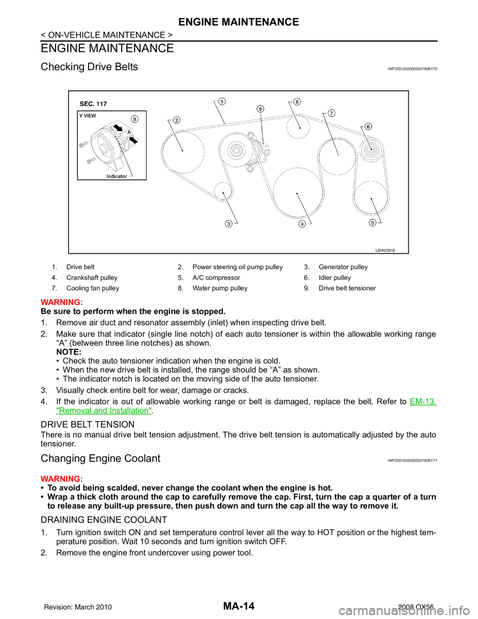
1. Remove air duct and resonator assembly (inlet) when inspecting drive belt.
2. Make sure that indicator (single line notch) of each auto tensioner is within the allowable working range“A” (between three line notches) as shown.
NOTE:
• Check the auto tensioner indication when the engine is cold.
• When the new drive belt is installed, the range should be “A” as shown.
• The indicator notch is located on the moving side of the auto tensioner.
3. Visually check entire belt for wear, damage or cracks.
4. If the indicator is out of allowable working range or belt is damaged, replace the belt. Refer to EM-13,
"Removal and Installation".
DRIVE BELT TENSION
There is no manual drive belt tension adjustment. The driv e belt tension is automatically adjusted by the auto
tensioner.
Changing Engine CoolantINFOID:0000000001606171
WARNING:
• To avoid being scalded, never change the coolant when the engine is hot.
• Wrap a thick cloth around the cap to carefully remove the cap. First, turn the cap a quarter of a turn
to release any built-up pressure, th en push down and turn the cap all the way to remove it.
DRAINING ENGINE COOLANT
1. Turn ignition switch ON and set temperature control lever all the way to HOT position or the highest tem-
perature position. Wait 10 seconds and turn ignition switch OFF.
2. Remove the engine front undercover using power tool.
1. Drive belt 2. Power steering oil pump pulley 3. Generator pulley
4. Crankshaft pulley 5. A/C compressor6. Idler pulley
7. Cooling fan pulley 8. Water pump pulley 9. Drive belt tensioner
LBIA0391E
Revision: March 2010 2008 QX56
Page 2640 of 4083

MIR-8
< PRECAUTION >
PRECAUTIONS
PRECAUTION
PRECAUTIONS
Precaution for Supplemental Restraint System (SRS) "AIR BAG" and "SEAT BELT
PRE-TENSIONER"
INFOID:0000000004873066
The Supplemental Restraint System such as “A IR BAG” and “SEAT BELT PRE-TENSIONER”, used along
with a front seat belt, helps to reduce the risk or severity of injury to the driver and front passenger for certain
types of collision. This system includes seat belt switch inputs and dual stage front air bag modules. The SRS
system uses the seat belt switches to determine the front air bag deployment, and may only deploy one front
air bag, depending on the severity of a collision and w hether the front occupants are belted or unbelted.
Information necessary to service the system safely is included in the SR and SB section of this Service Man-
ual.
WARNING:
• To avoid rendering the SRS inopera tive, which could increase the risk of personal injury or death in
the event of a collision which would result in air bag inflation, all maintenance must be performed by
an authorized NISSAN/INFINITI dealer.
• Improper maintenance, including in correct removal and installation of the SRS, can lead to personal
injury caused by unintent ional activation of the system. For re moval of Spiral Cable and Air Bag
Module, see the SR section.
• Do not use electrical test equipmen t on any circuit related to the SRS unless instructed to in this
Service Manual. SRS wiring harn esses can be identified by yellow and/or orange harnesses or har-
ness connectors.
PRECAUTIONS WHEN USING POWER TOOLS (AIR OR ELECTRIC) AND HAMMERS
WARNING:
• When working near the Airbag Diagnosis Sensor Unit or other Airbag System sensors with the Igni-
tion ON or engine running, DO NOT use air or electri c power tools or strike near the sensor(s) with a
hammer. Heavy vibration could activate the sensor( s) and deploy the air bag(s), possibly causing
serious injury.
• When using air or electric power tools or hammers , always switch the Ignition OFF, disconnect the
battery, and wait at least 3 minu tes before performing any service.
Precaution Necessary for Steering W heel Rotation After Battery Disconnect
INFOID:0000000004873067
NOTE:
• This Procedure is applied only to models with Intelligent Key system and NATS (NISSAN ANTI-THEFT SYS-
TEM).
• Remove and install all control units after disconnecting both battery cables with the ignition knob in the
″LOCK ″ position.
• Always use CONSULT-III to perform self-diagnosis as a part of each function inspection after finishing work.
If DTC is detected, perform trouble diagnosis according to self-diagnostic results.
For models equipped with the Intelligent Key system and NATS, an electrically controlled steering lock mech-
anism is adopted on the key cylinder.
For this reason, if the battery is disconnected or if the battery is discharged, the steering wheel will lock and
steering wheel rotation will become impossible.
If steering wheel rotation is required when battery pow er is interrupted, follow the procedure below before
starting the repair operation.
OPERATION PROCEDURE
1. Connect both battery cables. NOTE:
Supply power using jumper cables if battery is discharged.
2. Use the Intelligent Key or mechanical key to turn the ignition switch to the ″ACC ″ position. At this time, the
steering lock will be released.
3. Disconnect both battery cables. The steering lock will remain released and the steering wheel can be rotated.
4. Perform the necessary repair operation.
Revision: March 2010 2008 QX56
Page 2669 of 4083
MWI-24
< FUNCTION DIAGNOSIS >
DIAGNOSIS SYSTEM (METER)
DIAGNOSIS SYSTEM (METER)
Diagnosis DescriptionINFOID:0000000001691283
SELF-DIAGNOSIS MODE
The following items can be checked during Combination Meter Self-Diagnosis Mode.
• Gauge sweep and present gauge values.
• Illuminates all odometer/trip meters and A/T indicator segments.
• Illuminates all micro controlled lamps/LEDs regardless of switch position.
• Displays estimated present battery voltage.
• Displays seat belt buckle switch LH status.
OPERATION PROCEDURE
NOTE:
• Once entered, combination meter self-diagnosis mode will function with the ignition switch in ON or START.
Combination meter self-diagnosis mode will exit upon turning the ignition switch to OFF or ACC.
• If the diagnosis function is activated with trip A displa yed, the mileage on trip A is reset to 0000.0. (Trip B
operates the same way.)
To initiate combination meter self-diagnosis mode, refer to the following procedure.
1. Turn the ignition switch ON, while pressing the odometer/trip meter switch for 5 - 8 \
seconds. When the diagnosis function is activated, the odometer/trip meter will display tESt.
NOTE:
Check combination meter power supply and ground circuit when self-diagnosis mode of combination meter
does not start. Refer to MWI-30, "
COMBINATION METER : Diagnosis Procedure". Replace combination
meter if normal. Refer to MWI-76, "
Removal and Installation".
COMBINATION METER SELF-DIAGNOSIS MODE FUNCTIONS
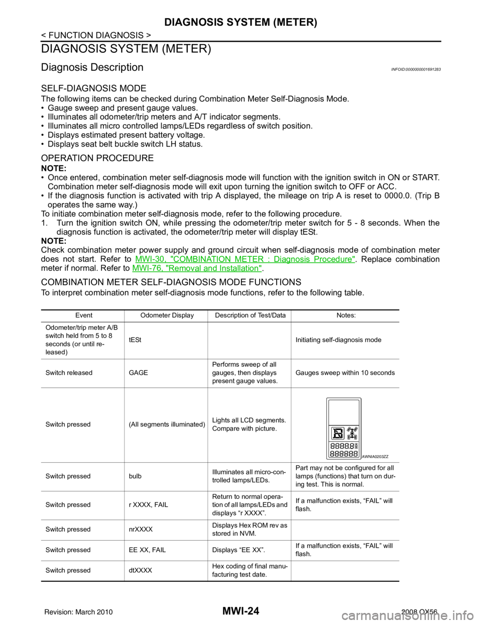
To interpret combination meter self-diagnosis mode functions, refer to the following table.
EventOdometer Display Description of Test/Data Notes:
Odometer/trip meter A/B
switch held from 5 to 8
seconds (or until re-
leased) tESt
Initiating self-diagnosis mode
Switch released GAGE Performs sweep of all
gauges, then displays
present gauge values.Gauges sweep within 10 seconds
Switch pressed (All segments illuminated) Lights all LCD segments.
Compare with picture.
Switch pressed bulbIlluminates all micro-con-
trolled lamps/LEDs. Part may not be configured for all
lamps (functions) th
at turn on dur-
ing test. This is normal.
Switch pressed r XXXX, FAIL Return to normal opera-
tion of all lamps/LEDs and
displays “r XXXX”.If a malfunction exists, “FAIL” will
flash.
Switch pressed nrXXXX Displays Hex ROM rev as
stored in NVM.
Switch pressed EE XX, FAIL Displays “EE XX”.If a malfunction exists, “FAIL” will
flash.
Switch pressed dtXXXX Hex coding of final manu-
facturing test date.
AWNIA0203ZZ
Revision: March 2010
2008 QX56
Page 2678 of 4083
MWI
FUEL LEVEL SENSOR SIGNAL CIRCUITMWI-33
< COMPONENT DIAGNOSIS >
C
DE
F
G H
I
J
K L
M B A
O P
FUEL LEVEL SENSOR SIGNAL CIRCUIT
DescriptionINFOID:0000000001691293
The fuel level sensor unit and fuel pump detects the approx imate fuel level in the fuel tank and transmits the
fuel level signal to the combination meter.
Component Function CheckINFOID:0000000001691294
1.COMBINATION METER INPUT SIGNAL
1. Select “METER/M&A” on CONSULT-III.
2. Using “FUEL METER” of “DATA MONITOR”, comp are the value of DATA MONITOR with fuel gauge
pointer of combination meter.
Does the data monitor value approximately match the fuel gauge indication?
YES >> Inspection End.
NO >> Replace combination meter. Refer to MWI-76, "
Removal and Installation".
Diagnosis ProcedureINFOID:0000000001691295
1.CHECK HARNESS CONNECTOR
1. Turn ignition switch OFF.
2. Check combination meter and fuel level sensor unit terminals (meter-side and harness-side) for poor con- nection.
Is the inspection result normal?
YES >> GO TO 2
NO >> Repair or replace terminals or connectors.
2.CHECK FUEL LEVEL SENSOR UNIT CIRCUIT
1. Disconnect combination meter connector and fuel level sensor unit connector.
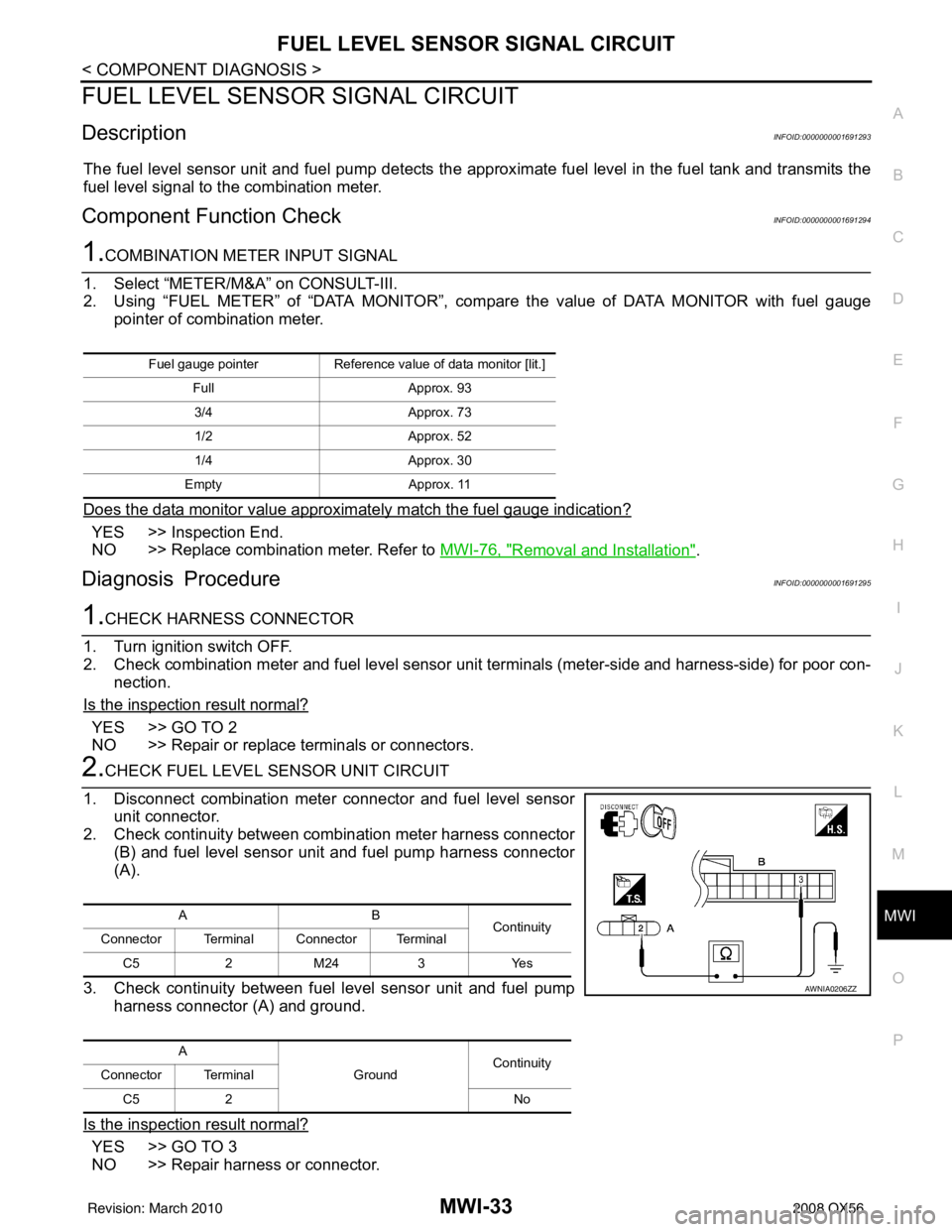
2. Check continuity between combination meter harness connector
(B) and fuel level sensor unit and fuel pump harness connector
(A).
3. Check continuity between fuel level sensor unit and fuel pump harness connector (A) and ground.
Is the inspection result normal?
YES >> GO TO 3
NO >> Repair harness or connector.
Fuel gauge pointer Reference value of data monitor [lit.]
Full Approx. 93
3/4 Approx. 73
1/2 Approx. 52
1/4 Approx. 30
Empty Approx. 11
AB
Continuity
Connector Terminal Connector Terminal
C5 2 M24 3 Yes
A GroundContinuity
Connector Terminal
C5 2 No
AWNIA0206ZZ
Revision: March 2010 2008 QX56
Page 2713 of 4083
MWI-68
< SYMPTOM DIAGNOSIS >
THE OIL PRESSURE WARNING LAMP DOES NOT TURN ON
THE OIL PRESSURE WARNING LAMP DOES NOT TURN ON
DescriptionINFOID:0000000001691329
The oil pressure warning lamp stays off when the ignition switch is turned ON.
Diagnosis ProcedureINFOID:0000000001691330
1.CHECK OIL PRESSURE WARNING LAMP
Perform IPDM E/R auto active test. Refer to PCS-12, "
Diagnosis Description".
Is oil pressure warning lamp illuminated?
YES >> GO TO 2
NO >> Replace combination meter. Refer to MWI-76, "
Removal and Installation".
2.CHECK OIL PRESSURE SWITCH SIGNAL CIRCUIT
Check the oil pressure switch signal circuit. Refer to MWI-35, "
Diagnosis Procedure".
Is the inspection result normal?
YES >> GO TO 3
NO >> Repair harness or connector.
3.CHECK OIL PRESSURE SWITCH UNIT
Perform a unit check for the oil pressure switch. Refer to MWI-35, "
Component Inspection".
Is the inspection result normal?
YES >> Replace IPDM E/R. Refer to PCS-34, "Removal and Installation of IPDM E/R".
NO >> Replace oil pressure switch.
Revision: March 2010 2008 QX56
Page 2714 of 4083
MWI
THE OIL PRESSURE WARNING LAMP DOES NOT TURN OFFMWI-69
< SYMPTOM DIAGNOSIS >
C
DE
F
G H
I
J
K L
M B A
O P
THE OIL PRESSURE WARNING LAMP DOES NOT TURN OFF
DescriptionINFOID:0000000001691331
The oil pressure warning lamp remains illuminated while the engine is running (normal oil pressure).
Diagnosis ProcedureINFOID:0000000001691332
1.CHECK OIL PRESSURE WARNING LAMP
Perform IPDM E/R auto active test. Refer to PCS-12, "
Diagnosis Description".
Is oil pressure warning lamp illuminated?
YES >> GO TO 2
NO >> Replace combination meter. Refer to MWI-76, "
Removal and Installation".
2.CHECK IPDM E/R OUTPUT VOLTAGE
1. Turn ignition switch OFF.
2. Disconnect the oil pressure switch connector.
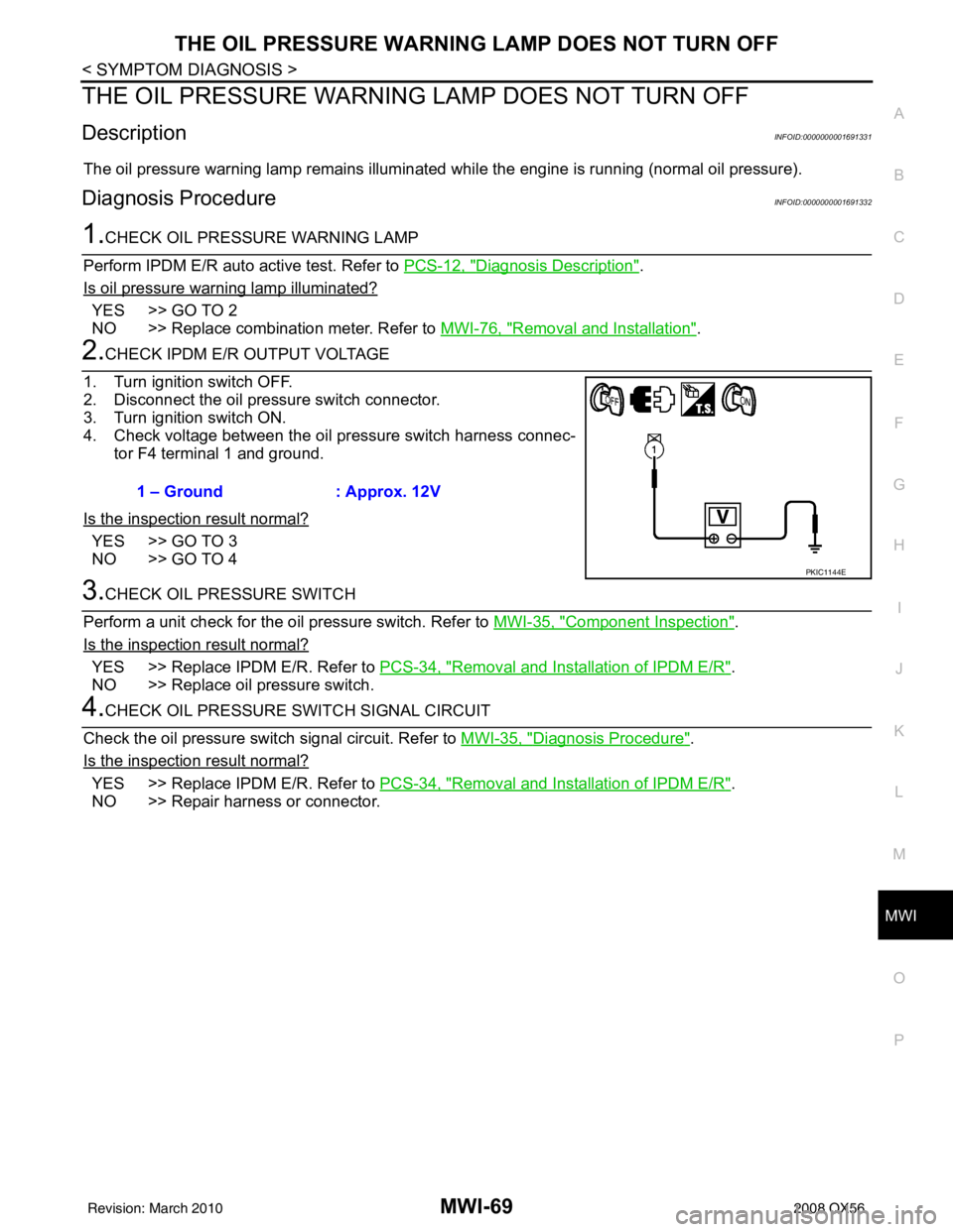
3. Turn ignition switch ON.
4. Check voltage between the oil pressure switch harness connec- tor F4 terminal 1 and ground.
Is the inspection result normal?
YES >> GO TO 3
NO >> GO TO 4
3.CHECK OIL PRESSURE SWITCH
Perform a unit check for the oil pressure switch. Refer to MWI-35, "
Component Inspection".
Is the inspection result normal?
YES >> Replace IPDM E/R. Refer to PCS-34, "Removal and Installation of IPDM E/R".
NO >> Replace oil pressure switch.
4.CHECK OIL PRESSURE SWITCH SIGNAL CIRCUIT
Check the oil pressure switch signal circuit. Refer to MWI-35, "
Diagnosis Procedure".
Is the inspection result normal?
YES >> Replace IPDM E/R. Refer to PCS-34, "Removal and Installation of IPDM E/R".
NO >> Repair harness or connector. 1 – Ground
: Approx. 12V
PKIC1144E
Revision: March 2010 2008 QX56