2008 INFINITI QX56 glove box
[x] Cancel search: glove boxPage 2620 of 4083
MA-22
< ON-VEHICLE MAINTENANCE >
CHASSIS AND BODY MAINTENANCE
CHASSIS AND BODY MAINTENANCE
Changing In-cabin MicrofilterINFOID:0000000001606179
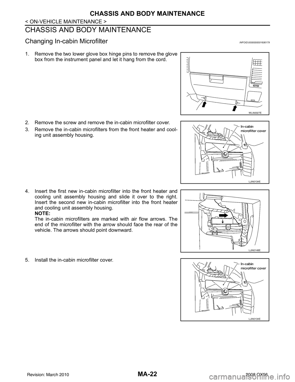
1. Remove the two lower glove box hinge pins to remove the glovebox from the instrument panel and let it hang from the cord.
2. Remove the screw and remove the in-cabin microfilter cover.
3. Remove the in-cabin microfilters from the front heater and cool- ing unit assembly housing.
4. Insert the first new in-cabin micr ofilter into the front heater and
cooling unit assembly housing and slide it over to the right.
Insert the second new in-cabin mi crofilter into the front heater
and cooling unit assembly housing.
NOTE:
The in-cabin microfilters are marked with air flow arrows. The
end of the microfilter with the arro w should face the rear of the
vehicle. The arrows should point downward.
5. Install the in-cabin microfilter cover.
WLIA0027E
LJIA0134E
LJIA0148E
LJIA0134E
Revision: March 2010 2008 QX56
Page 2621 of 4083
CHASSIS AND BODY MAINTENANCEMA-23
< ON-VEHICLE MAINTENANCE >
C
DE
F
G H
I
J
K L
M B
MA
N
O A
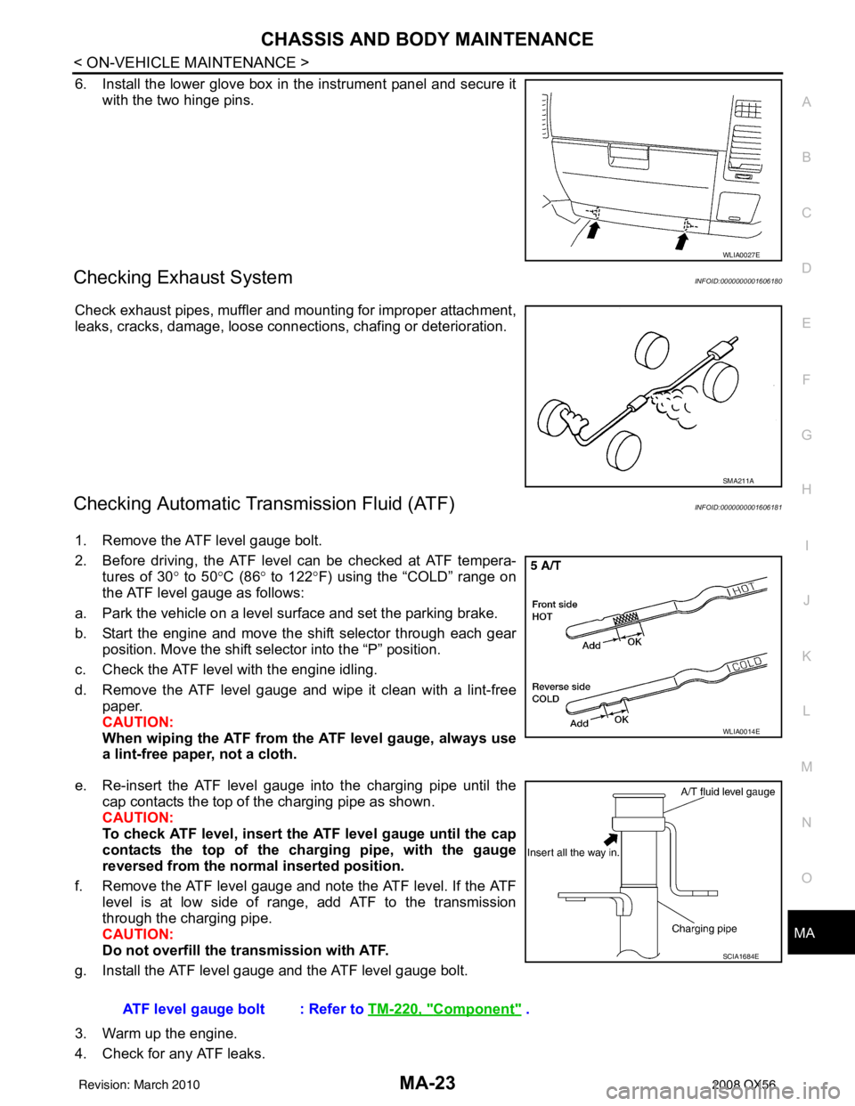
6. Install the lower glove box in the instrument panel and secure it
with the two hinge pins.
Checking Exhaust SystemINFOID:0000000001606180
Check exhaust pipes, muffler and mounting for improper attachment,
leaks, cracks, damage, loose connec tions, chafing or deterioration.
Checking Automatic Transmission Fluid (ATF)INFOID:0000000001606181
1. Remove the ATF level gauge bolt.
2. Before driving, the ATF level can be checked at ATF tempera-
tures of 30 ° to 50 °C (86° to 122° F) using the “COLD” range on
the ATF level gauge as follows:
a. Park the vehicle on a level surface and set the parking brake.
b. Start the engine and move the shift selector through each gear position. Move the shift selector into the “P” position.
c. Check the ATF level with the engine idling.
d. Remove the ATF level gauge and wipe it clean with a lint-free paper.
CAUTION:
When wiping the ATF from the ATF level gauge, always use
a lint-free paper, not a cloth.
e. Re-insert the ATF level gauge into the charging pipe until the cap contacts the top of the charging pipe as shown.
CAUTION:
To check ATF level, insert the ATF level gauge until the cap
contacts the top of the charging pipe, with the gauge
reversed from the normal inserted position.
f. Remove the ATF level gauge and note the ATF level. If the ATF level is at low side of range, add ATF to the transmission
through the charging pipe.
CAUTION:
Do not overfill the tr ansmission with ATF.
g. Install the ATF level gauge and the ATF level gauge bolt.
3. Warm up the engine.
4. Check for any ATF leaks.
WLIA0027E
SMA211A
WLIA0014E
ATF level gauge bolt : Refer to TM-220, "Component" .
SCIA1684E
Revision: March 2010 2008 QX56
Page 2810 of 4083

PG
HARNESSPG-43
< COMPONENT DIAGNOSIS >
C
DE
F
G H
I
J
K L
B A
O P
N
D4 M56 W/16 : To M201
D4 M203 W/12 : A/T shift selector
A3 M57 — : Body ground D5 M205 W/32 : DVD player
F2 M58 B/6 : Intake door motor D5 M207 BR/20 : Console power socket
F3 M59 BR/2 : Glove box lamp C4 M208 BR/20 : To M69
G3 M60 W/6 : Fuse block (J/B) C5 M209 W/2: Inside key antenna 2 (rear of center
console)
C3 M61 — : Body ground C4 M210 GR/2: Inside key antenna 3 (front of center
console)
F4 M62 B/2 : Front blower motor C4 M212 W/6 : Rear heated seat switch LH
D4 M63 BR/20 : To M251 C4 M213 BR/6 : Rear heated seat switch RH
D4 M64 BR/24 : To M202 Console switch sub-harness
F2 M65 W/4 : To M301 D4 M251 BR/20 : To M63
G3 M66 BR/1 : To E33 D4 M252 BR/6 : Front heated seat switch RH
C3 M69 BR/20 : To M208 C4 M253 GR/6 : VDC OFF switch
A2 M70 W/40 : Intelligent key unit C3 M255 W/6 : Front heated seat switch LH
A2 M71 L/4 : Heated steering relay C4 M256 B/2 : A/T shift selector
D3 M73 BR/6 : Back-up lamp relay C4 M260 W/6 : Heated steering wheel switch
G3 M74 BR/24 : To D102 Optical sensor sub-harness
G3 M75 W/10 : To D101 F1 M301 W/4 : To M65
A3 M76 W/6 : Electric brake (pre-wiring) D1 M302 B/4 : Optical sensor
E2 M77 Y/4 : Front passenger air bag module
(service replacement) Antenna amp. sub-harness
G3 M78 BR/2 : To M550 D3 M550 BR/2 : To M78
E2 M79 — : Body ground D3 M551 BR/3 : To M601
C1 M80 B/2 : Resistor D3 M601 GR/3 : To M551
E3 M81 GR/10 : Shift lock control unit D3 M602 W/2 : Antenna amp.
A3 M82 GR/2 : Circuit breaker-2
Revision: March 2010 2008 QX56
Page 3218 of 4083
![INFINITI QX56 2008 Factory Service Manual SEC-10
< FUNCTION DIAGNOSIS >[WITH INTELLIGENT KEY SYSTEM]
INTELLIGENT KEY SYSTEM/ENGINE START FUNCTION
• Intelligent Key has 2 IDs (for Intelligent Key and for
NATS). It can perform the door lock/ INFINITI QX56 2008 Factory Service Manual SEC-10
< FUNCTION DIAGNOSIS >[WITH INTELLIGENT KEY SYSTEM]
INTELLIGENT KEY SYSTEM/ENGINE START FUNCTION
• Intelligent Key has 2 IDs (for Intelligent Key and for
NATS). It can perform the door lock/](/manual-img/42/57030/w960_57030-3217.png)
SEC-10
< FUNCTION DIAGNOSIS >[WITH INTELLIGENT KEY SYSTEM]
INTELLIGENT KEY SYSTEM/ENGINE START FUNCTION
• Intelligent Key has 2 IDs (for Intelligent Key and for
NATS). It can perform the door lock/unlock operation and
the engine start operation when the registered Intelligent Key is carried.
• When the Intelligent Key battery is discharged, it can be used as emergency back-up by inserting the
mechanical key set in the Intelligent Key to the ignition key cylinder. At that time, perform the NATS ID verifi-
cation. If it is used when the Intelligent Key is carried, perform the Intelligent Key ID verification.
• If the ID is successfully verified, and when the igniti on knob switch is pressed, steering lock will be released
and initiating the engine will be possible.
• The door lock/unlock operation can be performed when the Intelligent Key battery is discharged, by operat-
ing the driver door key cylinder using the mechanical key set in the Intelligent Key.
• Up to 4 Intelligent Keys can be registered (including the standard Intelligent Key) on request from the owner. NOTE:
• Refer to DLK-17, "
INTELLIGENT KEY : System Description" for any functions other than engine start func-
tion of Intelligent Key system.
PRECAUTIONS FOR INTELLIGENT KEY SYSTEM
• For vehicles equipped with the Intelligent Key system , the transponder [the chip for NATS ID verifi-
cation] is integrated into the Inte lligent Key. Therefore, the Intellig ent Key alone is capable of provid-
ing security clearance for the engine to start. Also, when the mechanical key alone is inserted into
the key cylinder, performs the NATS ID verification to allow the engine to start. For vehicles without
Intelligent Key system, the transponder is integrated into the mechanical key which must be inserted
into the key cylinder to perform the NATS ID verification to allow the engine to start.
OPERATION WHEN INTELLIGENT KEY IS CARRIED
1. When the ignition knob switch is ON, the Intelligent Key unit transmits the request signal to the Intelligent
Key.
2. The Intelligent Key receives the request signal and transmits the Intelligent Key ID signal to the Intelligent Key unit.
3. The Intelligent Key unit receives the Intelligent Key ID signal and verifies it with the registered ID.
4. Intelligent Key unit transmits the steering lock/unlock signal to steering lock solenoid if the verification results are OK. For detail of key warning message operation, refer to DLK-34, "
System Description".
5. Release of the steering lock.
6. BCM transmits the starter request signal via CAN communication to IPDM E/R and turns the starter relay in IPDM E/R ON if BCM judges that the engine start condition is satisfied.
7. IPDM E/R turns the starter control relay ON when receiving the starter request signal.
8. When shift position is in P or N position, battery power is supplied through the starter relay and operate the starter motor and to start the cranking.
CAUTION:
If a malfunction is detected in the Intelligent Key system, the “KEY” warning message will be dis-
played in the combination meter. At th at time, the engine cannot be started.
OPERATION RANGE
Engine can be started when Intelligent Key is inside the vehicle. However, sometimes engine might not start
when Intelligent Key is on instrument panel or in glove box.
OPERATION WHEN MECHANICAL KEY IS USED
When the Intelligent Key battery is discharged, performs the NATS ID verification between the integrated tran-
sponder and BCM by inserting the mechanical key into the key cylinder, and then the engine can be started.
For details relating to starting the engine using mechanical key, refer to SEC-13, "
System Description".
STEERING LOCK OPERATION
Steering is locked by steering lock solenoid when ignition switch is in the LOCK position (the ignition knob is
released) and key switch is OFF (key is removed from ignition key cylinder).
Revision: March 2010 2008 QX56
Page 3386 of 4083
SR-10
< ON-VEHICLE REPAIR >
FRONT PASSENGER AIR BAG MODULE
FRONT PASSENGER AIR BAG MODULE
Removal and InstallationINFOID:0000000001602203
The passenger air bag module originally installed in the vehicle uses direct-connect style harness connectors.
Service replacement passenger air bag modules use tab-locking style harness connectors. If the passenger
air bag module is replaced or if the direct-connect harness connectors are damaged, the vehicle wiring har-
ness must be modified to allow connection of the se rvice replacement passenger air bag module. Refer to
"Service Replacement Passenger Air Bag Module" within the INSTALLATION procedure in this section for wir-
ing harness modifiation procedure.
REMOVAL
CAUTION:
• Do not attempt to repair or replace damaged di rect-connect front passenger air bag module connec-
tors. If a direct-connect harness connector is damaged, the front passenger air bag must be
replaced and the wiri ng harness modified.
• Before servicing SRS, turn the ignition switch off, disco nnect both battery cables and wait at least
three minutes.
• Always work from the side of or under front passenger air bag module.
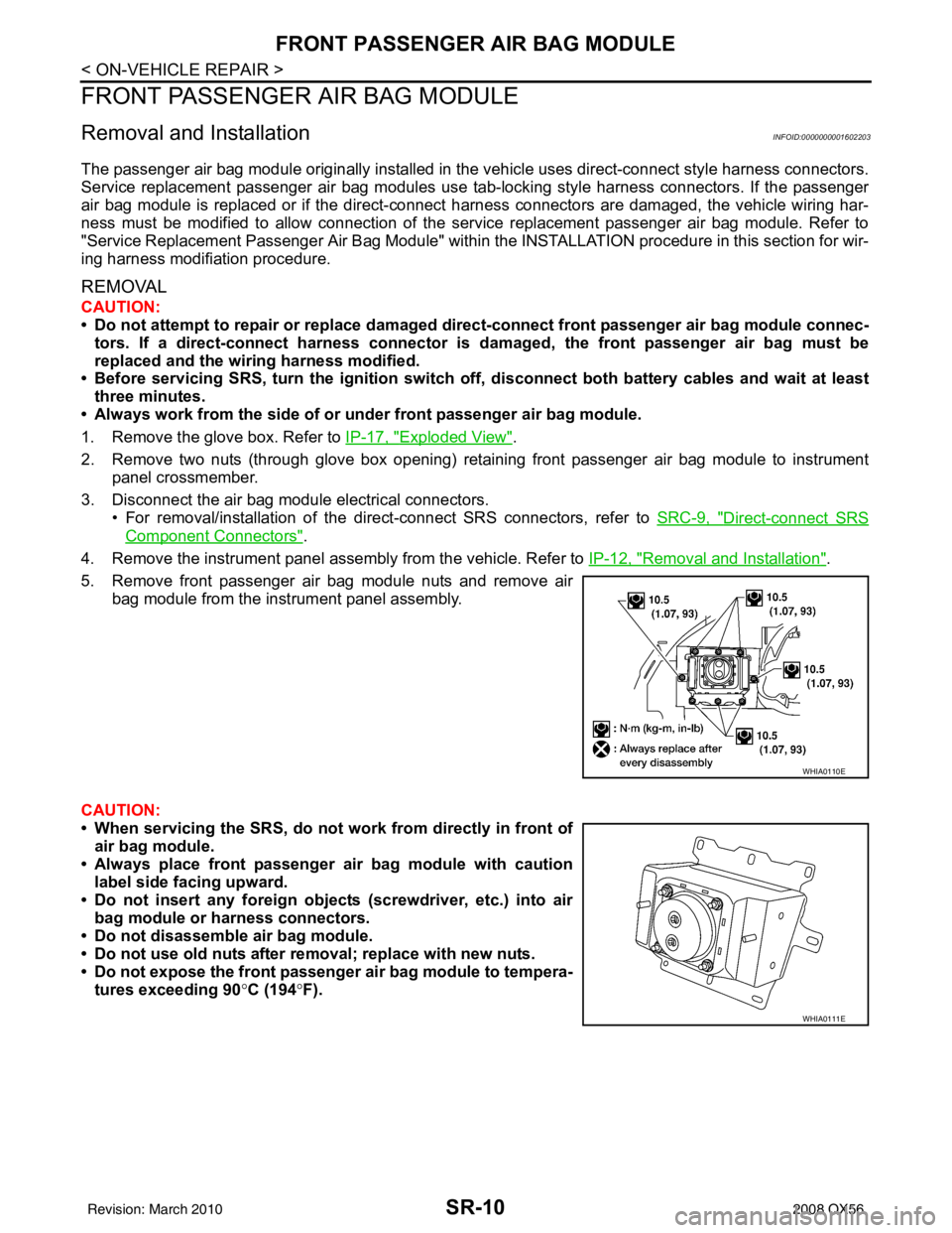
1. Remove the glove box. Refer to IP-17, "
Exploded View".
2. Remove two nuts (through glove box opening) retaining front passenger air bag module to instrument panel crossmember.
3. Disconnect the air bag module electrical connectors. • For removal/installation of the direct-connect SRS connectors, refer to SRC-9, "
Direct-connect SRS
Component Connectors".
4. Remove the instrument panel assembly from the vehicle. Refer to IP-12, "
Removal and Installation".
5. Remove front passenger air bag module nuts and remove air bag module from the instrument panel assembly.
CAUTION:
• When servicing the SRS, do not work from directly in front of
air bag module.
• Always place front passenger air bag module with caution label side facing upward.
• Do not insert any foreign object s (screwdriver, etc.) into air
bag module or harness connectors.
• Do not disassemble air bag module.
• Do not use old nuts after removal; replace with new nuts.
• Do not expose the front passenger air bag module to tempera- tures exceeding 90 °C (194 °F).
WHIA0110E
WHIA0111E
Revision: March 2010 2008 QX56
Page 3846 of 4083
VTL-6
< ON-VEHICLE MAINTENANCE >
IN-CABIN MICROFILTER
ON-VEHICLE MAINTENANCE
IN-CABIN MICROFILTER
Removal and InstallationINFOID:0000000001516602
REPLACEMENT PROCEDURE
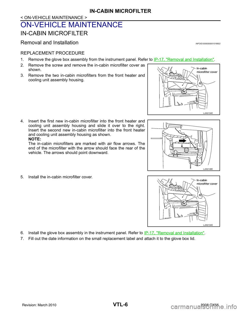
1. Remove the glove box assembly from the instrument panel. Refer to IP-17, "Removal and Installation".
2. Remove the screw and remove the in-cabin microfilter cover as shown.
3. Remove the two in-cabin microf ilters from the front heater and
cooling unit assembly housing.
4. Insert the first new in-cabin micr ofilter into the front heater and
cooling unit assembly housing and slide it over to the right.
Insert the second new in-cabin mi crofilter into the front heater
and cooling unit assembly housing as shown.
NOTE:
The in-cabin microfilters are marked with air flow arrows. The
end of the microfilter with the arro w should face the rear of the
vehicle. The arrows should point downward.
5. Install the in-cabin microfilter cover.
6. Install the glove box assembly in the instrument panel. Refer to IP-17, "
Removal and Installation".
7. Fill out the date information on the small replac ement label and attach it to the glove box lid.
LJIA0134E
LJIA0148E
LJIA0134E
Revision: March 2010 2008 QX56
Page 3852 of 4083
VTL-12
< ON-VEHICLE REPAIR >
BLOWER MOTOR
BLOWER MOTOR
ComponentINFOID:0000000001516607
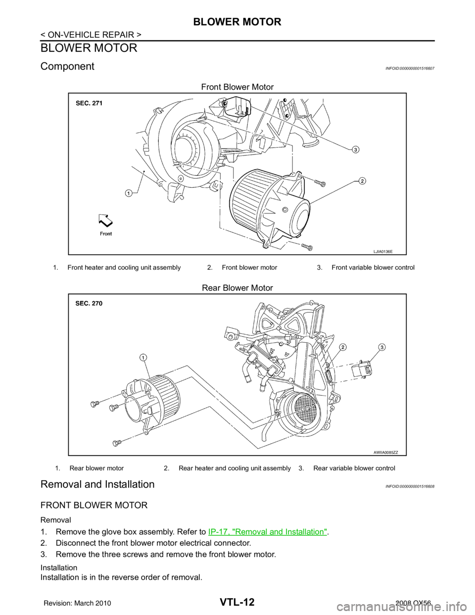
Front Blower MotorRear Blower Motor
Removal and InstallationINFOID:0000000001516608
FRONT BLOWER MOTOR
Removal
1. Remove the glove box assembly. Refer to IP-17, "Removal and Installation".
2. Disconnect the front blower motor electrical connector.
3. Remove the three screws and remove the front blower motor.
Installation
Installation is in the reverse order of removal.
LJIA0136E
1. Front heater and cooling unit assembly 2. Front blower motor 3. Front variable blower control
AWIIA0085ZZ
1. Rear blower motor2. Rear heater and cooling unit assembly 3. Rear variable blower control
Revision: March 2010 2008 QX56
Page 3854 of 4083
VTL-14
< ON-VEHICLE REPAIR >
IN-CABIN MICROFILTER
IN-CABIN MICROFILTER
Removal and InstallationINFOID:0000000001516609
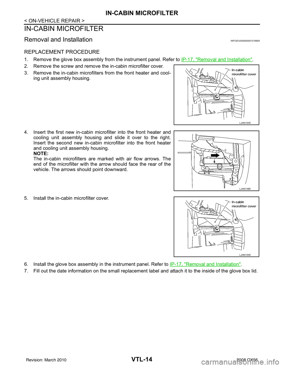
REPLACEMENT PROCEDURE
1. Remove the glove box assembly from the instrument panel. Refer to IP-17, "Removal and Installation".
2. Remove the screw and remove the in-cabin microfilter cover.
3. Remove the in-cabin microfilters from the front heater and cool- ing unit assembly housing.
4. Insert the first new in-cabin micr ofilter into the front heater and
cooling unit assembly housing and slide it over to the right.
Insert the second new in-cabin mi crofilter into the front heater
and cooling unit assembly housing.
NOTE:
The in-cabin microfilters are marked with air flow arrows. The
end of the microfilter with the arro w should face the rear of the
vehicle. The arrows should point downward.
5. Install the in-cabin microfilter cover.
6. Install the glove box assembly in the instrument panel. Refer to IP-17, "
Removal and Installation".
7. Fill out the date information on the sm all replacement label and attach it to the inside of the glove box lid.
LJIA0134E
LJIA0148E
LJIA0134E
Revision: March 2010 2008 QX56