2008 INFINITI QX56 fuses
[x] Cancel search: fusesPage 1938 of 4083

EXL-10
< FUNCTION DIAGNOSIS >
DAYTIME LIGHT SYSTEM
Component Description
INFOID:0000000001547101
After starting the engine with the parking brake released and the lighting switch in the OFF or 1ST position, the
headlamp high beam automatically turns on at a reduced intensity. With the lighting switch in the 2nd position
or with autolamps ON, the headlamps function the same as conventional light systems.
OPERATION
The BCM monitors inputs from the parking brake switch and the combination switch to determine when to acti-
vate the daytime light system. The BCM sends a dayti me light request to the IPDM E/R via the CAN commu-
nication lines. The IPDM E/R grounds the daytime light relay which in turn, provides power to the ground side
of the LH high beam lamp. Power flows backward through the LH high beam lamp to the IPDM E/R, through
the high beam fuses, through the RH high beam lamp circuit to the RH high beam lamp and on to ground. The
high beam lamps are wired in series which causes them to illuminate at a reduced intensity.
1. IPDM E/R E119, E122, E123, E124 2. Parking brake switch M11 3. BCM M18, M20 (view with instrument
panel removed)
4. Daytime running light relay E103 5. Combination switch M28 6. Combination meter M24
Revision: March 2010 2008 QX56
Page 1956 of 4083

EXL-28
< COMPONENT DIAGNOSIS >
HEADLAMP (HI) CIRCUIT
HEADLAMP (HI) CIRCUIT
DescriptionINFOID:0000000001547125
The IPDM E/R (intelligent power distribution module engine room) controls the headlamp high relay based on
inputs from the BCM via the CAN communication lines. When the headlamp high relay is energized, power
flows through fuses 34 and 35, located in the IPDM E/R. Power then flows to the front combination lamps to
the headlamp high beam.
Component Function CheckINFOID:0000000001547126
1.CHECK HEADLAMP (HI) OPERATION
WITHOUT CONTULT-III
1. Start IPDM E/R auto active test. Refer to PCS-12, "
Diagnosis Description".
2. Check that the headlamp switches to the high beam. NOTE:
HI/LO is repeated 1 second each when usi ng the IPDM E/R auto active test.
CONSULT-III
1. Select "EXTERNAL LAMP" of IPDM E/R active test item.
2. With the test item operating, check that the headlamp switches to high beam.
Does the headlamp switch to high beam?
YES >> Headlamp (HI) circuit is normal.
NO >> Refer to EXL-28, "
Diagnosis Procedure".
Diagnosis ProcedureINFOID:0000000001547127
1.CHECK HEADLAMP (HI) FUSES
1. Turn the ignition switch OFF.
2. Check that the following fuses are not open.
Is the fuse open?
YES >> Repair the harness and replace the fuse.
NO >> GO TO 2
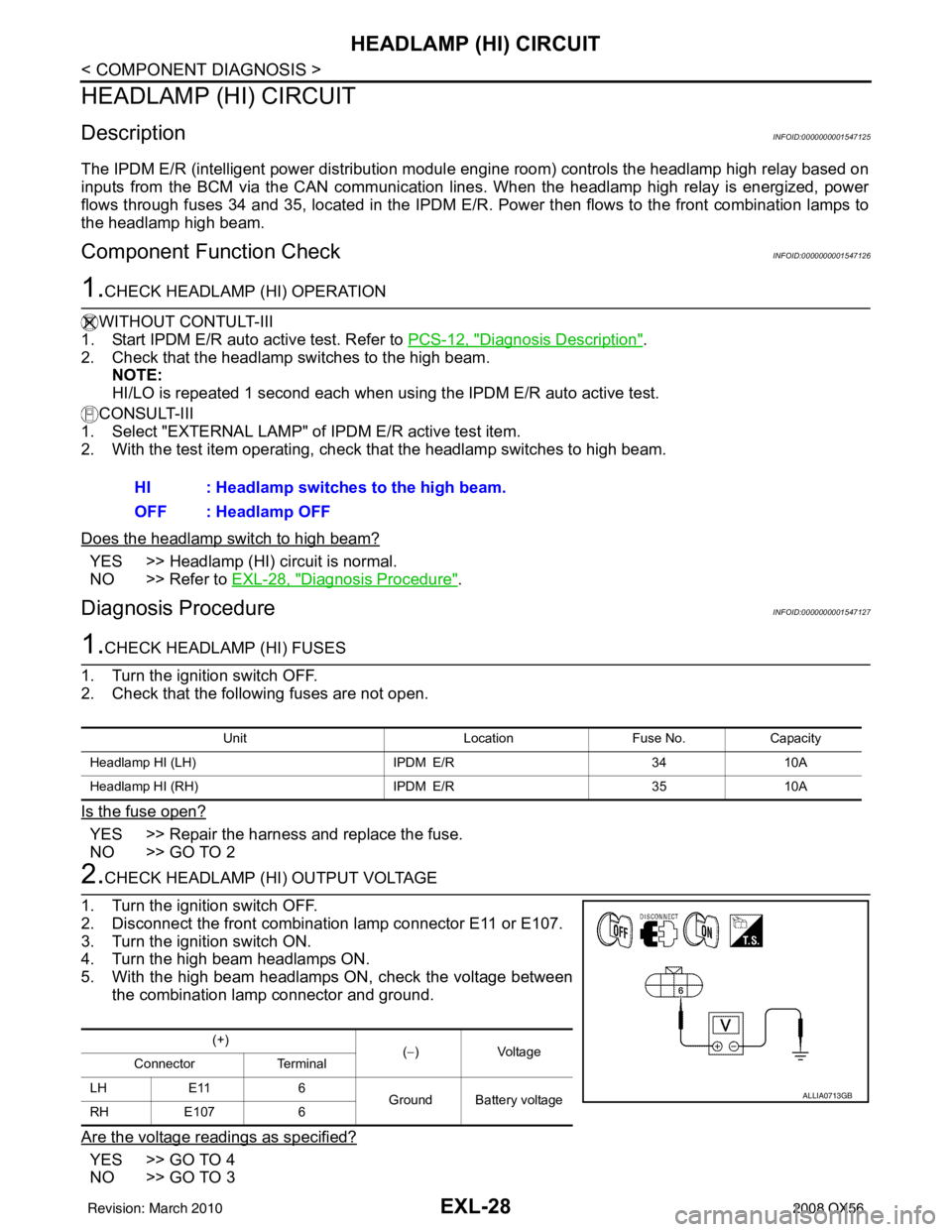
2.CHECK HEADLAMP (HI) OUTPUT VOLTAGE
1. Turn the ignition switch OFF.
2. Disconnect the front combination lamp connector E11 or E107.
3. Turn the ignition switch ON.
4. Turn the high beam headlamps ON.
5. With the high beam headlamps ON, check the voltage between the combination lamp connector and ground.
Are the voltage readings as specified?
YES >> GO TO 4
NO >> GO TO 3 HI : Headlamp switches to the high beam.
OFF : Headlamp OFF
Unit
LocationFuse No.Capacity
Headlamp HI (LH) IPDM E/R3410A
Headlamp HI (RH) IPDM E/R3510A
(+)
(−)Voltage
Connector Terminal
LH E11 6
Ground Battery voltage
RH E107 6
ALLIA0713GB
Revision: March 2010 2008 QX56
Page 1958 of 4083

EXL-30
< COMPONENT DIAGNOSIS >
HEADLAMP (LO) CIRCUIT
HEADLAMP (LO) CIRCUIT
DescriptionINFOID:0000000001547128
The IPDM E/R (intelligent power distribution module engine room) controls the headlamp low relay based on
inputs from the BCM via the CAN communication lines. When the headlamp low relay is energized, power
flows through fuses 40 and 41, located in the IPDM E/R. Power then flows to the front combination lamps to
the headlamp low beam.
Component Function CheckINFOID:0000000001547129
1.CHECK HEADLAMP (LO) OPERATION
WITHOUT CONSULT-III
1. Start IPDM E/R auto active test. Refer to PCS-12, "
Diagnosis Description".
2. Check that the headlamp is turned ON. NOTE:
HI/LO is repeated 1 second each when usi ng the IPDM E/R auto active test.
CONSULT-III
1. Select "EXTERNAL LAMP" of IPDM E/R active test item.
2. With the test items operating, check that the headlamp is turned ON.
Is the headlamp turned ON?
YES >> Headlamp (LO) is normal.
NO >> Refer to EXL-30, "
Diagnosis Procedure".
Diagnosis ProcedureINFOID:0000000001547130
1.CHECK HEADLAMP (LO) FUSES
1. Turn the ignition switch OFF.
2. Check that the following fuses are not open.
Is the fuse open?
YES >> Repair the harness and replace the fuse.
NO >> GO TO 2
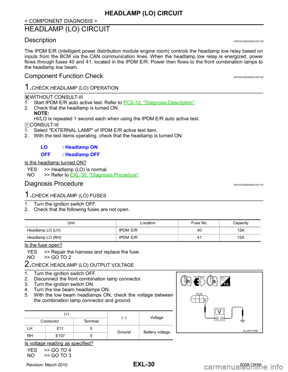
2.CHECK HEADLAMP (LO) OUTPUT VOLTAGE
1. Turn the ignition switch OFF.
2. Disconnect the front combination lamp connector.
3. Turn the ignition switch ON.
4. Turn the low beam headlamps ON.
5. With the low beam headlamps ON, check the voltage between the combination lamp connector and ground.
Is voltage reading as specified?
YES >> GO TO 4
NO >> GO TO 3 LO : Headlamp ON
OFF : Headlamp OFF
Unit
LocationFuse No.Capacity
Headlamp LO (LH) IPDM E/R4015A
Headlamp LO (RH) IPDM E/R4115A
(+)
(−)Voltage
Connector Terminal
LH E11 5 Ground Battery voltage
RH E107 5
ALLIA0716GB
Revision: March 2010 2008 QX56
Page 1960 of 4083

EXL-32
< COMPONENT DIAGNOSIS >
FRONT FOG LAMP CIRCUIT
FRONT FOG LAMP CIRCUIT
DescriptionINFOID:0000000001547131
The IPDM E/R (intelligent power distribution module engine room) controls the front fog lamp relay based on
inputs from the BCM via the CAN communication lines. When the front fog lamp relay is energized, power
flows from the front fog lamp relay in the IPDM E/R to the front fog lamps.
Component Function CheckINFOID:0000000001547132
1.CHECK FRONT FOG LAMP OPERATION
WITHOUT CONSULT-III
1. Activate IPDM E/R auto active test. Refer to PCS-12, "
Diagnosis Description".
2. Check that the front fog lamp is turned ON.
CONSULT-III
1. Select "EXTERNAL LAMP" of IPDM E/R active test item.
2. With operating the test items, Check that the front fog lamp is turned ON.
Is the front fog lamp turned ON?
YES >> Front fog lamp circuit is normal.
NO >> Refer to EXL-32, "
Diagnosis Procedure".
Diagnosis ProcedureINFOID:0000000001547133
1.CHECK FRONT FOG LAMP FUSE
1. Turn the ignition switch OFF.
2. Check that the following fuses are not open.
Is the fuse open?
YES >> Repair the harness and replace the fuse.
NO >> GO TO 2
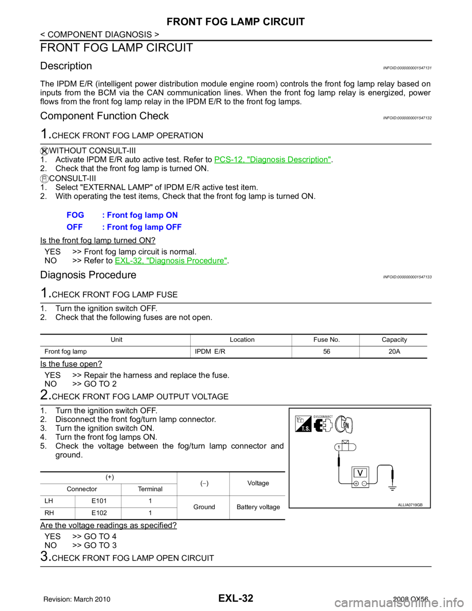
2.CHECK FRONT FOG LAMP OUTPUT VOLTAGE
1. Turn the ignition switch OFF.
2. Disconnect the front fog/turn lamp connector.
3. Turn the ignition switch ON.
4. Turn the front fog lamps ON.
5. Check the voltage between the fog/turn lamp connector and ground.
Are the voltage readings as specified?
YES >> GO TO 4
NO >> GO TO 3
3.CHECK FRONT FOG LAMP OPEN CIRCUIT FOG : Front fog lamp ON
OFF : Front fog lamp OFF
Unit
LocationFuse No.Capacity
Front fog lamp IPDM E/R5620A
(+)
(−)V olt a g e
Connector Terminal
LH E101 1
Ground Battery voltage
RH E102 1
ALLIA0719GB
Revision: March 2010 2008 QX56
Page 1962 of 4083

EXL-34
< COMPONENT DIAGNOSIS >
PARKING LAMP CIRCUIT
PARKING LAMP CIRCUIT
DescriptionINFOID:0000000001547134
The IPDM E/R (intelligent power distribution module engine room) controls the tail lamp relay based on inputs
from the BCM via the CAN communication lines. When the tail lamp relay is energized, power flows through
fuse 37, located in the IPDM E/R. Power then flows to the front and rear combination lamps.
Component Function CheckINFOID:0000000001547135
1.CHECK PARKING LAMP OPERATION
WITHOUT CONSULT-III
1. Activate IPDM E/R auto active test. Refer to PCS-12, "
Diagnosis Description".
2. Check that the parking lamp is turned ON.
CONSULT-III
1. Select "EXTERNAL LAMP" of IPDM E/R active test item.
2. With operating the test items, check that the parking lamp is turned ON.
Is the parking lamp turned ON?
YES >> Parking lamp circuit is normal.
NO >> Refer to EXL-34, "
Diagnosis Procedure".
Diagnosis ProcedureINFOID:0000000001547136
1.CHECK PARKING LAMP FUSES
1. Turn the ignition switch OFF.
2. Check that the following fuses are not open.
Is the fuse open?
YES >> Repair the harness and replace the fuse.
NO >> GO TO 2
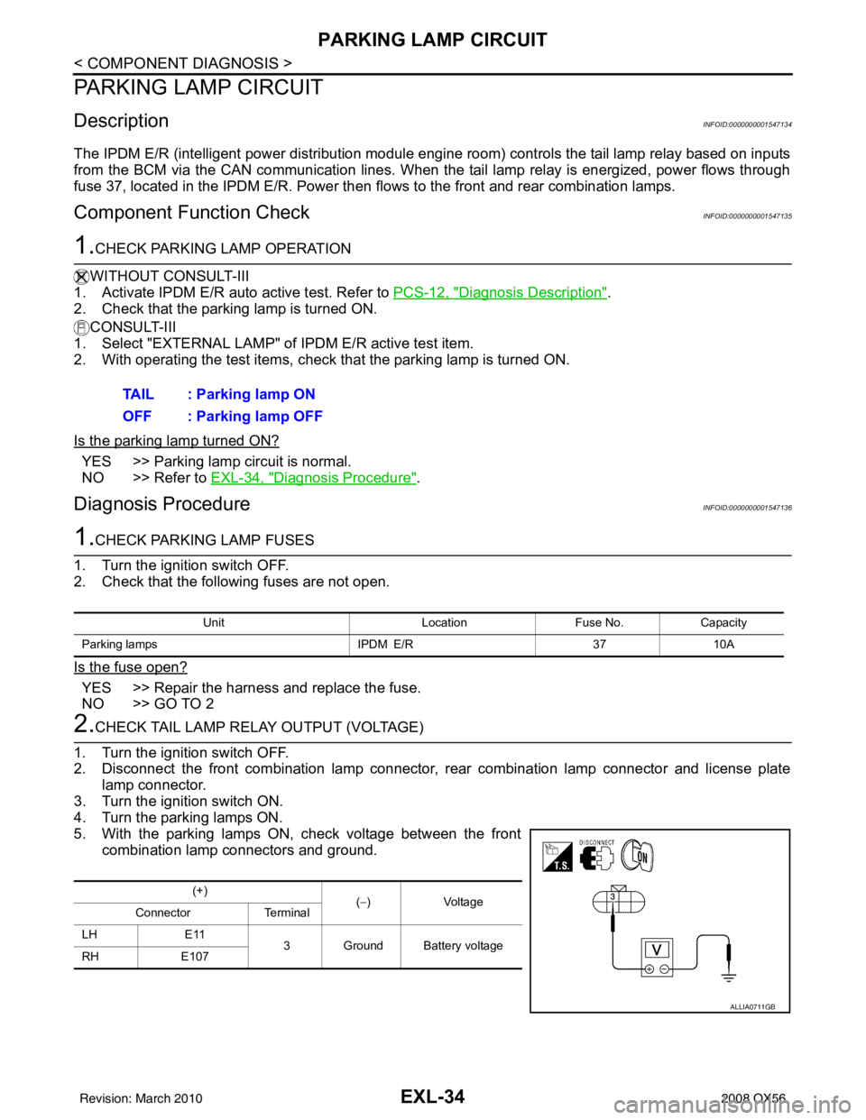
2.CHECK TAIL LAMP RELAY OUTPUT (VOLTAGE)
1. Turn the ignition switch OFF.
2. Disconnect the front combination lamp connector, rear combination lamp connector and license plate
lamp connector.
3. Turn the ignition switch ON.
4. Turn the parking lamps ON.
5. With the parking lamps ON, check voltage between the front combination lamp connectors and ground.TAIL : Parking lamp ON
OFF : Parking lamp OFF
Unit
LocationFuse No.Capacity
Parking lamps IPDM E/R3710A
(+)
(−)Voltage
Connector Terminal
LH E11
3 Ground Battery voltage
RH E107
ALLIA0711GB
Revision: March 2010 2008 QX56
Page 2304 of 4083
![INFINITI QX56 2008 Factory Service Manual BLOWER MOTOR CONTROL SYSTEMHAC-51
< COMPONENT DIAGNOSIS > [AUTOMATIC AIR CONDITIONER]
C
D
E
F
G H
J
K L
M A
B
HAC
N
O P
YES >> Refer to HAC-23, "A/C System Self-Diagnosis Code Chart".
NO >> GO TO 5.
INFINITI QX56 2008 Factory Service Manual BLOWER MOTOR CONTROL SYSTEMHAC-51
< COMPONENT DIAGNOSIS > [AUTOMATIC AIR CONDITIONER]
C
D
E
F
G H
J
K L
M A
B
HAC
N
O P
YES >> Refer to HAC-23, "A/C System Self-Diagnosis Code Chart".
NO >> GO TO 5.](/manual-img/42/57030/w960_57030-2303.png)
BLOWER MOTOR CONTROL SYSTEMHAC-51
< COMPONENT DIAGNOSIS > [AUTOMATIC AIR CONDITIONER]
C
D
E
F
G H
J
K L
M A
B
HAC
N
O P
YES >> Refer to HAC-23, "A/C System Self-Diagnosis Code Chart".
NO >> GO TO 5.
5.PERFORM A/C AND AV SWITCH ASSEMBLY SELF-DIAGNOSIS
Perform self-diagnosis to check the A/C and AV switch assembly. Refer to HAC-22, "
A/C and AV Switch
Assembly Self-Diagnosis".
Is the inspection results normal?
YES >> GO TO 6.
NO >> Replace A/C and AV switch assembly. Refer to VTL-7, "
Removal and Installation".
6.CHECK BLOWER MOTOR OPERATION
Check and verify blower motor operates manually in all speeds.
Does blower motor operate in all speeds?
YES >> GO TO 7.
NO >> Refer to HAC-51, "
Front Blower Motor Diagnosis Procedure".
7.CHECK ENGINE COOLANT TEMPERATURE SENSOR CIRCUIT
Check engine coolant temperature sensor circuit. Refer to EC-125, "
Diagnosis Procedure".
Is the inspection results normal?
YES >> GO TO 8.
NO >> Replace engine coolant temperature sensor.
8.RECHECK FOR ANY SYMPTOMS
Perform a complete operational check for any symptoms. Refer to HAC-4, "
Operational Check (Front)".
Does another symptom exist?
YES >> Refer to HAC-3, "How to Perform Trouble Diagnosis For Quick And Accurate Repair" .
NO >> Replace A/C auto amp. Refer to VTL-7, "
Removal and Installation".
Front Blower Motor Diagnosis ProcedureINFOID:0000000001679797
SYMPTOM: Blower motor operation is malfunctioning.
DIAGNOSTIC PROCEDURE FOR BLOWER MOTOR
SYMPTOM: Blower motor operation is malfunctioning under starting
blower speed control.
1.CHECK FUSES
AWIIA0174GB
Revision: March 2010 2008 QX56
Page 2305 of 4083
![INFINITI QX56 2008 Factory Service Manual HAC-52
< COMPONENT DIAGNOSIS >[AUTOMATIC AIR CONDITIONER]
BLOWER MOTOR CONTROL SYSTEM
Check 20A fuses [No. 24 and 27 (Located in the fuse and fusible link box)]. For fuse layout. Refer to
PG-70,
"Ter INFINITI QX56 2008 Factory Service Manual HAC-52
< COMPONENT DIAGNOSIS >[AUTOMATIC AIR CONDITIONER]
BLOWER MOTOR CONTROL SYSTEM
Check 20A fuses [No. 24 and 27 (Located in the fuse and fusible link box)]. For fuse layout. Refer to
PG-70,
"Ter](/manual-img/42/57030/w960_57030-2304.png)
HAC-52
< COMPONENT DIAGNOSIS >[AUTOMATIC AIR CONDITIONER]
BLOWER MOTOR CONTROL SYSTEM
Check 20A fuses [No. 24 and 27 (Located in the fuse and fusible link box)]. For fuse layout. Refer to
PG-70,
"Terminal Arrangement".
Is the inspection result normal?
YES >> GO TO 2.
NO >> GO TO 7.
2.CHECK FRONT BLOWER MOTOR POWER SUPPLY CIRCUIT
1. Turn ignition switch OFF.
2. Disconnect front blower motor connector.
3. Turn ignition switch ON.
4. Press the A/C switch.
5. Press the front blower control "+" switch to maximum speed.
6. Check voltage between front blower motor harness connector M62 terminal 2 and ground.
Is the inspection result normal?
YES >> GO TO 10.
NO >> GO TO 3.
3.CHECK FRONT BLOWER MOTOR RELAY (S WITCH SIDE) POWER SUPPLY CIRCUIT
1. Turn ignition switch OFF.
2. Disconnect front blower motor relay.
3. Check voltage between front blower motor relay harness con- nector M107 terminal 5 and ground.
Is the inspection result normal?
YES >> GO TO 4.
NO >> Repair harness or connector.
4.CHECK FRONT BLOWER MOTOR RELAY
Turn ignition switch OFF.
Check front blower motor relay. Refer to HAC-54, "
Front Blower Motor Component Inspection".
Is the inspection result normal?
YES >> GO TO 5.
NO >> Replace front blower motor relay.
5.CHECK FRONT BLOWER MOTOR RELA Y (SWITCH SIDE) CIRCUIT FOR OPEN
Check continuity between front blower motor relay harness connec-
tor M107 terminal 3 and front blower motor harness connector M62
terminal 2.
Is the inspection result normal?
YES >> GO TO 6.
NO >> Repair harness or connector.
6.CHECK FRONT BLOWER MOTOR RE LAY (COIL SIDE) POWER SUPPLY
Fuses are good.
2 - Ground
: Battery voltage
WJIA1331E
5 - Ground: Battery voltage
WJIA1886E
3 - 2 : Continuity should exist.
WJIA1360E
Revision: March 2010 2008 QX56
Page 2306 of 4083
![INFINITI QX56 2008 Factory Service Manual BLOWER MOTOR CONTROL SYSTEMHAC-53
< COMPONENT DIAGNOSIS > [AUTOMATIC AIR CONDITIONER]
C
D
E
F
G H
J
K L
M A
B
HAC
N
O P
1. Turn ignition switch ON.
2. Check voltage between front blower motor relay ha INFINITI QX56 2008 Factory Service Manual BLOWER MOTOR CONTROL SYSTEMHAC-53
< COMPONENT DIAGNOSIS > [AUTOMATIC AIR CONDITIONER]
C
D
E
F
G H
J
K L
M A
B
HAC
N
O P
1. Turn ignition switch ON.
2. Check voltage between front blower motor relay ha](/manual-img/42/57030/w960_57030-2305.png)
BLOWER MOTOR CONTROL SYSTEMHAC-53
< COMPONENT DIAGNOSIS > [AUTOMATIC AIR CONDITIONER]
C
D
E
F
G H
J
K L
M A
B
HAC
N
O P
1. Turn ignition switch ON.
2. Check voltage between front blower motor relay harness con- nector M107 terminal 2 and ground.
Is the inspection result normal?
YES >> Repair front blower motor ground circuit or connector.
NO >> Repair harness or connector.
7.REPLACE FUSES
Replace fuses.
Does the fuse blow?
YES >> • If fuse blows without activating the front blower motor, repair short between fuse and front blower motor relay.
• If fuse blows activating the front blower motor, GO TO 8.
NO >> Inspection End.
8.CHECK FRONT BLOWER MOTOR POWER SUPPLY CIRCUIT FOR SHORT
1. Turn ignition switch OFF.
2. Disconnect front blower motor connector, front blower motor relay and variable blower control connector.
3. Check continuity between variable blower control harness con- nector M122 terminal 4 and ground.
Is the inspection result normal?
YES >> GO TO 9.
NO >> Repair harness or connector.
9.CHECK FRONT BLOWER MOTOR
Check front blower motor. Refer to HAC-54, "
Front Blower Motor Component Inspection".
Is the inspection result normal?
YES >> Replace variable blower control (front). Refer to VTL-29, "Removal and Installation".
NO >> Replace front blower motor. Refer to VTL-12, "
Removal and Installation".
10.CHECK FRONT BLOWER MOTOR
Check front blower motor. Refer to HAC-54, "
Front Blower Motor Component Inspection".
Is the inspection result normal?
YES >> GO TO 11.
NO >> Replace front blower motor. Refer to VTL-12, "
Removal and Installation".
11 .CHECK BLOWER MOTOR GROUND CIRCUIT
1. Disconnect variable blower control connector.
2. Check continuity between front blower motor harness connector M62 (B) terminal 1 and variable blower control harness connec-
tor M122 (A) terminal 2.
Is the inspection result normal?
YES >> GO TO 12.
NO >> Repair harness or connector. 2 - Ground : Battery voltage
WJIA1363E
4 - Ground
: Continuity should not exist.
AWIIA0177ZZ
1 - 2 : Continuity should exist.
AWIIA0179ZZ
Revision: March 2010 2008 QX56