2008 INFINITI QX56 engine oil
[x] Cancel search: engine oilPage 2617 of 4083
ENGINE MAINTENANCEMA-19
< ON-VEHICLE MAINTENANCE >
C
DE
F
G H
I
J
K L
M B
MA
N
O A
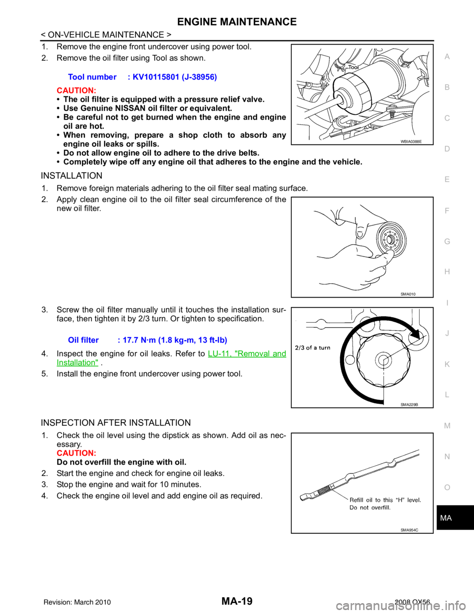
1. Remove the engine front undercover using power tool.
2. Remove the oil filter using Tool as shown.
CAUTION:
• The oil filter is equipped with a pressure relief valve.
• Use Genuine NISSAN oil filter or equivalent.
• Be careful not to get burned when the engine and engine
oil are hot.
• When removing, prepare a s hop cloth to absorb any
engine oil leaks or spills.
• Do not allow engine oil to adhere to the drive belts.
• Completely wipe off any engine oil that adheres to the engine and the vehicle.
INSTALLATION
1. Remove foreign materials adhering to the oil filter seal mating surface.
2. Apply clean engine oil to the oil filter seal circumference of the
new oil filter.
3. Screw the oil filter manually unt il it touches the installation sur-
face, then tighten it by 2/3 turn. Or tighten to specification.
4. Inspect the engine for oil leaks. Refer to LU-11, "
Removal and
Installation" .
5. Install the engine front undercover using power tool.
INSPECTION AFTER INSTALLATION
1. Check the oil level using the dipstick as shown. Add oil as nec- essary.
CAUTION:
Do not overfill th e engine with oil.
2. Start the engine and check for engine oil leaks.
3. Stop the engine and wait for 10 minutes.
4. Check the engine oil level and add engine oil as required. Tool number : KV10115801 (J-38956)
WBIA0388E
SMA010
Oil filter : 17.7 N·m (1.8 kg-m, 13 ft-lb)
SMA229B
SMA954C
Revision: March 2010
2008 QX56
Page 2618 of 4083
MA-20
< ON-VEHICLE MAINTENANCE >
ENGINE MAINTENANCE
Changing Spark Plugs
INFOID:0000000001606177
REMOVAL
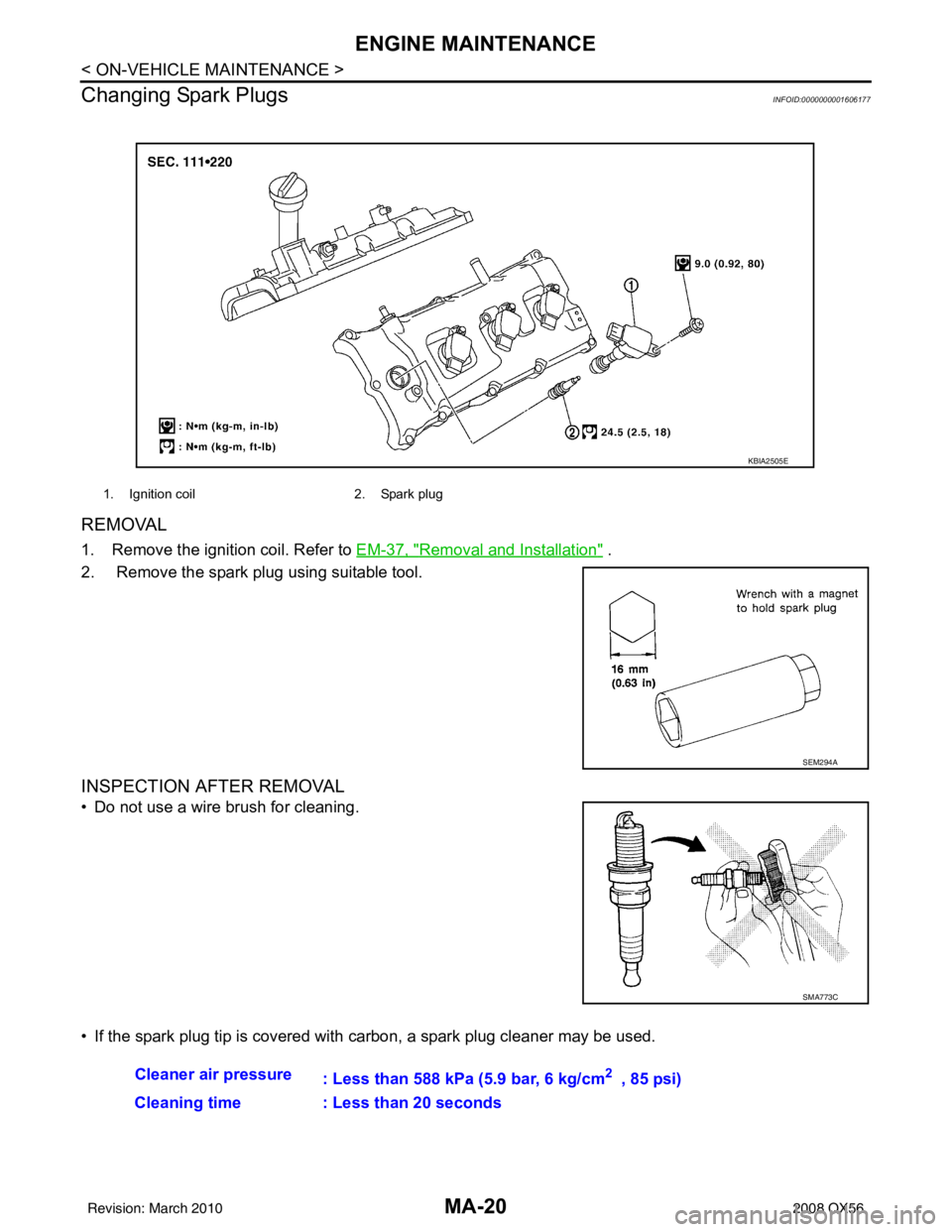
1. Remove the ignition coil. Refer to EM-37, "Removal and Installation" .
2. Remove the spark plug using suitable tool.
INSPECTION AFTER REMOVAL
• Do not use a wire brush for cleaning.
• If the spark plug tip is covered with carbon, a spark plug cleaner may be used.
1. Ignition coil 2. Spark plug
KBIA2505E
SEM294A
SMA773C
Cleaner air pressure
: Less than 588 kPa (5.9 bar, 6 kg/cm2 , 85 psi)
Cleaning time : Less than 20 seconds
Revision: March 2010 2008 QX56
Page 2623 of 4083
CHASSIS AND BODY MAINTENANCEMA-25
< ON-VEHICLE MAINTENANCE >
C
DE
F
G H
I
J
K L
M B
MA
N
O A
10. Tighten the level gauge bolt to specification.
Changing Automatic Transmission Fluid (ATF)INFOID:0000000001606182
1. Drive the vehicle to warm up the ATF to 80
° C (176 ° F).
2. Stop the engine.
3. Remove the ATF level gauge bolt.
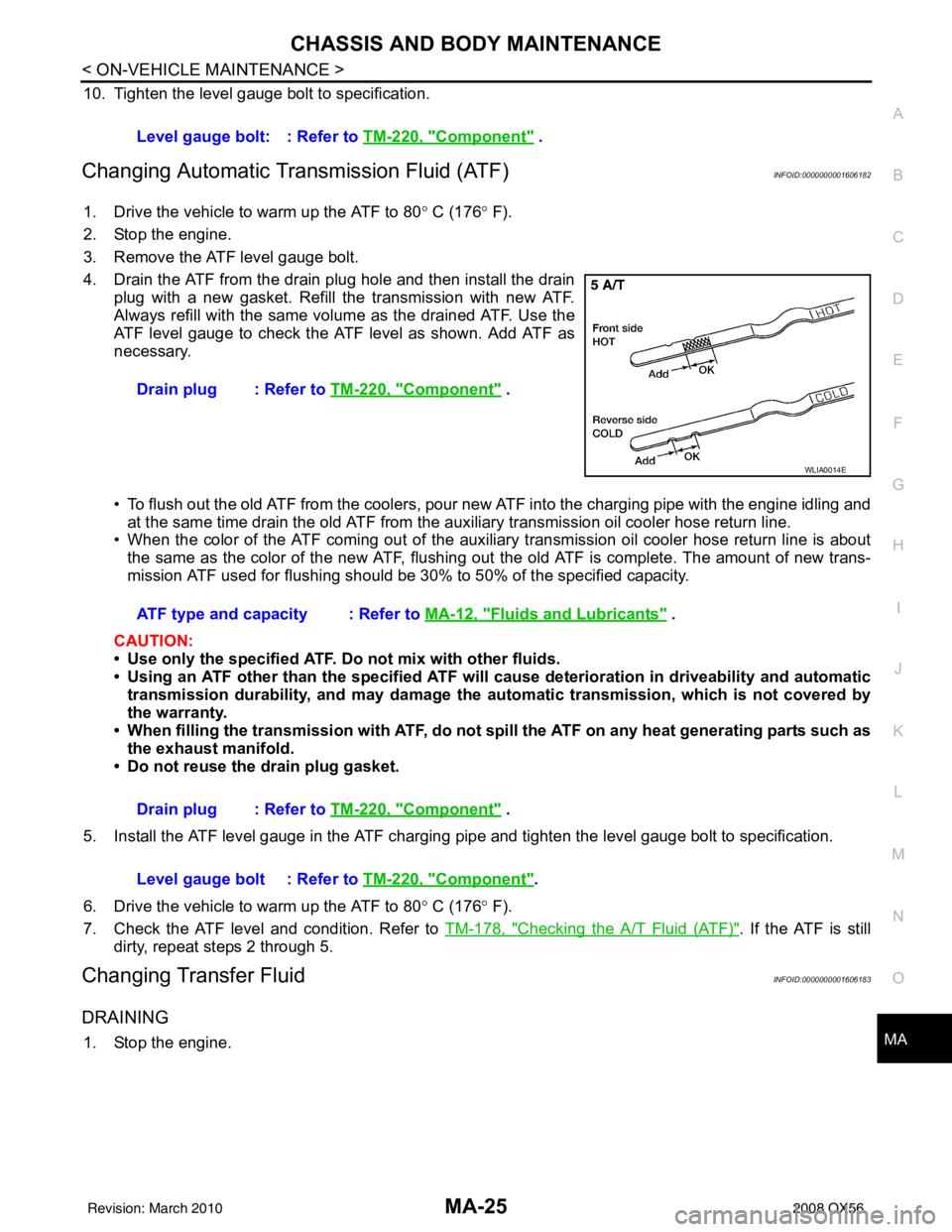
4. Drain the ATF from the drain plug hole and then install the drain plug with a new gasket. Refill the transmission with new ATF.
Always refill with the same volume as the drained ATF. Use the
ATF level gauge to check the ATF level as shown. Add ATF as
necessary.
• To flush out the old ATF from the coolers, pour new ATF into the charging pipe with the engine idling and
at the same time drain the old ATF from the aux iliary transmission oil cooler hose return line.
• When the color of the ATF coming out of the auxiliary transmission oil cooler hose return line is about
the same as the color of the new ATF, flushing out the old ATF is complete. The amount of new trans-
mission ATF used for flushing should be 30% to 50% of the specified capacity.
CAUTION:
• Use only the specified ATF. Do not mix with other fluids.
• Using an ATF other than the speci fied ATF will cause deterioration in driveability and automatic
transmission durability, and may damage the au tomatic transmission, which is not covered by
the warranty.
• When filling the transmission with ATF, do not spill the ATF on any heat generating parts such as the exhaust manifold.
• Do not reuse the drain plug gasket.
5. Install the ATF level gauge in the ATF charging pipe and tighten the level gauge bolt to specification.
6. Drive the vehicle to warm up the ATF to 80 ° C (176 ° F).
7. Check the ATF level and condition. Refer to TM-178, "
Checking the A/T Fluid (ATF)". If the ATF is still
dirty, repeat steps 2 through 5.
Changing Transfer FluidINFOID:0000000001606183
DRAINING
1. Stop the engine. Level gauge bolt: : Refer to
TM-220, "
Component" .
Drain plug : Refer to TM-220, "
Component" .
WLIA0014E
ATF type and capacity : Refer to MA-12, "Fluids and Lubricants" .
Drain plug : Refer to TM-220, "
Component" .
Level gauge bolt : Refer to TM-220, "
Component".
Revision: March 2010 2008 QX56
Page 2624 of 4083
MA-26
< ON-VEHICLE MAINTENANCE >
CHASSIS AND BODY MAINTENANCE
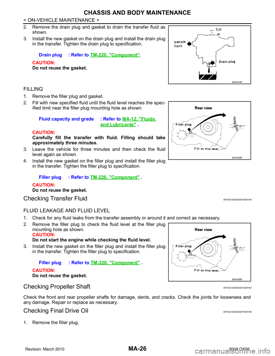
2. Remove the drain plug and gasket to drain the transfer fluid asshown.
3. Install the new gasket on the drain plug and install the drain plug in the transfer. Tighten the drain plug to specification.
CAUTION:
Do not reuse the gasket.
FILLING
1. Remove the filler plug and gasket.
2. Fill with new specified fluid until the fluid level reaches the spec-
ified limit near the filler plug mounting hole as shown.
CAUTION:
Carefully fill the transfer wi th fluid. Filling should take
approximately three minutes.
3. Leave the vehicle for three minutes and then check the fluid level again as shown.
4. Install the new gasket on the filler plug and install the filler plug in the transfer. Tighten the filler plug to specification.
CAUTION:
Do not reuse the gasket.
Checking Transfer FluidINFOID:0000000001606184
FLUID LEAKAGE AND FLUID LEVEL
1. Check for any fluid leaks from the transfer assembly or around it and correct as necessary.
2. Remove the filler plug to check the fluid level at the filler plugmounting hole as shown.
CAUTION:
Do not start the engine wh ile checking the fluid level.
3. Install the new gasket on the filler plug and install the filler plug in the transfer. Tighten the filler plug to specification.
CAUTION:
Do not reuse the gasket.
Checking Propeller ShaftINFOID:0000000001606185
Check the front and rear propeller shafts for damage, dents, and cracks. Check the joints for looseness and
any damage. Repair or replace as necessary.
Checking Final Drive OilINFOID:0000000001606186
1. Remove the filler plug. Drain plug : Refer to
TM-220, "
Component".
SMA444B
Fluid capacity and grade : Refer to MA-12, "Fluids
and Lubricants" .
Filler plug : Refer to TM-220, "
Component" .
SMA439B
Filler plug : Refer to TM-220, "Component" .
SMA439B
Revision: March 2010 2008 QX56
Page 2629 of 4083
CHASSIS AND BODY MAINTENANCEMA-31
< ON-VEHICLE MAINTENANCE >
C
DE
F
G H
I
J
K L
M B
MA
N
O A
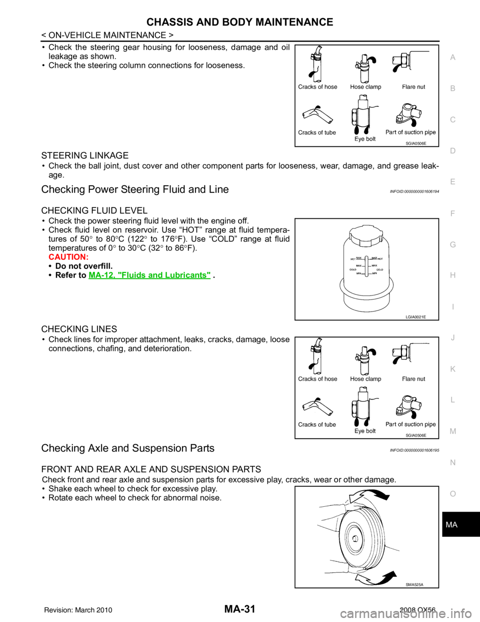
• Check the steering gear housing for looseness, damage and oil
leakage as shown.
• Check the steering column connections for looseness.
STEERING LINKAGE
• Check the ball joint, dust cover and other component parts for looseness, wear, damage, and grease leak-
age.
Checking Power Steering Fluid and LineINFOID:0000000001606194
CHECKING FLUID LEVEL
• Check the power steering fluid level with the engine off.
• Check fluid level on reservoir. Use “HOT” range at fluid tempera- tures of 50 ° to 80° C (122° to 176° F). Use “COLD” range at fluid
temperatures of 0 ° to 30° C (32° to 86° F).
CAUTION:
• Do not overfill.
• Refer to MA-12, "
Fluids and Lubricants" .
CHECKING LINES
• Check lines for improper attachment, leaks, cracks, damage, loose
connections, chafing, and deterioration.
Checking Axle and Suspension PartsINFOID:0000000001606195
FRONT AND REAR AXLE AND SUSPENSION PARTS
Check front and rear axle and suspension parts for excessive play, cracks, wear or other damage.
• Shake each wheel to check for excessive play.
• Rotate each wheel to check for abnormal noise.
SGIA0506E
LGIA0021E
SGIA0506E
SMA525A
Revision: March 2010 2008 QX56
Page 2646 of 4083
MWI
MWI-1
DRIVER INFORMATION & MULTIMEDIA
C
DE
F
G H
I
J
K L
M B
SECTION MWI
A
O P
CONTENTS
METER, WARNING LAMP & INDICATOR
BASIC INSPECTION ....... .............................4
DIAGNOSIS AND REPAIR WORKFLOW ..... .....4
Work Flow ........................................................... ......4
FUNCTION DIAGNOSIS ...............................5
METER SYSTEM ............................................ .....5
METER SYSTEM .........................................................5
METER SYSTEM : System Diagram ........................5
METER SYSTEM : System Description ....................5
METER SYSTEM : Arrangem ent of Combination
Meter ................................................................... ......
6
METER SYSTEM : Component Parts Location ........7
METER SYSTEM : Component Description ....... ......7
SPEEDOMETER ..........................................................8
SPEEDOMETER : System Diagram ................... ......8
SPEEDOMETER : System Description .....................8
SPEEDOMETER : Component Parts Location .........9
SPEEDOMETER : Component Description ........ ......9
TACHOMETER ...................................................... ......9
TACHOMETER : System Diagram ...........................9
TACHOMETER : System De scription .....................10
TACHOMETER : Component Parts Location ..... ....10
TACHOMETER : Component Description ..............10
ENGINE COOLANT TEMPERATURE GAUGE .... ....10
ENGINE COOLANT TEMPERATURE GAUGE :
System Diagram ......................................................
11
ENGINE COOLANT TEMPERATURE GAUGE :
System Description .................................................
11
ENGINE COOLANT TEMPERATURE GAUGE :
Component Parts Location ......................................
11
ENGINE COOLANT TEMPERATURE GAUGE :
Component Description ...........................................
12
FUEL GAUGE ........................................................ ....12
FUEL GAUGE : System Diagram ...........................12
FUEL GAUGE : System Description .......................12
FUEL GAUGE : Component Parts Location ...........12
FUEL GAUGE : Component Description ............. ....13
ENGINE OIL PRESSURE GAUGE ............................13
ENGINE OIL PRESSURE GAUGE : System Dia-
gram .................................................................... ....
13
ENGINE OIL PRESSURE GAUGE : System De-
scription ...................................................................
13
ENGINE OIL PRESSURE GAUGE : Component
Parts Location ..........................................................
14
ENGINE OIL PRESSURE GAUGE : Component
Description ...............................................................
14
VOLTAGE GAUGE ................................................ ....14
VOLTAGE GAUGE : System Diagram ....................15
VOLTAGE GAUGE : System Description ................15
VOLTAGE GAUGE : Component Parts Location ....15
VOLTAGE GAUGE : Component Description .........16
ODO/TRIP METER ................................................. ....16
ODO/TRIP METER : System Diagram ....................16
ODO/TRIP METER : System Description ................16
ODO/TRIP METER : Component Parts Location ....16
ODO/TRIP METER : Component Description .........17
SHIFT POSITION INDICATOR .............................. ....17
SHIFT POSITION INDICATOR : System Diagram ....17
SHIFT POSITION INDICATOR : System Descrip-
tion ...........................................................................
17
SHIFT POSITION INDICATOR : Component
Parts Location ..........................................................
18
SHIFT POSITION INDICATOR : Component De-
scription ............................................................... ....
18
WARNING LAMPS/INDICATOR LAMPS .............. ....18
WARNING LAMPS/INDICATOR LAMPS : System
Diagram ............................................................... ....
18
WARNING LAMPS/INDICATOR LAMPS : System
Description ........................................................... ....
19
WARNING LAMPS/INDICATOR LAMPS : Com-
ponent Parts Location ..............................................
19
WARNING LAMPS/INDICATOR LAMPS : Com-
ponent Description ...................................................
19
Revision: March 2010 2008 QX56
Page 2647 of 4083

MWI-2
INFORMATION DISPLAY .........................................19
INFORMATION DISPLAY : System Diagram .........20
INFORMATION DISPLAY : System Description ....20
INFORMATION DISPLAY : Component Parts Lo-
cation ................................................................... ...
21
INFORMATION DISPLAY : Component Descrip-
tion ....................................................................... ...
21
COMPASS .........................................................22
Description ........................................................... ...22
DIAGNOSIS SYSTEM (METER) .......................24
Diagnosis Description .......................................... ...24
CONSULT-III Function (METER/M&A) ................ ...25
COMPONENT DIAGNOSIS ........................28
DTC U1000 CAN COMMUNICATION ............ ...28
DTC Logic ............................................................ ...28
Diagnosis Procedure .............................................28
DTC B2205 VEHICLE SPEED CIRCUIT ...........29
Description ........................................................... ...29
DTC Logic ...............................................................29
Diagnosis Procedure .............................................29
POWER SUPPLY AND GROUND CIRCUIT .....30
COMBINATION METER ........................................ ...30
COMBINATION METER : Diagnosis Procedure ....30
BCM (BODY CONTROL MODULE) ...................... ...30
BCM (BODY CONTROL MODULE) : Diagnosis
Procedure ...............................................................
31
IPDM E/R (INTELLIGENT POWER DISTRIBU-
TION MODULE ENGINE ROOM) .......................... ...
31
IPDM E/R (INTELLIGENT POWER DISTRIBU-
TION MODULE ENGINE ROOM) : Diagnosis Pro-
cedure .....................................................................
31
FUEL LEVEL SENSOR SIGNAL CIRCUIT .......33
Description ........................................................... ...33
Component Function Check ...................................33
Diagnosis Procedure .............................................33
Component Inspection ............................................34
OIL PRESSURE SWITCH SIGNAL CIRCUIT ...35
Description ..............................................................35
Component Function Check ...................................35
Diagnosis Procedure ..............................................35
Component Inspection ............................................35
PARKING BRAKE SWITCH SIGNAL CIR-
CUIT ...................................................................
36
Description ........................................................... ...36
Component Function Check ...................................36
Diagnosis Procedure ..............................................36
Component Inspection ............................................36
WASHER LEVEL SWITCH SIGNAL CIRCUIT ...37
Description ........................................................... ...37
Diagnosis Procedure ............................................ ...37
Component Inspection ............................................37
COMPASS .........................................................38
Wiring Diagram .................................................... ...38
CLOCK ..............................................................40
Wiring Diagram .................................................... ...40
ECU DIAGNOSIS .......................................42
COMBINATION METER ................................. ...42
Reference Value .................................................. ...42
Wiring Diagram .......................................................44
Fail Safe ..................................................................61
DTC Index ...............................................................62
BCM (BODY CONTROL MODULE) ..................64
Reference Value .................................................. ...64
Terminal Layout ......................................................64
Physical Values .......................................................64
Wiring Diagram .......................................................64
DTC Inspection Priority Chart ...............................64
DTC Index ..............................................................64
IPDM E/R (INTELLIGENT POWER DISTRI-
BUTION MODULE ENGINE ROOM) .................
65
Reference Value .................................................. ...65
Terminal Layout ......................................................65
Physical Values .......................................................65
Wiring Diagram .......................................................65
Fail Safe .................................................................65
DTC Index ..............................................................65
SYMPTOM DIAGNOSIS ............................66
THE FUEL GAUGE POINTER DOES NOT
MOVE .............................................................. ...
66
Description ........................................................... ...66
Diagnosis Procedure ...............................................66
THE FUEL GAUGE POINTER DOES NOT
MOVE TO "F" WHEN REFUELING ..................
67
Description ........................................................... ...67
Diagnosis Procedure ...............................................67
THE OIL PRESSURE WARNING LAMP
DOES NOT TURN ON .................................... ...
68
Description ........................................................... ...68
Diagnosis Procedure ...............................................68
THE OIL PRESSURE WARNING LAMP
DOES NOT TURN OFF .................................. ...
69
Description ........................................................... ...69
Diagnosis Procedure ...............................................69
THE PARKING BRAKE RELEASE WARNING
CONTINUES DISPLAYING, OR DOES NOT
DISPLAY ............................................................
70
Description ........................................................... ...70
Diagnosis Procedure ...............................................70
Revision: March 2010 2008 QX56
Page 2650 of 4083
MWI
METER SYSTEMMWI-5
< FUNCTION DIAGNOSIS >
C
DE
F
G H
I
J
K L
M B A
O P
FUNCTION DIAGNOSIS
METER SYSTEM
METER SYSTEM
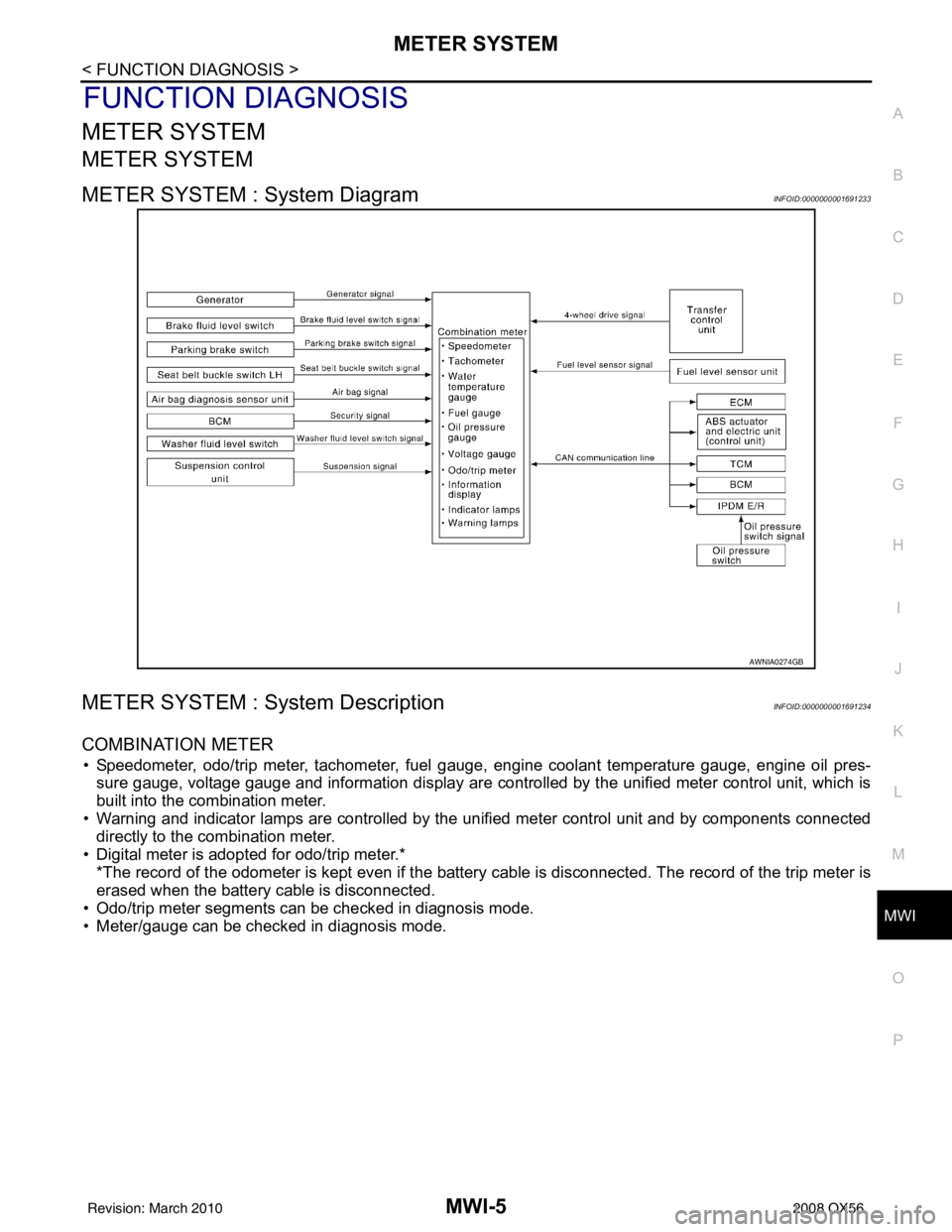
METER SYSTEM : System DiagramINFOID:0000000001691233
METER SYSTEM : System DescriptionINFOID:0000000001691234
COMBINATION METER
• Speedometer, odo/trip meter, tachometer, fuel gauge, engine coolant temperature gauge, engine oil pres-
sure gauge, voltage gauge and information display are controlled by the unified meter control unit, which is
built into the combination meter.
• Warning and indicator lamps are controlled by the unified meter control unit and by components connected directly to the combination meter.
• Digital meter is adopted for odo/trip meter.* *The record of the odometer is kept even if the battery cable is disconnected. The record of the trip meter is
erased when the battery cable is disconnected.
• Odo/trip meter segments can be checked in diagnosis mode.
• Meter/gauge can be checked in diagnosis mode.
AWNIA0274GB
Revision: March 2010 2008 QX56