2008 INFINITI QX56 ignition
[x] Cancel search: ignitionPage 3665 of 4083
TM-118
< SYMPTOM DIAGNOSIS >
SYSTEM SYMPTOM
SYMPTOM DIAGNOSIS
SYSTEM SYMPTOM
A/T Check Indicator Lamp Does Not Come OnINFOID:0000000001604179
SYMPTOM:
AT CHECK indicator lamp does not come on for about 2 seconds when turning ignition switch to
“ON”.
DIAGNOSTIC PROCEDURE
1.CHECK CAN COMMUNICATION LINE
Perform the self-diagnosis. Refer to TM-32, "
CONSULT-III Function (TRANSMISSION)".
Is a malfunction in the CAN communication indicated in the results?
YES >> Check CAN communication line. Refer to TM-21, "CAN Communication".
NO >> GO TO 2.
2.CHECK A/T CHECK INDICATOR LAMP CIRCUIT
Check the combination meter. Refer to MWI-19, "
WARNING LAMPS/INDICATOR LAMPS : System Descrip-
tion".
OK or NG
OK >> GO TO 3.
NG >> Repair or replace damaged parts.
3.CHECK TCM POWER SUPPLY AND GROUND CIRCUIT
Check TCM power supply and ground circuit. Refer to TM-92, "
Diagnosis Procedure".
OK or NG
OK >> INSPECTION END
NG >> Repair or replace damaged parts.
Engine Cannot Be Started in "P" or "N" PositionINFOID:0000000001604180
SYMPTOM:
•Engine cannot be started with select or lever in “P” or “N” position.
• Engine can be started with selector lever in “D”or “R” position.
DIAGNOSTIC PROCEDURE
1.CHECK SELF-DIAGNOSIS RESULTS
Perform self-diagnosis. Refer to TM-32, "
CONSULT-III Function (TRANSMISSION)".
Do the self-diagnosis results indicate transmission range switch?
YES >> Check the malfunctioning system. Refer to TM-43, "Diagnosis Procedure".
NO >> GO TO 2.
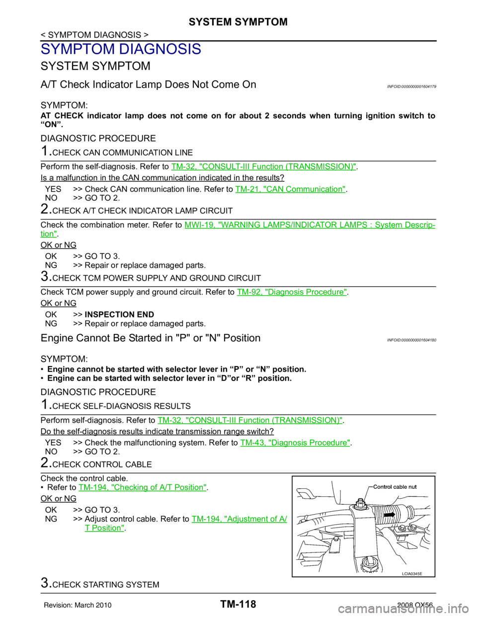
2.CHECK CONTROL CABLE
Check the control cable.
• Refer to TM-194, "
Checking of A/T Position".
OK or NG
OK >> GO TO 3.
NG >> Adjust control cable. Refer to TM-194, "
Adjustment of A/
T Position".
3.CHECK STARTING SYSTEM
LCIA0345E
Revision: March 2010 2008 QX56
Page 3668 of 4083
SYSTEM SYMPTOMTM-121
< SYMPTOM DIAGNOSIS >
CEF
G H
I
J
K L
M A
B
TM
N
O P
OK >> INSPECTION END
NG >> Repair or replace damaged parts.
Large Shock("N" to "D" Position)INFOID:0000000001604183
SYMPTOM:
A noticeable shock occurs when the selector lever is shifted from the “N” to “D” position.
DIAGNOSTIC PROCEDURE
1.CHECK SELF-DIAGNOSTIC RESULTS
Perform self-diagnosis. Refer to TM-32, "
CONSULT-III Function (TRANSMISSION)".
Do the self-diagnostic results indicate A/T fluid temperature sensor, engine speed signal, accelerator pedal
position sensor, front brake solenoid valve, CAN communication line?
YES >> Check the malfunctioning system. Refer to TM-71, "Diagnosis Procedure", TM-51, "Diagnosis
Procedure", TM-69, "Diagnosis Procedure", TM-82, "Diagnosis Procedure", TM-38, "Diagnosis
Procedure".
NO >> GO TO 2.
2.ENGINE IDLE SPEED
Check the engine idle speed. Refer to EC-17, "
Idle Speed and Ignition Timing Check".
OK or NG
OK >> GO TO 3.
NG >> Repair.
3.CHECK CONTROL CABLE
Check the control cable.
• Refer to TM-194, "
Checking of A/T Position".
OK or NG
OK >> GO TO 4.
NG >> Adjust control cable. Refer to TM-194, "
Adjustment of A/
T Position".
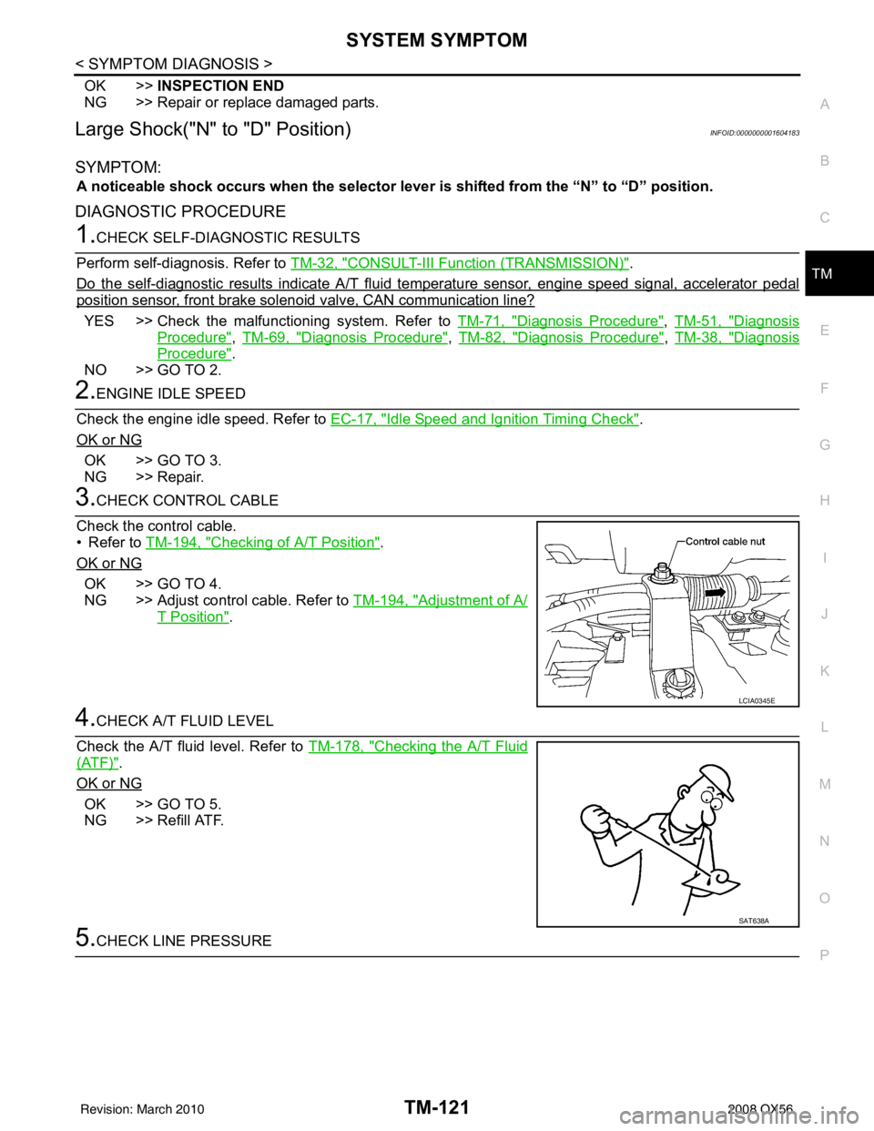
4.CHECK A/T FLUID LEVEL
Check the A/T fluid level. Refer to TM-178, "
Checking the A/T Fluid
(ATF)".
OK or NG
OK >> GO TO 5.
NG >> Refill ATF.
5.CHECK LINE PRESSURE
LCIA0345E
SAT638A
Revision: March 2010 2008 QX56
Page 3689 of 4083
TM-142
< SYMPTOM DIAGNOSIS >
SYSTEM SYMPTOM
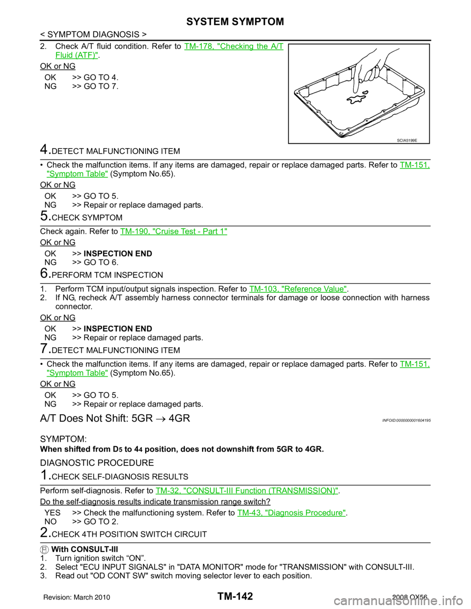
2. Check A/T fluid condition. Refer to TM-178, "Checking the A/T
Fluid (ATF)".
OK or NG
OK >> GO TO 4.
NG >> GO TO 7.
4.DETECT MALFUNCTIONING ITEM
• Check the malfunction items. If any items are dam aged, repair or replace damaged parts. Refer to TM-151,
"Symptom Table" (Symptom No.65).
OK or NG
OK >> GO TO 5.
NG >> Repair or replace damaged parts.
5.CHECK SYMPTOM
Check again. Refer to TM-190, "
Cruise Test - Part 1"
OK or NG
OK >>INSPECTION END
NG >> GO TO 6.
6.PERFORM TCM INSPECTION
1. Perform TCM input/output signals inspection. Refer to TM-103, "
Reference Value".
2. If NG, recheck A/T assembly harness connector terminals for damage or loose connection with harness
connector.
OK or NG
OK >> INSPECTION END
NG >> Repair or replace damaged parts.
7.DETECT MALFUNCTIONING ITEM
• Check the malfunction items. If any items are dam aged, repair or replace damaged parts. Refer to TM-151,
"Symptom Table" (Symptom No.65).
OK or NG
OK >> GO TO 5.
NG >> Repair or replace damaged parts.
A/T Does Not Shift: 5GR → 4GRINFOID:0000000001604195
SYMPTOM:
When shifted from D5 to 44 position, does not downshift from 5GR to 4GR.
DIAGNOSTIC PROCEDURE
1.CHECK SELF-DIAGNOSIS RESULTS
Perform self-diagnosis. Refer to TM-32, "
CONSULT-III Function (TRANSMISSION)".
Do the self-diagnosis results indicate transmission range switch?
YES >> Check the malfunctioning system. Refer to TM-43, "Diagnosis Procedure".
NO >> GO TO 2.
2.CHECK 4TH POSITION SWITCH CIRCUIT
With CONSULT-III
1. Turn ignition switch “ON”.
2. Select "ECU INPUT SIGNALS" in "DATA MONITO R" mode for "TRANSMISSION" with CONSULT-III.
3. Read out "OD CONT SW" switch moving selector lever to each position.
SCIA5199E
Revision: March 2010 2008 QX56
Page 3690 of 4083
SYSTEM SYMPTOMTM-143
< SYMPTOM DIAGNOSIS >
CEF
G H
I
J
K L
M A
B
TM
N
O P
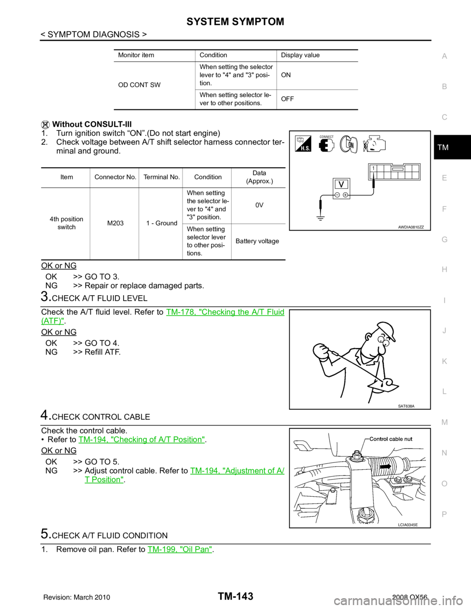
Without CONSULT-III
1. Turn ignition switch “ON”.(Do not start engine)
2. Check voltage between A/T shift selector harness connector ter- minal and ground.
OK or NG
OK >> GO TO 3.
NG >> Repair or replace damaged parts.
3.CHECK A/T FLUID LEVEL
Check the A/T fluid level. Refer to TM-178, "
Checking the A/T Fluid
(ATF)".
OK or NG
OK >> GO TO 4.
NG >> Refill ATF.
4.CHECK CONTROL CABLE
Check the control cable.
• Refer to TM-194, "
Checking of A/T Position".
OK or NG
OK >> GO TO 5.
NG >> Adjust control cable. Refer to TM-194, "
Adjustment of A/
T Position".
5.CHECK A/T FLUID CONDITION
1. Remove oil pan. Refer to TM-199, "
Oil Pan".
Monitor itemConditionDisplay value
OD CONT SW When setting the selector
lever to "4"
and "3" posi-
tion. ON
When setting selector le-
ver to other positions. OFF
Item Connector No. Terminal No. Condition Data
(Approx.)
4th position switch M203 1 - Ground When setting
the selector le-
ver to "4" and
"3" position.
0V
When setting
selector lever
to other posi-
tions. Battery voltage
AWDIA0810ZZ
SAT638A
LCIA0345E
Revision: March 2010
2008 QX56
Page 3694 of 4083
SYSTEM SYMPTOMTM-147
< SYMPTOM DIAGNOSIS >
CEF
G H
I
J
K L
M A
B
TM
N
O P
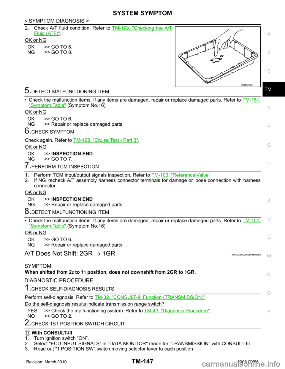
2. Check A/T fluid condition. Refer to TM-178, "Checking the A/T
Fluid (ATF)".
OK or NG
OK >> GO TO 5.
NG >> GO TO 8.
5.DETECT MALFUNCTIONING ITEM
• Check the malfunction items. If any items are damaged, repair or replace damaged parts. Refer to TM-151,
"Symptom Table" (Symptom No.16).
OK or NG
OK >> GO TO 6.
NG >> Repair or replace damaged parts.
6.CHECK SYMPTOM
Check again. Refer to TM-193, "
Cruise Test - Part 3".
OK or NG
OK >> INSPECTION END
NG >> GO TO 7.
7.PERFORM TCM INSPECTION
1. Perform TCM input/output signals inspection. Refer to TM-103, "
Reference Value".
2. If NG, recheck A/T assembly harness connector terminals for damage or loose connection with harness connector.
OK or NG
OK >> INSPECTION END
NG >> Repair or replace damaged parts.
8.DETECT MALFUNCTIONING ITEM
• Check the malfunction items. If any items are damaged, repair or replace damaged parts. Refer to TM-151,
"Symptom Table" (Symptom No.16).
OK or NG
OK >> GO TO 6.
NG >> Repair or replace damaged parts.
A/T Does Not Shift: 2GR → 1GRINFOID:0000000001604198
SYMPTOM:
When shifted from 22 to 11 position, does not downshift from 2GR to 1GR.
DIAGNOSTIC PROCEDURE
1.CHECK SELF-DIAGNOSIS RESULTS
Perform self-diagnosis. Refer to TM-32, "
CONSULT-III Function (TRANSMISSION)".
Do the self-diagnosis results i ndicate transmission range switch?
YES >> Check the malfunctioning system. Refer to TM-43, "Diagnosis Procedure".
NO >> GO TO 2.
2.CHECK 1ST POSITION SWITCH CIRCUIT
With CONSULT-III
1. Turn ignition switch “ON”.
2. Select "ECU INPUT SIGNALS" in "DATA MONITO R" mode for "TRANSMISSION" with CONSULT-III.
3. Read out "1 POSITION SW" switch mo ving selector lever to each position.
SCIA5199E
Revision: March 2010 2008 QX56
Page 3695 of 4083
TM-148
< SYMPTOM DIAGNOSIS >
SYSTEM SYMPTOM
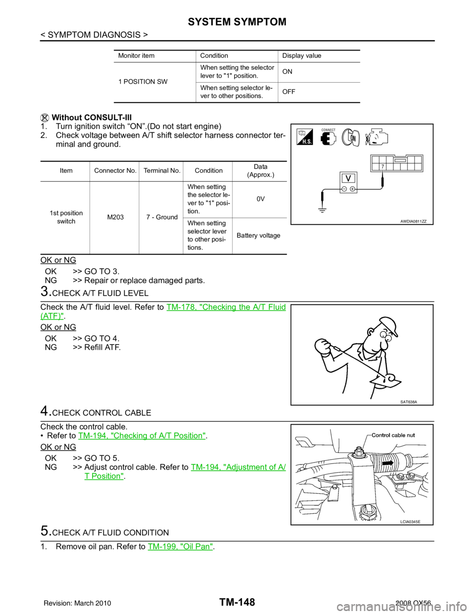
Without CONSULT-III
1. Turn ignition switch “ON”.(Do not start engine)
2. Check voltage between A/T shift selector harness connector ter-
minal and ground.
OK or NG
OK >> GO TO 3.
NG >> Repair or replace damaged parts.
3.CHECK A/T FLUID LEVEL
Check the A/T fluid level. Refer to TM-178, "
Checking the A/T Fluid
(ATF)".
OK or NG
OK >> GO TO 4.
NG >> Refill ATF.
4.CHECK CONTROL CABLE
Check the control cable.
• Refer to TM-194, "
Checking of A/T Position".
OK or NG
OK >> GO TO 5.
NG >> Adjust control cable. Refer to TM-194, "
Adjustment of A/
T Position".
5.CHECK A/T FLUID CONDITION
1. Remove oil pan. Refer to TM-199, "
Oil Pan".
Monitor itemConditionDisplay value
1 POSITION SW When setting the selector
lever to "1" position.
ON
When setting selector le-
ver to other positions. OFF
Item Connector No. Terminal No. Condition Data
(Approx.)
1st position switch M203 7 - Ground When setting
the selector le-
ver to "1" posi-
tion.
0V
When setting
selector lever
to other posi-
tions. Battery voltage
AWDIA0811ZZ
SAT638A
LCIA0345E
Revision: March 2010
2008 QX56
Page 3696 of 4083
SYSTEM SYMPTOMTM-149
< SYMPTOM DIAGNOSIS >
CEF
G H
I
J
K L
M A
B
TM
N
O P
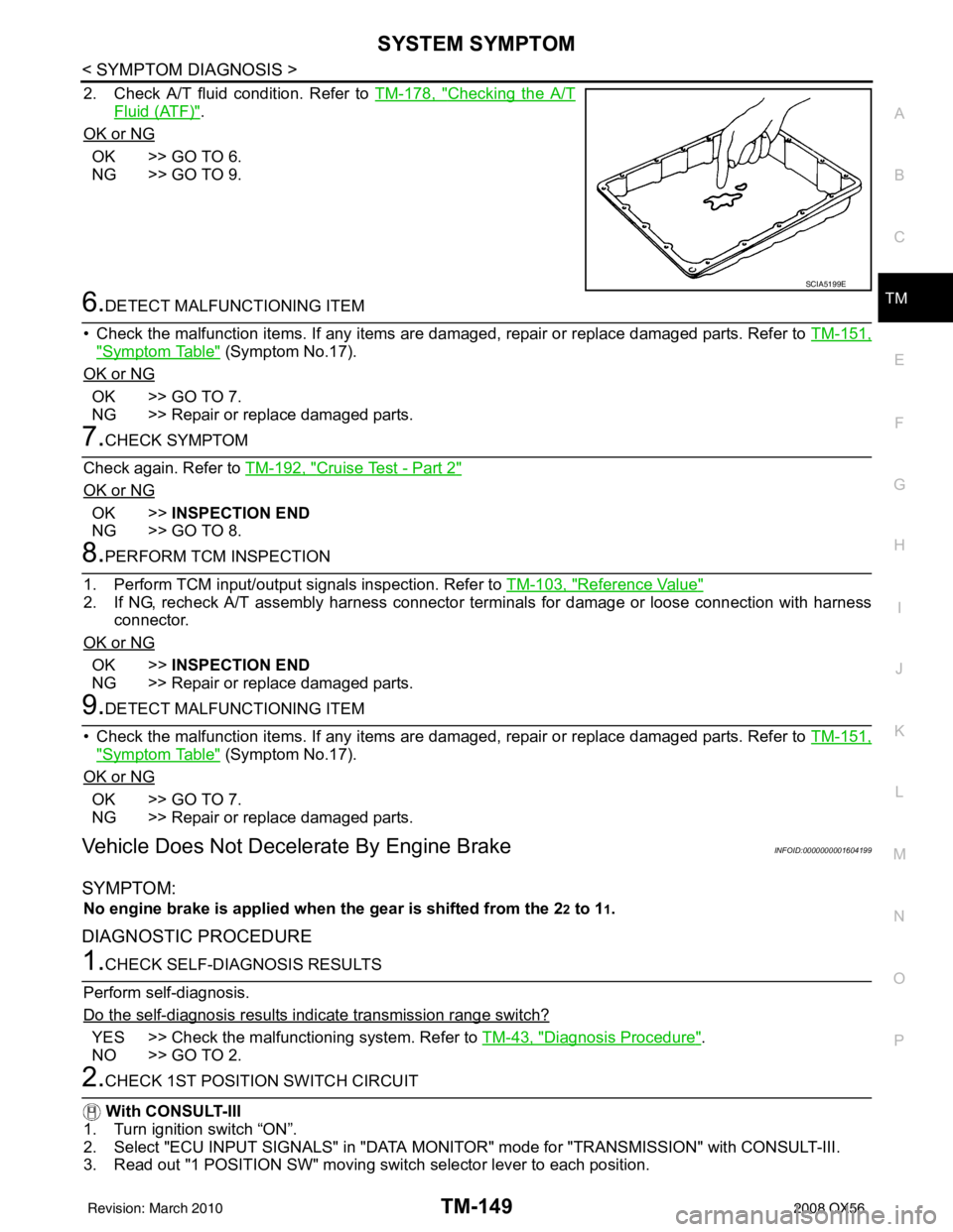
2. Check A/T fluid condition. Refer to TM-178, "Checking the A/T
Fluid (ATF)".
OK or NG
OK >> GO TO 6.
NG >> GO TO 9.
6.DETECT MALFUNCTIONING ITEM
• Check the malfunction items. If any items are damaged, repair or replace damaged parts. Refer to TM-151,
"Symptom Table" (Symptom No.17).
OK or NG
OK >> GO TO 7.
NG >> Repair or replace damaged parts.
7.CHECK SYMPTOM
Check again. Refer to TM-192, "
Cruise Test - Part 2"
OK or NG
OK >>INSPECTION END
NG >> GO TO 8.
8.PERFORM TCM INSPECTION
1. Perform TCM input/output signals inspection. Refer to TM-103, "
Reference Value"
2. If NG, recheck A/T assembly harness connector terminals for damage or loose connection with harness
connector.
OK or NG
OK >> INSPECTION END
NG >> Repair or replace damaged parts.
9.DETECT MALFUNCTIONING ITEM
• Check the malfunction items. If any items are damaged, repair or replace damaged parts. Refer to TM-151,
"Symptom Table" (Symptom No.17).
OK or NG
OK >> GO TO 7.
NG >> Repair or replace damaged parts.
Vehicle Does Not Decelerate By Engine BrakeINFOID:0000000001604199
SYMPTOM:
No engine brake is applied when the gear is shifted from the 22 to 11.
DIAGNOSTIC PROCEDURE
1.CHECK SELF-DIAGNOSIS RESULTS
Perform self-diagnosis.
Do the self-diagnosis results i ndicate transmission range switch?
YES >> Check the malfunctioning system. Refer to TM-43, "Diagnosis Procedure".
NO >> GO TO 2.
2.CHECK 1ST POSITION SWITCH CIRCUIT
With CONSULT-III
1. Turn ignition switch “ON”.
2. Select "ECU INPUT SIGNALS" in "DATA MONITO R" mode for "TRANSMISSION" with CONSULT-III.
3. Read out "1 POSITION SW" moving switch selector lever to each position.
SCIA5199E
Revision: March 2010 2008 QX56
Page 3697 of 4083
TM-150
< SYMPTOM DIAGNOSIS >
SYSTEM SYMPTOM
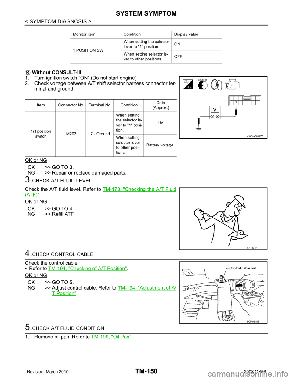
Without CONSULT-III
1. Turn ignition switch “ON”.(Do not start engine)
2. Check voltage between A/T shift selector harness connector ter-
minal and ground.
OK or NG
OK >> GO TO 3.
NG >> Repair or replace damaged parts.
3.CHECK A/T FLUID LEVEL
Check the A/T fluid level. Refer to TM-178, "
Checking the A/T Fluid
(ATF)".
OK or NG
OK >> GO TO 4.
NG >> Refill ATF.
4.CHECK CONTROL CABLE
Check the control cable.
• Refer to TM-194, "
Checking of A/T Position".
OK or NG
OK >> GO TO 5.
NG >> Adjust control cable. Refer to TM-194, "
Adjustment of A/
T Position".
5.CHECK A/T FLUID CONDITION
1. Remove oil pan. Refer to TM-199, "
Oil Pan".
Monitor itemConditionDisplay value
1 POSITION SW When setting the selector
lever to "1" position.
ON
When setting selector le-
ver to other positions. OFF
Item Connector No. Terminal No. Condition Data
(Approx.)
1st position switch M203 7 - Ground When setting
the selector le-
ver to "1" posi-
tion.
0V
When setting
selector lever
to other posi-
tions. Battery voltage
AWDIA0811ZZ
SAT638A
LCIA0345E
Revision: March 2010
2008 QX56