2008 INFINITI QX56 clutch
[x] Cancel search: clutchPage 3574 of 4083

A/T CONTROL SYSTEMTM-27
< FUNCTION DIAGNOSIS >
CEF
G H
I
J
K L
M A
B
TM
N
O P
FUNCTION OF PRESSURE SWITCH
Pilot valve A Adjusts the line pressure and produces the constant pressure (pilot pressure) required
for line pressure control, shift change control, and lock-up control.
Pilot valve B Adjusts the line pressure and produces the constant pressure (pilot pressure) required
for shift change control.
Low coast brake switching valve During engine braking, supplies the line pressure to the low coast brake reducing valve.
Low coast brake reducing valve When the low coast brake is coupled, adjusts the line pressure to the optimum pressure
(low coast brake pressure) and supplies it to the low coast brake.
N-R accumulator Produces the stabilizing pressure for when N-R is selected.
Direct clutch piston switching valve Operates in 4GR gear and switches the direct clutch coupling capacity.
High and low reverse clutch control valve When the high and low reverse clutch is coupled, adjusts the line pressure to the opti-
mum pressure (high and low reverse clutch pressure) and supplies it to the high and low
reverse clutch. (In 1GR, 3GR, 4GR and 5GR, adjusts the clutch pressure.)
Input clutch control valve When the input clutch is coupled, adjusts the line pressure to the optimum pressure (in-
put clutch pressure) and supplies it to the input clutch. (In 4GR and 5GR, adjusts the
clutch pressure.)
Direct clutch control valve When the direct clutch is coupled, adjusts the line pressure to the optimum pressure (di-
rect clutch pressure) and supplies it to the direct clutch. (In 2GR, 3GR, and 4GR, adjusts
the clutch pressure.)
TCC control valve
TCC control plug
TCC control sleeve Switches the lock-up to operating or released. Also, by performing the lock-up operation
transiently, lock-up smoothly.
Torque converter lubrication valve Operates during lock-up to switch the torque converter, cooling, and lubrication system
oil path.
Cool bypass valve Allows excess oil to bypass cooler circuit without being fed into it.
Line pressure relief valve Discharges excess oil from line pressure circuit.
N-D accumulator Produces the stabilizing pressure for when N-D is selected.
Manual valve Sends line pressure to each circuit according to the select position. The circuits to which
the line pressure is not sent drain.
Name
Function
Name Function
Pressure switch 2 (LC/B) Detects any malfunction in the low coast brake hydraulic pressure. When it detects any
malfunction, it puts the system into fail-safe mode.
Revision: March 2010
2008 QX56
Page 3580 of 4083
DIAGNOSIS SYSTEM (TCM)TM-33
< FUNCTION DIAGNOSIS >
CEF
G H
I
J
K L
M A
B
TM
N
O P
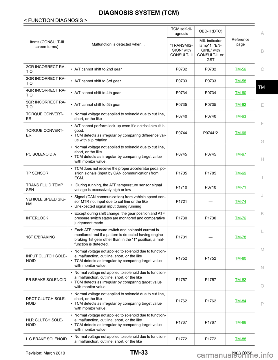
2GR INCORRECT RA-
TIO • A/T cannot shift to 2nd gear
P0732 P0732TM-56
3GR INCORRECT RA-
TIO• A/T cannot shift to 3rd gear
P0733 P0733TM-58
4GR INCORRECT RA-
TIO• A/T cannot shift to 4th gear
P0734 P0734TM-60
5GR INCORRECT RA-
TIO• A/T cannot shift to 5th gear
P0735 P0735TM-62
TORQUE CONVERT-
ER• Normal voltage not applied to solenoid due to cut line,
short, or the like P0740 P0740
TM-63
TORQUE CONVERT-
ER• A/T cannot perform lock-up even if electrical circuit is
good.
• TCM detects as irregular by comparing difference val- ue with slip rotation. P0744 P0744*2
TM-66
PC SOLENOID A• Normal voltage not applied to solenoid due to cut line,
short, or the like
• TCM detects as irregular by comparing target value with monitor value. P0745 P0745
TM-67
TP SENSOR• TCM does not receive the proper accelerator pedal po-
sition signals (input by CAN communication) from
ECM. P1705 P1705
TM-69
TRANS FLUID TEMP
SEN• During running, the ATF temperature sensor signal
voltage is excessively high or low P1710 P0710
TM-71
VEHICLE SPEED SIG-
NAL• Signal (CAN communication) from vehicle speed sen-
sor MTR not input due to cut line or the like
• Unexpected signal input during running P1721
—TM-74
INTERLOCK • Except during shift change, the gear position and ATF
pressure switch states are monitored and comparative
judgement made. P1730 P1730
TM-76
1ST E/BRAKING• Each ATF pressure switch and solenoid current is
monitored and if a pattern is detected having engine
braking 1st gear other than in the "1" position, a mal-
function is detected. P1731
—TM-78
INPUT CLUTCH SOLE-
NOID • Normal voltage not applied to solenoid due to function-
al malfunction, cut line, short, or the like
• TCM detects as irregular by comparing target value with monitor value. P1752 P1752
TM-80
FR BRAKE SOLENOID• Normal voltage not applied to solenoid due to function-
al malfunction, cut line, short, or the like
• TCM detects as irregular by comparing target value with monitor value. P1757 P1757
TM-82
DRCT CLUTCH SOLE-
NOID• Normal voltage not applied to solenoid due to cut line,
short, or the like
• TCM detects as irregular by comparing target value with monitor value. P1762 P1762
TM-84
HLR CLUTCH SOLE-
NOID• Normal voltage not applied to solenoid due to function-
al malfunction, cut line, short, or the like
• TCM detects as irregular by comparing target value with monitor value. P1767 P1767
TM-86
L C BRAKE SOLENOID• Normal voltage not applied to solenoid due to function-
al malfunction, cut line, short, or the like P1772 P1772
TM-88
Items (CONSULT-III
screen terms) Malfunction is detected when... TCM self-di-
agnosis OBD-II (DTC)
Reference page
“TRANSMIS-
SION” with
CONSULT-III MIL indicator
lamp*1, “EN-
GINE” with
CONSULT-III or
GST
Revision: March 2010 2008 QX56
Page 3584 of 4083

DIAGNOSIS SYSTEM (TCM)TM-37
< FUNCTION DIAGNOSIS >
CEF
G H
I
J
K L
M A
B
TM
N
O P
DTC WORK SUPPORT MODE
Display Items List
Frequency (Hz) —— X
The value measured by the pulse probe is dis-
played.
DUTY-HI (high) (%)
—— X
DUTY-LOW (low) (%) —— X
PLS WIDTH-HI (ms) —— X
PLS WIDTH-LOW (ms) —— X
Monitored item (Unit)
Monitor Item Selection
Remarks
ECU IN-
PUT SIG- NALS MAIN SIG-
NALS SELEC-
TION
FROM
MENU
DTC work support item DescriptionCheck item
1ST GR FUNCTN P0731 Following items for “” be confirmed.
• Self-diagnosis status (whether the diagnosis is being performed
or not)
• Self-diagnosis result (OK or NG)
• Input clutch solenoid valve
• Front brake solenoid valve
• Direct clutch solenoid valve
• High and low reverse clutch solenoid valve
• Each clutch
• Hydraulic co ntrol circuit
valve
2ND GR FUNCTN P0732
Following items for “” be confirmed.
• Self-diagnosis status (whether the diagnosis is being performed
or not)
• Self-diagnosis result (OK or NG)
3RD GR FUNCTN P0733 Following items for “” be confirmed.
• Self-diagnosis status (whether the diagnosis is being performed
or not)
• Self-diagnosis result (OK or NG)
4TH GR FUNCTN P0734 Following items for “” be confirmed.
• Self-diagnosis status (whether the diagnosis is being performed
or not)
• Self-diagnosis result (OK or NG)
5TH GR FUNCTN P0735 Following items for “” be confirmed.
• Self-diagnosis status (whether the diagnosis is being performed
or not)
• Self-diagnosis result (OK or NG)
Revision: March 2010 2008 QX56
Page 3600 of 4083
P0731 1GR INCORRECT RATIOTM-53
< COMPONENT DIAGNOSIS >
CEF
G H
I
J
K L
M A
B
TM
N
O P
P0731 1GR INCORRECT RATIO
DescriptionINFOID:0000000001604050
This malfunction is detected when the A/T does not shift into 1GR position as instructed by TCM. This is not
only caused by electrical malfunction (circuits open or shorted) but also by mechanical malfunction such as
control valve sticking, improper solenoid valve operation.
On Board Diagnosis LogicINFOID:0000000001604051
• This is an OBD-II self-diagnostic item.
• Diagnostic trouble code “P0731” is detected when TCM detec ts any inconsistency in the actual gear ratio.
Possible CauseINFOID:0000000001604052
• Harness or connectors
(Solenoid circuits are open or shorted.)
• Input clutch solenoid valve
• Front brake solenoid valve
• Direct clutch solenoid valve
• High and low reverse clutch solenoid valve
• Each clutch
• Hydraulic control circuit
DTC Confirmation ProcedureINFOID:0000000001604053
CAUTION:
Always drive vehicle at a safe speed.
NOTE:
If “DTC Confirmation Procedure” has been previously performed, always turn ignition switch OFF and
wait at least 10 seconds before performing the next test.
After the repair, perform the following procedure to confirm the malfunction is eliminated.
WITH CONSULT-III
1. Start the engine and select “DATA MONITOR” mode for “TRANSMISSION” with CONSULT-III.
2. Make sure that “ATF TEMP 1” is within the following range. ATF TEMP 1: 20 °C – 140 °C
If out of range, drive vehicle to warm ATF or stop engine to cool ATF.
3. Select “1ST GR FNCTN P0731” of “DTC WO RK SUPPORT” mode for “TRANSMISSION” with CON-
SULT-III.
4. Drive vehicle and maintain the following conditions.
VEHICLE SPEED: 10 km/h (6 MPH) or more
ACCELE POSI: 0.6/8 or more
ENGINE SPEED: INPUT SPEED − 50 rpm or more
INPUT SPEED: 300 rpm or more
GEAR: “1” position
MANU MODE SW: ON
5. Keep the current driving status for at least 5 consecutive seconds if CONSULT-III screen changes from “OUT OF CONDITION” to “TESTING”.
CAUTION:
If “TESTING” does not appear on CONSULT-III for a long time, select “SELF-DIAG RESULTS”. In
case a 1st trip DTC other than P0731 is shown, refer to “ TM-116, "
DTC No. Index"”.
If “COMPLETED RESULT NG” is detected, go to TM-54, "
Diagnosis Procedure".
If “STOP VEHICLE” is detec ted, go to the following step.
6. Stop vehicle.
7. Drive vehicle in “D” position allowing it to shift from 1GR to 5GR and check shift timing and shift shock.
- Touch “OK” to complete the inspection when normally shifted from the 1GR to 5GR.
- Touch “NG” when an unusual shift shock, etc. occurs in spite of shifting from the 1GR to 5GR. Go to TM-
189, "Description".
-Perform TM-32, "
CONSULT-III Functi on (TRANSMISSION)" when not shifted from the 1GR to 5GR. (Nei-
ther “OK” nor “NG” are indicated.)
Revision: March 2010 2008 QX56
Page 3602 of 4083
P0732 2GR INCORRECT RATIOTM-55
< COMPONENT DIAGNOSIS >
CEF
G H
I
J
K L
M A
B
TM
N
O P
P0732 2GR INCORRECT RATIO
DescriptionINFOID:0000000001604055
This malfunction is detected when the A/T does not shift into 2GR position as instructed by TCM. This is not
only caused by electrical malfunction (circuits open or shorted) but also by mechanical malfunction such as
control valve sticking, improper solenoid valve operation.
On Board Diagnosis LogicINFOID:0000000001604056
• This is an OBD-II self-diagnostic item.
• Diagnostic trouble code “P0732” detected when TCM detects any inconsistency in the actual gear ratio.
Possible CauseINFOID:0000000001604057
• Harness or connectors (Solenoid circuits are open or shorted.)
• Input clutch solenoid valve
• Front brake solenoid valve
• Direct clutch solenoid valve
• High and low reverse clutch solenoid valve
• Each clutch
• Hydraulic control circuit
DTC Confirmation ProcedureINFOID:0000000001604058
CAUTION:
Always drive vehicle at a safe speed.
NOTE:
If “DTC Confirmation Procedure” has been previously performed, always turn ignition switch OFF and
wait at least 10 seconds before performing the next test.
After the repair, perform the following procedure to confirm the malfunction is eliminated.
WITH CONSULT-III
1. Start the engine and select “DATA MONITOR” mode for “TRANSMISSION” with CONSULT-III.
2. Make sure that “ATF TEMP 1” is within the following range. ATF TEMP 1: 20 °C – 140 °C
If out of range, drive vehicle to warm ATF or stop engine to cool ATF.
3. Select “2ND GR FNCTN P0732” of “DTC WORK SUPPORT” mode for “TRANSMISSION” with CON-
SULT-III.
4. Drive vehicle and maintain the following conditions.
VEHICLE SPEED: 10 km/h (6 MPH) or more
ACCELE POSI: 0.6/8 or more
ENGINE SPEED: INPUT SPEED − 50 rpm or more
INPUT SPEED: 300 rpm or more
GEAR: “2” position
MANU MODE SW: ON
5. Keep the current driving status for at least 5 consecutive seconds if CONSULT-III screen changes from “OUT OF CONDITION” to “TESTING”.
CAUTION:
If “TESTING” does not appear on CONSULT-III for a long time, select “SELF-DIAG RESULTS”. In
case a 1st trip DTC other than P0732 is shown, refer to “ TM-116, "
DTC No. Index"”.
If “COMPLETED RESULT NG” is detected, go to TM-56, "
Diagnosis Procedure".
If “STOP VEHICLE” is detec ted, go to the following step.
6. Stop vehicle.
7. Drive vehicle in “D” position allowing it to shift from 1st to 5GR and check shift timing and shift shock.
- Touch “OK” to complete the inspection when normally shifted from the 1GR to 5GR.
- Touch “NG” when an unusual shift shock, etc. occurs in spite of shifting from the 1GR to 5GR. Go to TM-
189, "Description".
-Perform TM-32, "
CONSULT-III Functi on (TRANSMISSION)" when not shifted from the 1GR to 5GR. (Nei-
ther “OK” nor “NG” are indicated.)
Revision: March 2010 2008 QX56
Page 3604 of 4083
P0733 3GR INCORRECT RATIOTM-57
< COMPONENT DIAGNOSIS >
CEF
G H
I
J
K L
M A
B
TM
N
O P
P0733 3GR INCORRECT RATIO
DescriptionINFOID:0000000001604060
This malfunction is detected when the A/T does not shift into 3GR position as instructed by TCM. This is not
only caused by electrical malfunction (circuits open or shorted) but also by mechanical malfunction such as
control valve sticking, improper solenoid valve operation.
On Board Diagnosis LogicINFOID:0000000001604061
• This is an OBD-II self-diagnostic item.
• Diagnostic trouble code “P0733” is detected when TCM detec ts any inconsistency in the actual gear ratio.
Possible CauseINFOID:0000000001604062
• Harness or connectors
(Solenoid circuits are open or shorted.)
• Input clutch solenoid valve
• Front brake solenoid valve
• Direct clutch solenoid valve
• High and low reverse clutch solenoid valve
• Each clutch
• Hydraulic control circuit
DTC Confirmation ProcedureINFOID:0000000001604063
CAUTION:
Always drive vehicle at a safe speed.
NOTE:
If “DTC Confirmation Procedure” has been previously performed, always turn ignition switch OFF and
wait at least 10 seconds before performing the next test.
After the repair, perform the following procedure to confirm the malfunction is eliminated.
WITH CONSULT-III
1. Start the engine and select “DATA MONITOR” mode for “TRANSMISSION” with CONSULT-III.
2. Make sure that “ATF TEMP 1” is within the following range. ATF TEMP 1: 20 °C – 140 °C
If out of range, drive vehicle to warm ATF or stop engine to cool ATF.
3. Select “3RD GR FNCTN P0733” of “DTC WORK SUPPORT” mode for “TRANSMISSION” with CON-
SULT-III.
4. Drive vehicle and maintain the following conditions.
VEHICLE SPEED: 10 km/h (6 MPH) or more
ACCELE POSI: 0.6/8 or more
ENGINE SPEED: INPUT SPEED − 50 rpm or more
INPUT SPEED: 300 rpm or more
GEAR: “3” position
MANU MODE SW: ON
5. Keep the current driving status for at least 5 consecutive seconds if CONSULT-III screen changes from “OUT OF CONDITION” to “TESTING”.
CAUTION:
If “TESTING” does not appear on CONSULT-III for a long time, select “SELF-DIAG RESULTS”. In
case a 1st trip DTC other than P0732 is shown, refer to “ TM-116, "
DTC No. Index"”.
If “COMPLETED RESULT NG” is detected, go to TM-58, "
Diagnosis Procedure".
If “STOP VEHICLE” is detec ted, go to the following step.
6. Stop vehicle.
7. Drive vehicle in “D” position allowing it to shift from 1GR to 5GR and check shift timing and shift shock.
- Touch “OK” to complete the inspection when normally shifted from the 1GR to 5GR.
- Touch “NG” when an unusual shift shock, etc. occurs in spite of shifting from the 1GR to 5GR. Go to TM-
189, "Description".
-Perform TM-32, "
CONSULT-III Functi on (TRANSMISSION)" when not shifted from the 1GR to 5GR. (Nei-
ther “OK” nor “NG” are indicated.)
Revision: March 2010 2008 QX56
Page 3606 of 4083
P0734 4GR INCORRECT RATIOTM-59
< COMPONENT DIAGNOSIS >
CEF
G H
I
J
K L
M A
B
TM
N
O P
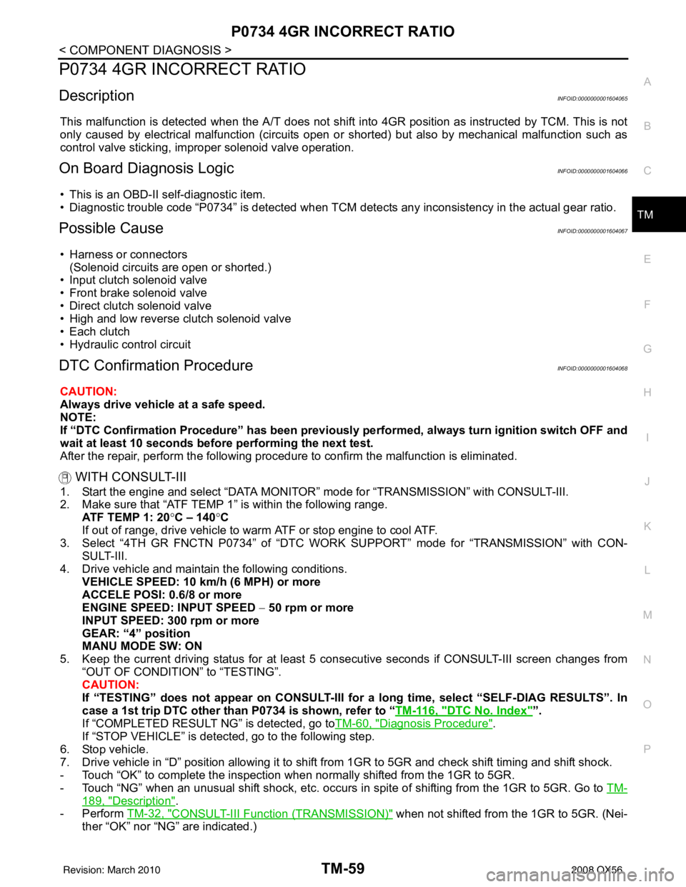
P0734 4GR INCORRECT RATIO
DescriptionINFOID:0000000001604065
This malfunction is detected when the A/T does not shift into 4GR position as instructed by TCM. This is not
only caused by electrical malfunction (circuits open or shorted) but also by mechanical malfunction such as
control valve sticking, improper solenoid valve operation.
On Board Diagnosis LogicINFOID:0000000001604066
• This is an OBD-II self-diagnostic item.
• Diagnostic trouble code “P0734” is detected when TCM detec ts any inconsistency in the actual gear ratio.
Possible CauseINFOID:0000000001604067
• Harness or connectors
(Solenoid circuits are open or shorted.)
• Input clutch solenoid valve
• Front brake solenoid valve
• Direct clutch solenoid valve
• High and low reverse clutch solenoid valve
• Each clutch
• Hydraulic control circuit
DTC Confirmation ProcedureINFOID:0000000001604068
CAUTION:
Always drive vehicle at a safe speed.
NOTE:
If “DTC Confirmation Procedure” has been previously performed, always turn ignition switch OFF and
wait at least 10 seconds before performing the next test.
After the repair, perform the following procedure to confirm the malfunction is eliminated.
WITH CONSULT-III
1. Start the engine and select “DATA MONITOR” mode for “TRANSMISSION” with CONSULT-III.
2. Make sure that “ATF TEMP 1” is within the following range. ATF TEMP 1: 20 °C – 140 °C
If out of range, drive vehicle to warm ATF or stop engine to cool ATF.
3. Select “4TH GR FNCTN P0734” of “DTC WORK SUPPORT” mode for “TRANSMISSION” with CON-
SULT-III.
4. Drive vehicle and maintain the following conditions.
VEHICLE SPEED: 10 km/h (6 MPH) or more
ACCELE POSI: 0.6/8 or more
ENGINE SPEED: INPUT SPEED − 50 rpm or more
INPUT SPEED: 300 rpm or more
GEAR: “4” position
MANU MODE SW: ON
5. Keep the current driving status for at least 5 consecutive seconds if CONSULT-III screen changes from “OUT OF CONDITION” to “TESTING”.
CAUTION:
If “TESTING” does not appear on CONSULT-III for a long time, select “SELF-DIAG RESULTS”. In
case a 1st trip DTC other than P0734 is shown, refer to “ TM-116, "
DTC No. Index"”.
If “COMPLETED RESULT NG” is detected, go toTM-60, "
Diagnosis Procedure".
If “STOP VEHICLE” is detec ted, go to the following step.
6. Stop vehicle.
7. Drive vehicle in “D” position allowing it to shift from 1GR to 5GR and check shift timing and shift shock.
- Touch “OK” to complete the inspection when normally shifted from the 1GR to 5GR.
- Touch “NG” when an unusual shift shock, etc. occurs in spite of shifting from the 1GR to 5GR. Go to TM-
189, "Description".
-Perform TM-32, "
CONSULT-III Functi on (TRANSMISSION)" when not shifted from the 1GR to 5GR. (Nei-
ther “OK” nor “NG” are indicated.)
Revision: March 2010 2008 QX56
Page 3608 of 4083
P0735 5GR INCORRECT RATIOTM-61
< COMPONENT DIAGNOSIS >
CEF
G H
I
J
K L
M A
B
TM
N
O P
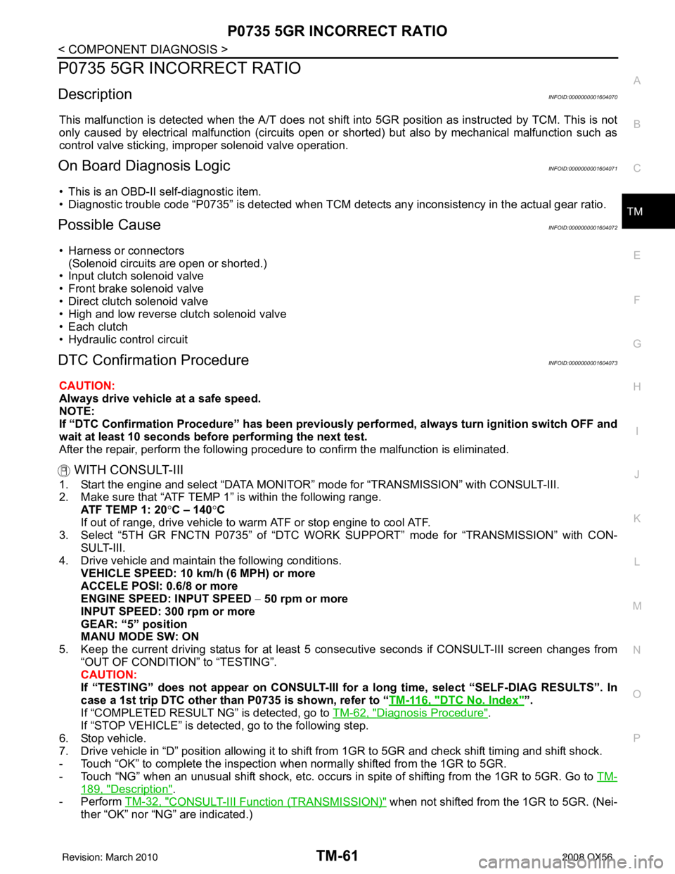
P0735 5GR INCORRECT RATIO
DescriptionINFOID:0000000001604070
This malfunction is detected when the A/T does not shift into 5GR position as instructed by TCM. This is not
only caused by electrical malfunction (circuits open or shorted) but also by mechanical malfunction such as
control valve sticking, improper solenoid valve operation.
On Board Diagnosis LogicINFOID:0000000001604071
• This is an OBD-II self-diagnostic item.
• Diagnostic trouble code “P0735” is detected when TCM detec ts any inconsistency in the actual gear ratio.
Possible CauseINFOID:0000000001604072
• Harness or connectors
(Solenoid circuits are open or shorted.)
• Input clutch solenoid valve
• Front brake solenoid valve
• Direct clutch solenoid valve
• High and low reverse clutch solenoid valve
• Each clutch
• Hydraulic control circuit
DTC Confirmation ProcedureINFOID:0000000001604073
CAUTION:
Always drive vehicle at a safe speed.
NOTE:
If “DTC Confirmation Procedure” has been previously performed, always turn ignition switch OFF and
wait at least 10 seconds before performing the next test.
After the repair, perform the following procedure to confirm the malfunction is eliminated.
WITH CONSULT-III
1. Start the engine and select “DATA MONITOR” mode for “TRANSMISSION” with CONSULT-III.
2. Make sure that “ATF TEMP 1” is within the following range. ATF TEMP 1: 20 °C – 140 °C
If out of range, drive vehicle to warm ATF or stop engine to cool ATF.
3. Select “5TH GR FNCTN P0735” of “DTC WORK SUPPORT” mode for “TRANSMISSION” with CON-
SULT-III.
4. Drive vehicle and maintain the following conditions.
VEHICLE SPEED: 10 km/h (6 MPH) or more
ACCELE POSI: 0.6/8 or more
ENGINE SPEED: INPUT SPEED − 50 rpm or more
INPUT SPEED: 300 rpm or more
GEAR: “5” position
MANU MODE SW: ON
5. Keep the current driving status for at least 5 consecutive seconds if CONSULT-III screen changes from “OUT OF CONDITION” to “TESTING”.
CAUTION:
If “TESTING” does not appear on CONSULT-III for a long time, select “SELF-DIAG RESULTS”. In
case a 1st trip DTC other than P0735 is shown, refer to “ TM-116, "
DTC No. Index"”.
If “COMPLETED RESULT NG” is detected, go to TM-62, "
Diagnosis Procedure".
If “STOP VEHICLE” is detec ted, go to the following step.
6. Stop vehicle.
7. Drive vehicle in “D” position allowing it to shift from 1GR to 5GR and check shift timing and shift shock.
- Touch “OK” to complete the inspection when normally shifted from the 1GR to 5GR.
- Touch “NG” when an unusual shift shock, etc. occurs in spite of shifting from the 1GR to 5GR. Go to TM-
189, "Description".
-Perform TM-32, "
CONSULT-III Functi on (TRANSMISSION)" when not shifted from the 1GR to 5GR. (Nei-
ther “OK” nor “NG” are indicated.)
Revision: March 2010 2008 QX56