2008 INFINITI QX56 ignition
[x] Cancel search: ignitionPage 3100 of 4083
POWER SUPPLY AND GROUND CIRCUITSCS-17
< COMPONENT DIAGNOSIS >
C
DF
G H
I
J
K L
M A
B
SCS
N
O P
POWER SUPPLY AND GROUND CIRCUIT
SUSPENSION CONTROL UNIT
SUSPENSION CONTROL UNIT : Diagnosis ProcedureINFOID:0000000001731984
1.CHECK FUSES
Check that the following fuses of the sus pension control unit are not are not blown.
Are the fuses OK?
YES >> GO TO 2
NO >> If fuse is blown, be sure to eliminate cause of malfunction before installing new fuse.
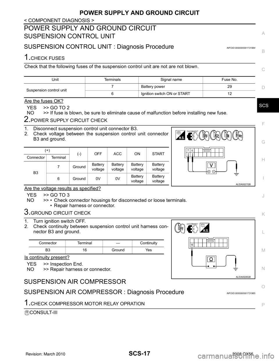
2.POWER SUPPLY CIRCUIT CHECK
1. Disconnect suspension control unit connector B3.
2. Check voltage between the suspension control unit connector B3 and ground.
Are the voltage results as specified?
YES >> GO TO 3
NO >> • Check connector housings for disconnected or loose terminals. • Repair harness or connector.
3.GROUND CIRCUIT CHECK
1. Turn ignition switch OFF.
2. Check continuity between suspension control unit harness con- nector B3 and ground.
Is continuity present?
YES >> Inspection End.
NO >> Repair harness or connector.
SUSPENSION AIR COMPRESSOR
SUSPENSION AIR COMPRESSOR : Diagnosis ProcedureINFOID:0000000001731985
1.CHECK COMPRESSOR MOTOR RELAY OPRATION
CONSULT-III
Unit Terminals Signal name Fuse No.
Suspension control unit 7
Battery power 29
6 Ignition switch ON or START 12
(+)
(-) OFF ACC ON START
Connector Terminal
B3 7Ground
Battery
voltage Battery
voltage Battery
voltage Battery
voltage
6Ground0V 0V Battery
voltage Battery
voltage
ALEIA0027GB
Connector Terminal —Continuity
B3 16Ground Yes
ALEIA0028GB
Revision: March 2010 2008 QX56
Page 3101 of 4083
SCS-18
< COMPONENT DIAGNOSIS >
POWER SUPPLY AND GROUND CIRCUIT
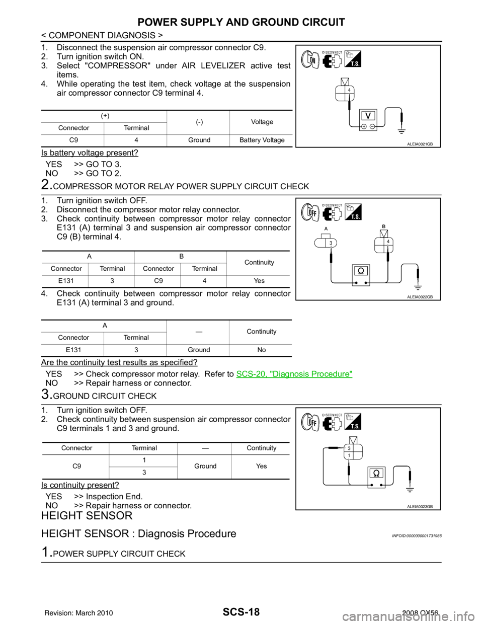
1. Disconnect the suspension air compressor connector C9.
2. Turn ignition switch ON.
3. Select "COMPRESSOR" under AIR LEVELIZER active testitems.
4. While operating the test item, check voltage at the suspension
air compressor connector C9 terminal 4.
Is battery voltage present?
YES >> GO TO 3.
NO >> GO TO 2.
2.COMPRESSOR MOTOR RELAY POWER SUPPLY CIRCUIT CHECK
1. Turn ignition switch OFF.
2. Disconnect the compressor motor relay connector.
3. Check continuity between compressor motor relay connector E131 (A) terminal 3 and suspension air compressor connector
C9 (B) terminal 4.
4. Check continuity between compressor motor relay connector E131 (A) terminal 3 and ground.
Are the continuity test results as specified?
YES >> Check compressor motor relay. Refer to SCS-20, "Diagnosis Procedure"
NO >> Repair harness or connector.
3.GROUND CIRCUIT CHECK
1. Turn ignition switch OFF.
2. Check continuity between suspension air compressor connector C9 terminals 1 and 3 and ground.
Is continuity present?
YES >> Inspection End.
NO >> Repair harness or connector.
HEIGHT SENSOR
HEIGHT SENSOR : Dia gnosis ProcedureINFOID:0000000001731986
1.POWER SUPPLY CIRCUIT CHECK
(+)
(-)Voltage
Connector Terminal
C9 4Ground Battery Voltage
ALEIA0021GB
AB
Continuity
Connector Terminal Connector Terminal
E131 3 C9 4 Yes
A —Con tin uit y
Connector Terminal
E131 3Ground No
ALEIA0022GB
Connector Terminal —Continuity
C9 1
Ground Yes
3
ALEIA0023GB
Revision: March 2010 2008 QX56
Page 3102 of 4083

POWER SUPPLY AND GROUND CIRCUITSCS-19
< COMPONENT DIAGNOSIS >
C
DF
G H
I
J
K L
M A
B
SCS
N
O P
1. Disconnect height sensor connector C8.
2. Turn the ignition switch ON.
3. Check voltage between the height sensor connector C8 terminal 1 and ground.
Is 5V present?
YES >> GO TO 2
NO >> Check harness or connector for open or short. If OK, replace the suspension control unit. Refer to RSU-25, "
Removal and Installation"
2.GROUND CIRCUIT CHECK
1. Turn ignition switch OFF.
2. Check continuity between height sensor connector C8 terminal 3 and ground.
Is continuity present?
YES >> Ground circuit is OK.
NO >> Repair harness or connector.
(+) (-) Voltage
Connector Terminal
C8 1 Ground 5V
ALEIA0026GB
Connector Terminal —Continuity
C8 3Ground Yes
ALEIA0029GB
Revision: March 2010 2008 QX56
Page 3103 of 4083
SCS-20
< COMPONENT DIAGNOSIS >
COMPRESSOR MOTOR RELAY
COMPRESSOR MOTOR RELAY
DescriptionINFOID:0000000001731987
Receives suspension air compressor ON signal from suspension control unit. When activated, the compressor
motor relay supplies power to the suspension air compressor.
Component Function CheckINFOID:0000000001731988
1.CHECK COMPRESSOR MOTOR RELAY OPERATION
CAUTION:
The "COMPRESSOR" active test will remain ON until it is turned off using CONSULT-III. Allowing the
compressor to run for an extended period of time may cause damage to the suspension control sys-
tem components due to excessive air pressure.
CONSULT-III
1. Turn ignition ON.
2. Select "COMPRESSOR" of AIR LEVELIZER active test items.
3. While operating test item, check that the suspension air compressor turns ON.
Does the suspension air compressor operate properly?
YES >> Compressor motor relay and suspension air compressor are operating normally.
NO >> Refer to SCS-20, "
Diagnosis Procedure"
Diagnosis ProcedureINFOID:0000000001731989
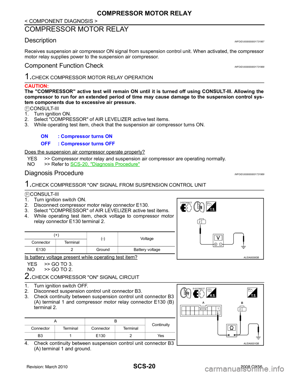
1.CHECK COMPRESSOR "ON" SIGNAL FROM SUSPENSION CONTROL UNIT
CONSULT-III
1. Turn ignition switch ON.
2. Disconnect compressor motor relay connector E130.
3. Select "COMPRESSOR" of AIR LEVELIZER active test items.
4. While operating test item, check voltage to compressor motor relay connector E130 terminal 2.
Is battery voltage present while operating test item?
YES >> GO TO 3.
NO >> GO TO 2.
2.CHECK COMPRESSOR "ON" SIGNAL CIRCUIT
1. Turn ignition switch OFF.
2. Disconnect suspension control unit connector B3.
3. Check continuity between suspension control unit connector B3 (A) terminal 1 and compressor motor relay connector E130 (B)
terminal 2.
4. Check continuity between suspension control unit connector B3 (A) terminal 1 and ground.ON : Compressor turns ON
OFF : Compressor turns OFF
(+)
(-)Voltage
Connector Terminal
E130 2Ground Battery voltage
ALEIA0030GB
AB
Continuity
Connector Terminal Connector Terminal
B3 1E 1302 Y es
ALEIA0031GB
Revision: March 2010 2008 QX56
Page 3104 of 4083
COMPRESSOR MOTOR RELAYSCS-21
< COMPONENT DIAGNOSIS >
C
DF
G H
I
J
K L
M A
B
SCS
N
O P
Are the continuity test results as specified?
YES >> Replace the suspension control unit. Refer to RSU-25, "Removal and Installation"
NO >> Repair harness or connector.
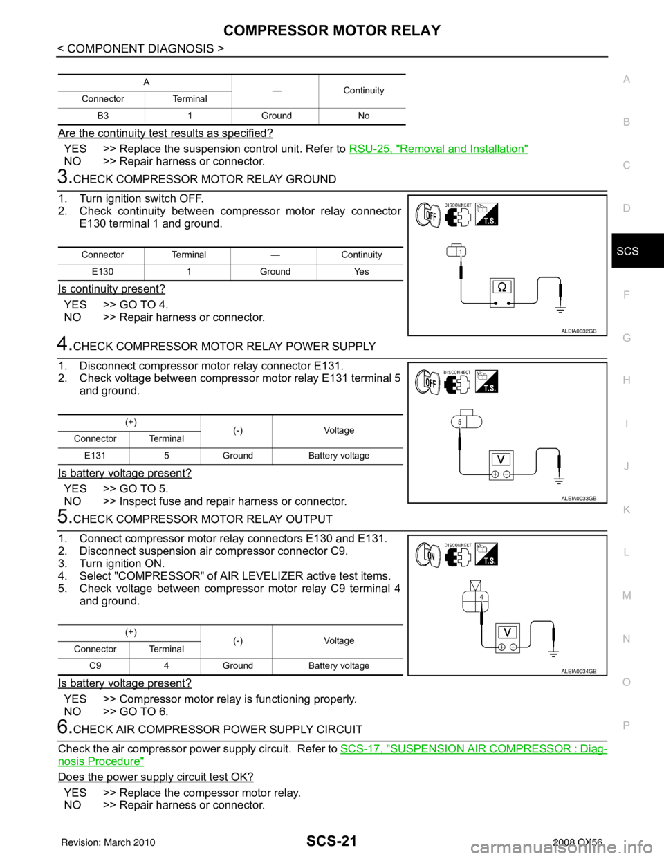
3.CHECK COMPRESSOR MOTOR RELAY GROUND
1. Turn ignition switch OFF.
2. Check continuity between compressor motor relay connector E130 terminal 1 and ground.
Is continuity present?
YES >> GO TO 4.
NO >> Repair harness or connector.
4.CHECK COMPRESSOR MOTOR RELAY POWER SUPPLY
1. Disconnect compressor motor relay connector E131.
2. Check voltage between compressor motor relay E131 terminal 5 and ground.
Is battery voltage present?
YES >> GO TO 5.
NO >> Inspect fuse and repair harness or connector.
5.CHECK COMPRESSOR MOTOR RELAY OUTPUT
1. Connect compressor motor relay connectors E130 and E131.
2. Disconnect suspension air compressor connector C9.
3. Turn ignition ON.
4. Select "COMPRESSOR" of AIR LEVELIZER active test items.
5. Check voltage between compressor motor relay C9 terminal 4 and ground.
Is battery voltage present?
YES >> Compressor motor relay is functioning properly.
NO >> GO TO 6.
6.CHECK AIR COMPRESSOR POWER SUPPLY CIRCUIT
Check the air compressor power supply circuit. Refer to SCS-17, "
SUSPENSION AIR COMPRESSOR : Diag-
nosis Procedure"
Does the power supply circuit test OK?
YES >> Replace the compessor motor relay.
NO >> Repair harness or connector.
A — Continuity
Connector Terminal
B3 1 Ground No
Connector Terminal —Continuity
E130 1Ground Yes
ALEIA0032GB
(+)
(-)Voltage
Connector Terminal
E131 5Ground Battery voltage
ALEIA0033GB
(+)
(-)Voltage
Connector Terminal
C9 4Ground Battery voltage
ALEIA0034GB
Revision: March 2010 2008 QX56
Page 3106 of 4083
EXHAUST VALVE SOLENOID CIRCUITSCS-23
< COMPONENT DIAGNOSIS >
C
DF
G H
I
J
K L
M A
B
SCS
N
O P
EXHAUST VALVE SOLENOID CIRCUIT
DescriptionINFOID:0000000001731993
Receives exhaust valve solenoid signal from suspension control unit. When activated, the exhaust valve sole-
noid releases air pressure from the suspension control system.
Component Function CheckINFOID:0000000001731994
1.CHECK EXHAUST SOLENOID OPERATION
CAUTION:
While operating this active test, the suspension control system wil l vent air pressure and the vehicle
ride height will lower. Ensure th e area around the vehicle is free from obstructions before beginning
test.
CONSULT-III
1. Ensure the suspension control system has air pressure and is not drooping in the rear.
2. Select "EXHAUST SOLENOID" of AIR LEVELIZER active test items.
3. While operating test item, check that the exhaust va lve solenoid opens to vent air from the system. The
vehicle should lower when the exhaust valve solenoid is activated.
Does the system vent properly?
YES >> Exhaust valve solenoid is operating normally.
NO >> Refer to SCS-23, "
Diagnosis Procedure"
Diagnosis ProcedureINFOID:0000000001731995
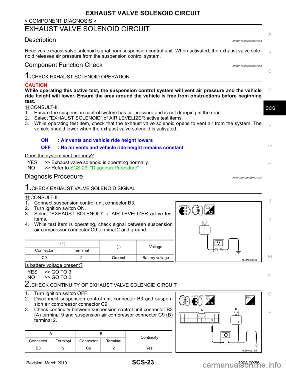
1.CHECK EXHAUST VALVE SOLENOID SIGNAL
CONSULT-III
1. Connect suspension control unit connector B3.
2. Turn ignition switch ON.
3. Select "EXHAUST SOLENOID" of AIR LEVELIZER active test
items.
4. While test item is operating, check signal between suspension
air compressor connector C9 terminal 2 and ground.
Is battery voltage present?
YES >> GO TO 3.
NO >> GO TO 2.
2.CHECK CONTINUITY OF EXHAU ST VALVE SOLENOID CIRCUIT
1. Turn ignition switch OFF.
2. Disconnect suspension control unit connector B3 and suspen- sion air compressor connector C9.
3. Check continuity between suspension control unit connector B3
(A) terminal 9 and suspension air compressor connector C9 (B)
terminal 2.ON : Air vents and vehicle ride height lowers
OFF : No air vents and vehicle ride height remains constant
(+)
(-)Voltage
Connector Terminal
C9 2Ground Battery voltage
ALEIA0036GB
AB
Continuity
Connector Terminal Connector Terminal
B39C 92 Y es
ALEIA0037GB
Revision: March 2010 2008 QX56
Page 3107 of 4083
SCS-24
< COMPONENT DIAGNOSIS >
EXHAUST VALVE SOLENOID CIRCUIT
4. Check continuity between suspension control unit connector B3 (A) terminal 9 and ground.
Are the continuity test results as specified?
YES >> Replace the suspension control unit. Refer to RSU-25, "Removal and Installation"
NO >> Repair harness or connector.
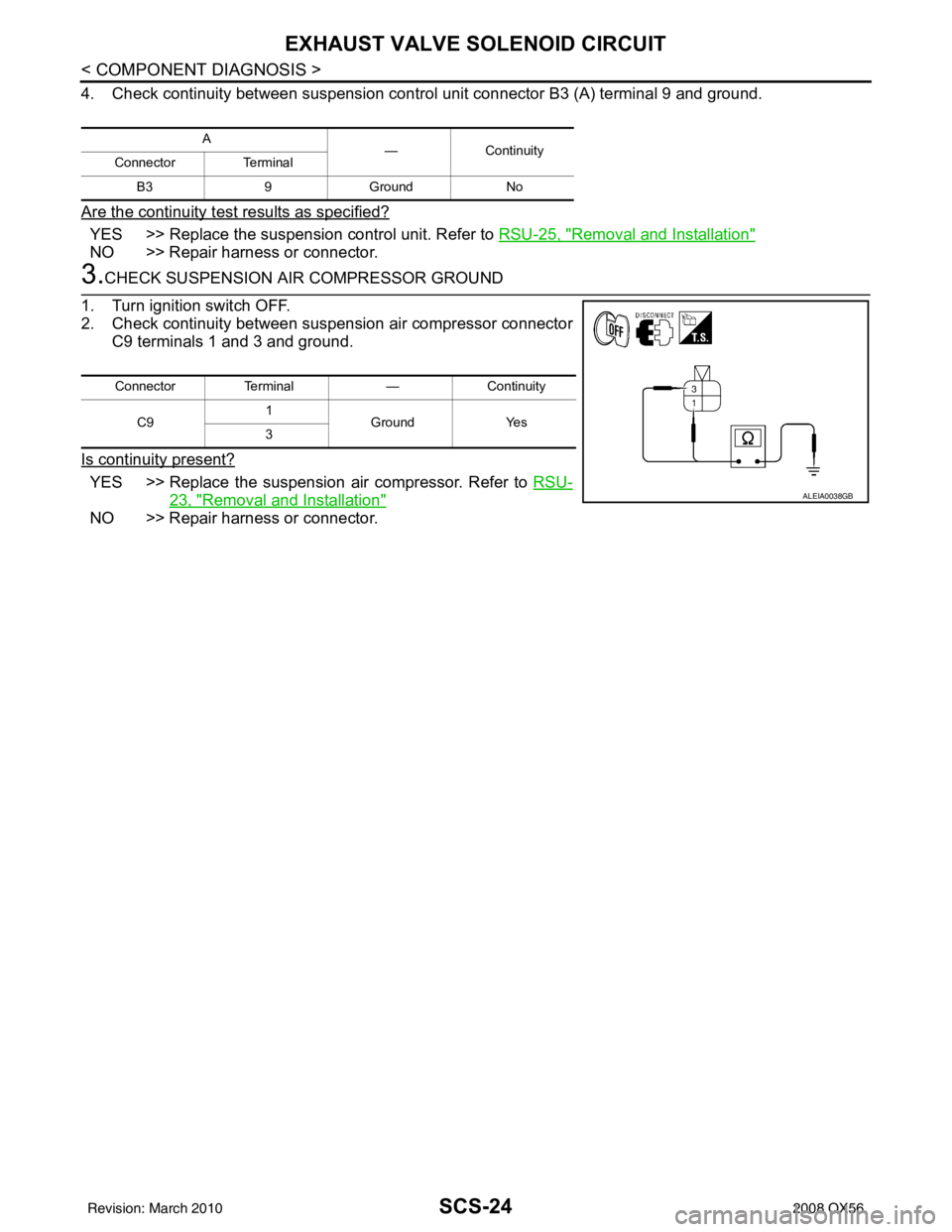
3.CHECK SUSPENSION AIR COMPRESSOR GROUND
1. Turn ignition switch OFF.
2. Check continuity between suspension air compressor connector C9 terminals 1 and 3 and ground.
Is continuity present?
YES >> Replace the suspension air compressor. Refer to RSU-
23, "Removal and Installation"
NO >> Repair harness or connector.
A
—Continuity
Connector Terminal
B3 9Ground No
ConnectorTerminal —Continuity
C9 1
Ground Yes
3
ALEIA0038GB
Revision: March 2010 2008 QX56
Page 3108 of 4083
CK SUSP WARNING INDICATOR CONTROL CIRCUITSCS-25
< COMPONENT DIAGNOSIS >
C
DF
G H
I
J
K L
M A
B
SCS
N
O P
CK SUSP WARNING INDICATOR CONTROL CIRCUIT
DescriptionINFOID:0000000001731996
The CK SUSP warning lamp is controlled by a ground signal provided to the combination meter by the sus-
pension control unit.
Component Function CheckINFOID:0000000001731997
1.CHECK WARNING LAMP OPERATION
CONSULT-III
1. Turn ignition ON.
2. Select "WARNING LAMP" of AI R LEVELIZER active test items.
3. While operating test item, check that the warning lamp activates.
Does the warning lamp operate properly?
YES >> Warning lamp is operating normally.
NO >> Refer to SCS-25, "
Diagnosis Procedure"
Diagnosis ProcedureINFOID:0000000001731998
1.PERFORM SUSPENSION CONTROL SYSTEM SELF-DIAGNOSIS
CONSULT-III
1. Turn ignition ON.
2. Perform SELF DIAGNOSIS function of AIR LEVELIZER system.
Are any DTC's present?
YES >> Refer to SCS-33, "DTC Index"
NO >> • If warning lamp is always ON, GO TO 2.
• If warning lamp is always OFF, GO TO 3
2.CHECK SUSPENSION CONTROL UNIT WARNING LAMP CONTROL
1. Turn ignition OFF.
2. Disconnect the suspension control unit connector B3.
3. Turn ignition ON.
Does the CK SUSP warning lamp turn ON?
YES >> GO TO 3.
NO >> Replace the suspension control unit. Refer to RSU-25, "
Removal and Installation"
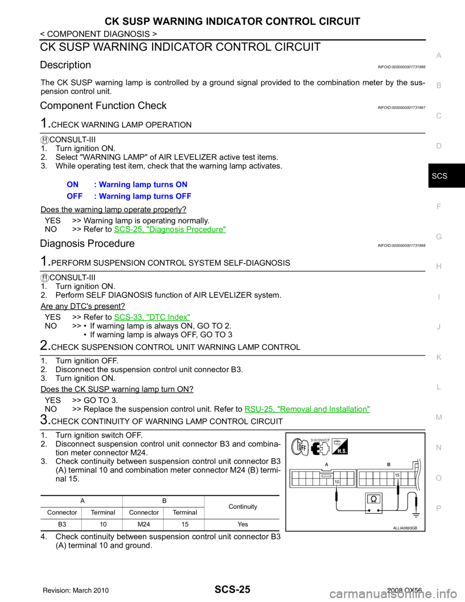
3.CHECK CONTINUITY OF WARNING LAMP CONTROL CIRCUIT
1. Turn ignition switch OFF.
2. Disconnect suspension control unit connector B3 and combina- tion meter connector M24.
3. Check continuity between suspension control unit connector B3 (A) terminal 10 and combination meter connector M24 (B) termi-
nal 15.
4. Check continuity between suspension control unit connector B3 (A) terminal 10 and ground.ON : Warning lamp turns ON
OFF : Warning lamp turns OFF
AB
Continuity
Connector Terminal Connector Terminal
B3 10 M24 15 Yes
ALLIA0693GB
Revision: March 2010 2008 QX56