2008 INFINITI QX56 fl sensor
[x] Cancel search: fl sensorPage 3716 of 4083
SYSTEM SYMPTOMTM-169
< SYMPTOM DIAGNOSIS >
CEF
G H
I
J
K L
M A
B
TM
N
O P
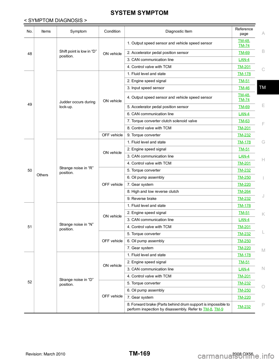
48
Others Shift point is low in “D”
position.
ON vehicle1. Output speed sensor and vehicle speed sensor
TM-48
,
TM-74
2. Accelerator pedal position sensor TM-69
3. CAN communication line LAN-4
4. Control valve with TCMTM-201
49Judder occurs during
lock-up. ON vehicle1. Fluid level and state
TM-178
2. Engine speed signal TM-51
3. Input speed sensorTM-46
4. Output speed sensor and vehicle speed sensorTM-48,
TM-74
5. Accelerator pedal position sensor TM-69
6. CAN communication line LAN-4
7. Torque converter clutch solenoid valveTM-63
8. Control valve with TCMTM-201
OFF vehicle 9. Torque converter TM-232
50Strange noise in “R”
position. ON vehicle
1. Fluid level and state
TM-178
2. Engine speed signal TM-51
3. CAN communication line LAN-4
4. Control valve with TCMTM-201
OFF vehicle5. Torque converter
TM-232
6. Oil pump assemblyTM-250
7. Gear systemTM-220
8. High and low reverse clutchTM-264
9. Reverse brakeTM-232
51Strange noise in “N”
position. ON vehicle
1. Fluid level and state
TM-178
2. Engine speed signal TM-51
3. CAN communication line LAN-4
4. Control valve with TCMTM-201
OFF vehicle5. Torque converter
TM-2326. Oil pump assemblyTM-250
7. Gear systemTM-220
52Strange noise in “D”
position. ON vehicle
1. Fluid level and state
TM-178
2. Engine speed signal TM-51
3. CAN communication line LAN-4
4. Control valve with TCMTM-201
OFF vehicle5. Torque converter
TM-232
6. Oil pump assemblyTM-250
7. Gear systemTM-220
8. Forward brake (Parts behind drum support is impossible to
perform inspection by disassembly. Refer to TM-8
, TM-9TM-232
No. Items Symptom Condition Diagnostic ItemReference
page
Revision: March 2010 2008 QX56
Page 3718 of 4083
SYSTEM SYMPTOMTM-171
< SYMPTOM DIAGNOSIS >
CEF
G H
I
J
K L
M A
B
TM
N
O P
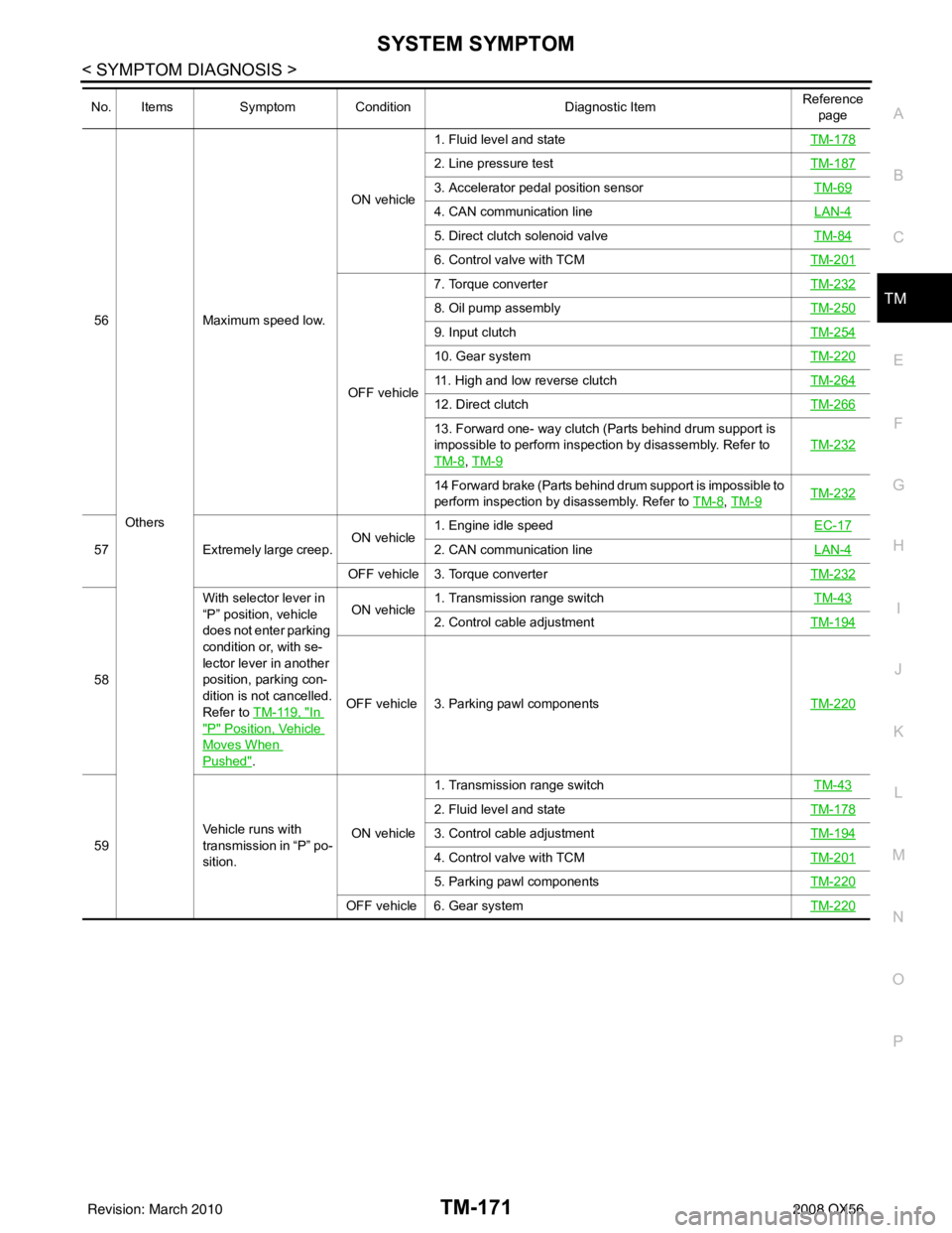
56
Others Maximum speed low.
ON vehicle
1. Fluid level and state
TM-178
2. Line pressure testTM-187
3. Accelerator pedal position sensor TM-69
4. CAN communication line LAN-4
5. Direct clutch solenoid valveTM-84
6. Control valve with TCMTM-201
OFF vehicle7. Torque converter
TM-232
8. Oil pump assemblyTM-250
9. Input clutchTM-254
10. Gear systemTM-220
11. High and low reverse clutchTM-264
12. Direct clutchTM-266
13. Forward one- way clutch (Parts behind drum support is
impossible to perform inspection by disassembly. Refer to
TM-8
, TM-9
TM-232
14 Forward brake (Parts behind drum support is impossible to
perform inspection by disassembly. Refer to TM-8
, TM-9TM-232
57 Extremely large creep. ON vehicle1. Engine idle speed
EC-172. CAN communication lineLAN-4
OFF vehicle 3. Torque converter TM-232
58With selector lever in
“P” position, vehicle
does not enter parking
condition or, with se-
lector lever in another
position, parking con-
dition is not cancelled.
Refer to
TM-119, "
In
"P" Position, Vehicle
Moves When
Pushed". ON vehicle
1. Transmission range switch
TM-43
2. Control cable adjustmentTM-194
OFF vehicle 3. Parking pawl components TM-220
59Vehicle runs with
transmission in “P” po-
sition. ON vehicle1. Transmission range switch
TM-43
2. Fluid level and stateTM-178
3. Control cable adjustmentTM-194
4. Control valve with TCMTM-201
5. Parking pawl componentsTM-220
OFF vehicle 6. Gear system TM-220
No. ItemsSymptom Condition Diagnostic ItemReference
page
Revision: March 2010 2008 QX56
Page 3719 of 4083
TM-172
< SYMPTOM DIAGNOSIS >
SYSTEM SYMPTOM
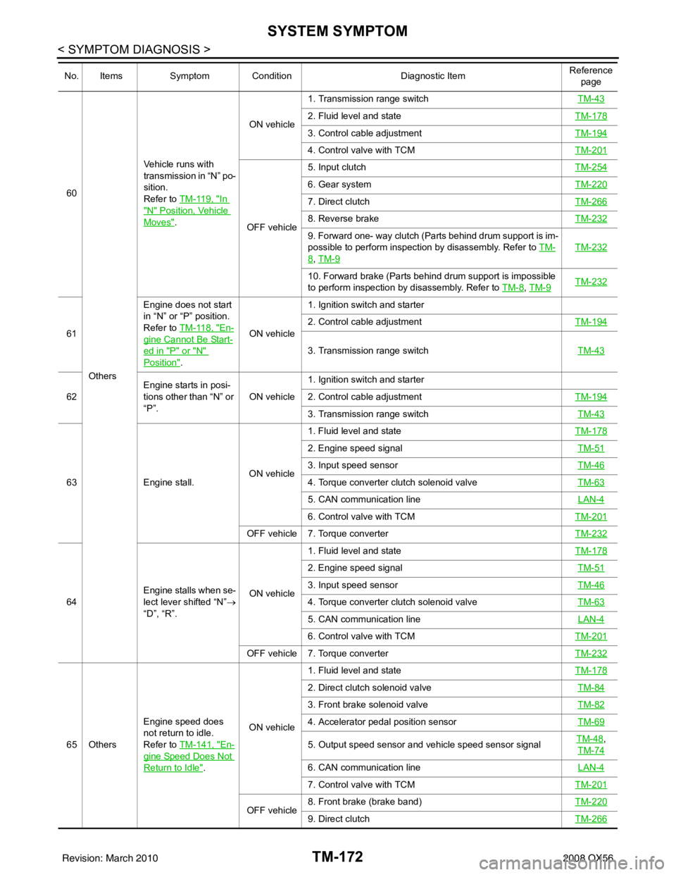
60Others Vehicle runs with
transmission in “N” po-
sition.
Refer to TM-119, "In
"N" Position, Vehicle
Moves".
ON vehicle
1. Transmission range switch
TM-43
2. Fluid level and stateTM-178
3. Control cable adjustmentTM-194
4. Control valve with TCMTM-201
OFF vehicle5. Input clutch
TM-254
6. Gear systemTM-220
7. Direct clutchTM-266
8. Reverse brakeTM-232
9. Forward one- way clutch (Parts behind drum support is im-
possible to perform inspection by disassembly. Refer to TM-
8, TM-9
TM-232
10. Forward brake (Parts behind drum support is impossible
to perform inspection by disassembly. Refer to TM-8
, TM-9TM-232
61 Engine does not start
in “N” or “P” position.
Refer to TM-118, "En-
gine Cannot Be Start-
ed in "P" or "N"
Position".ON vehicle1. Ignition switch and starter
2. Control cable adjustment
TM-194
3. Transmission range switch TM-43
62Engine starts in posi-
tions other than “N” or
“P”.
ON vehicle1. Ignition switch and starter
2. Control cable adjustment
TM-194
3. Transmission range switch TM-43
63Engine stall. ON vehicle1. Fluid level and state
TM-178
2. Engine speed signal TM-51
3. Input speed sensorTM-46
4. Torque converter clutch solenoid valveTM-63
5. CAN communication line LAN-4
6. Control valve with TCMTM-201
OFF vehicle 7. Torque converter TM-232
64Engine stalls when se-
lect lever shifted “N”
→
“D”, “R”. ON vehicle1. Fluid level and state
TM-178
2. Engine speed signal TM-51
3. Input speed sensorTM-46
4. Torque converter clutch solenoid valveTM-63
5. CAN communication line LAN-4
6. Control valve with TCMTM-201
OFF vehicle 7. Torque converter TM-232
65 OthersEngine speed does
not return to idle.
Refer to TM-141, "En-
gine Speed Does Not
Return to Idle".ON vehicle 1. Fluid level and state
TM-178
2. Direct clutch solenoid valve TM-84
3. Front brake solenoid valveTM-82
4. Accelerator pedal position sensorTM-69
5. Output speed sensor and vehicle speed sensor signalTM-48,
TM-74
6. CAN communication line LAN-4
7. Control valve with TCMTM-201
OFF vehicle8. Front brake (brake band)
TM-2209. Direct clutchTM-266
No. ItemsSymptom Condition Diagnostic ItemReference
page
Revision: March 2010 2008 QX56
Page 3720 of 4083
PRECAUTIONSTM-173
< PRECAUTION >
CEF
G H
I
J
K L
M A
B
TM
N
O P
PRECAUTION
PRECAUTIONS
Precaution for Supplemental Restraint System (SRS) "AIR BAG" and "SEAT BELT
PRE-TENSIONER"
INFOID:0000000006054118
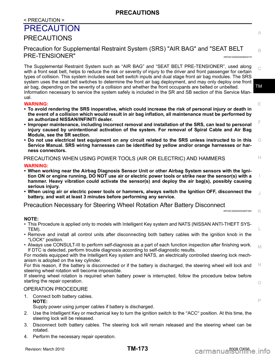
The Supplemental Restraint System such as “AIR BAG” and “SEAT BELT PRE-TENSIONER”, used along
with a front seat belt, helps to reduce the risk or severi ty of injury to the driver and front passenger for certain
types of collision. This system includes seat belt switch inputs and dual stage front air bag modules. The SRS
system uses the seat belt switches to determine the front air bag deployment, and may only deploy one front
air bag, depending on the severity of a collision and w hether the front occupants are belted or unbelted.
Information necessary to service the system safely is included in the SR and SB section of this Service Man-
ual.
WARNING:
• To avoid rendering the SRS inoper ative, which could increase the risk of personal injury or death in
the event of a collision which would result in air bag inflation, all maintenance must be performed by
an authorized NISSAN/INFINITI dealer.
• Improper maintenance, including in correct removal and installation of the SRS, can lead to personal
injury caused by unintentional act ivation of the system. For removal of Spiral Cable and Air Bag
Module, see the SR section.
• Do not use electrical test equipm ent on any circuit related to the SRS unless instructed to in this
Service Manual. SRS wiring harnesses can be identi fied by yellow and/or orange harnesses or har-
ness connectors.
PRECAUTIONS WHEN USING POWER TOOLS (AIR OR ELECTRIC) AND HAMMERS
WARNING:
• When working near the Airbag Diagnosis Sensor Un it or other Airbag System sensors with the Igni-
tion ON or engine running, DO NOT use air or el ectric power tools or strike near the sensor(s) with a
hammer. Heavy vibration could activate the sensor( s) and deploy the air bag(s), possibly causing
serious injury.
• When using air or electric power tools or hammers, always switch the Ignition OFF, disconnect the battery, and wait at least 3 minutes before performing any service.
Precaution Necessary for Steering Wheel Rotation After Battery Disconnect
INFOID:0000000004857582
NOTE:
• This Procedure is applied only to models with Intelligent Key system and NATS (NISSAN ANTI-THEFT SYS-
TEM).
• Remove and install all control units after disconnecti ng both battery cables with the ignition knob in the
″ LOCK ″ position.
• Always use CONSULT-III to perform self-diagnosis as a part of each function inspection after finishing work.
If DTC is detected, perform trouble diagnosis according to self-diagnostic results.
For models equipped with the Intelligent Key system and NATS , an electrically controlled steering lock mech-
anism is adopted on the key cylinder.
For this reason, if the battery is disconnected or if the battery is discharged, the steering wheel will lock and
steering wheel rotation will become impossible.
If steering wheel rotation is required when battery power is interrupted, follow the procedure below before
starting the repair operation.
OPERATION PROCEDURE
1. Connect both battery cables. NOTE:
Supply power using jumper cables if battery is discharged.
2. Use the Intelligent Key or mechanical key to turn the ignition switch to the ″ACC ″ position. At this time, the
steering lock will be released.
3. Disconnect both battery cables. The steering lock will remain released and the steering wheel can be
rotated.
4. Perform the necessary repair operation.
Revision: March 2010 2008 QX56
Page 3721 of 4083
TM-174
< PRECAUTION >
PRECAUTIONS
5. When the repair work is completed, return the ignition switch to the ″LOCK ″ position before connecting
the battery cables. (At this time, the steering lock mechanism will engage.)
6. Perform a self-diagnosis check of a ll control units using CONSULT-III.
Precaution for On Board Diagnosis (OBD) System of A/T and EngineINFOID:0000000001531485
The ECM has an on board diagnostic system. It will light up the malfunction indicator lamp (MIL) to warn the
driver of a malfunction causing emission deterioration.
CAUTION:
• Be sure to turn the ignition switch “OFF” and disconnect the negative battery cable before any repair
or inspection work. The open/short circuit of related switches, sensors, solenoid valves, etc. Will
cause the MIL to light up.
• Be sure to connect and lock the connectors secure ly after work. A loose (unlocked) connector will
cause the MIL to light up due to an open circuit. (Be sure the connector is free from water, grease,
dirt, bent terminals, etc.)
• Be sure to route and secure th e harnesses properly after work. Interference of the harness with a
bracket, etc. May cause the MIL to light up due to a short circuit.
• Be sure to connect rubber tubes properly afte r work. A misconnected or disconnected rubber tube
may cause the MIL to light up due to a malfunction of the EGR system or fuel injection system, etc.
• Be sure to erase the unnecessary malfunction informa tion (repairs completed) from the TCM and
ECM before returning the vehicle to the customer.
PrecautionINFOID:0000000001531486
NOTE:
If any malfunctions occur in the RE5R05A model tr ansmission, replace the entire transmission assem-
bly.
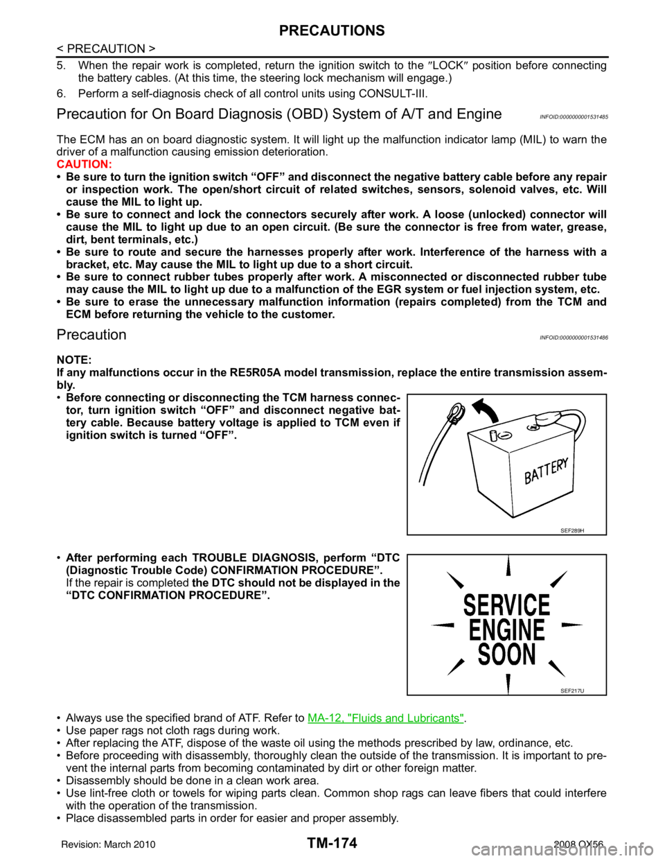
• Before connecting or disconn ecting the TCM harness connec-
tor, turn ignition switch “O FF” and disconnect negative bat-
tery cable. Because battery voltage is applied to TCM even if
ignition switch is turned “OFF”.
• After performing each TROUBLE DIAGNOSIS, perform “DTC
(Diagnostic Trouble Code) CONFIRMATION PROCEDURE”.
If the repair is completed the DTC should not be displayed in the
“DTC CONFIRMATION PROCEDURE”.
• Always use the specified brand of ATF. Refer to MA-12, "
Fluids and Lubricants".
• Use paper rags not cloth rags during work.
• After replacing the ATF, dispose of the waste oil using the methods prescribed by law, ordinance, etc.
• Before proceeding with disassembly, thoroughly clean the outside of the transmission. It is important to pre- vent the internal parts from becoming cont aminated by dirt or other foreign matter.
• Disassembly should be done in a clean work area.
• Use lint-free cloth or towels for wiping parts clean. Common shop rags can leave fibers that could interfere
with the operation of the transmission.
• Place disassembled parts in order for easier and proper assembly.
SEF289H
SEF217U
Revision: March 2010 2008 QX56
Page 3735 of 4083
TM-188
< ON-VEHICLE MAINTENANCE >
LINE PRESSURE TEST
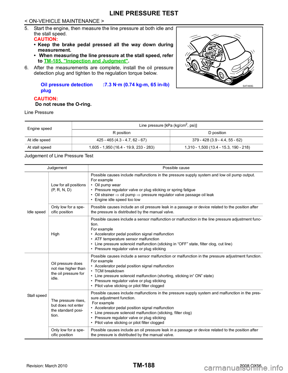
5. Start the engine, then measure the line pressure at both idle andthe stall speed.
CAUTION:
• Keep the brake pedal pressed all the way down duringmeasurement.
• When measuring the line pressure at the stall speed, refer
to TM-185, "
Inspection and Judgment".
6. After the measurements are complete, install the oil pressure detection plug and tighten to the regulation torque below.
CAUTION:
Do not reuse the O-ring.
Line Pressure
Judgement of Line Pressure Test
Oil pressure detection
plug :7.3 N·m (0.74 kg-m, 65 in-lb)SAT493G
Engine speed
Line pressure [kPa (kg/cm
2, psi)]
R position D position
At idle speed 425 - 465 (4.3 - 4.7, 62 - 67) 379 - 428 (3.9 - 4.4, 55 - 62)
At stall speed 1,605 - 1,950 (16.4 - 19.9, 233 - 283) 1,310 - 1,500 (13.4 - 15.3, 190 - 218)
Judgement Possible cause
Idle speed Low for all positions
(P, R, N, D)
Possible causes include malfunctions in the pressure supply system and low oil pump output.
For example
•Oil pump wear
• Pressure regulator valve or plug sticking or spring fatigue
• Oil strainer ⇒ oil pump
⇒ pressure regulator valve passage oil leak
• Engine idle speed too low
Only low for a spe-
cific position Possible causes include an oil pressure leak in a passage or device related to the position after
the pressure is distributed by the manual valve.
High Possible causes include a sensor malfunction or malfunction in the line pressure adjustment func-
tion.
For example
• Accelerator pedal position signal malfunction
• ATF temperature sensor malfunction
• Line pressure solenoid malfunction (sticking in “OFF” state, filter clog, cut line)
• Pressure regulator valve or plug sticking
Sta ll sp ee d Oil pressure does
not rise higher than
the oil pressure for
idle.
Possible causes include a sensor malfunction or malfunction in the pressure adjustment function.
For example
• Accelerator pedal position signal malfunction
• TCM breakdown
• Line pressure solenoid malfunction (shorting, sticking in“ ON” state)
• Pressure regulator valve or plug sticking
• Pilot valve sticking or pilot filter clogged
The pressure rises,
but does not enter
the standard posi-
tion. Possible causes include malfunctions in the pressure supply system and malfunction in the pres-
sure adjustment function.
For example
• Accelerator pedal position signal malfunction
• Line pressure solenoid malfunction (sticking, filter clog)
• Pressure regulator valve or plug sticking
• Pilot valve sticking or pilot filter clogged
Only low for a spe-
cific position Possible causes include an oil pressure leak in a passage or device related to the position after
the pressure is distributed by the manual valve.
Revision: March 2010
2008 QX56
Page 3748 of 4083
CONTROL VALVE WITH TCMTM-201
< ON-VEHICLE REPAIR >
CEF
G H
I
J
K L
M A
B
TM
N
O P
CONTROL VALVE WITH TCM
Control Valve with TCM and A/T Fluid Temperature Sensor 2INFOID:0000000006211127
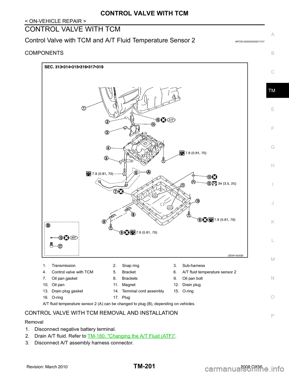
COMPONENTS
CONTROL VALVE WITH TCM REMOVAL AND INSTALLATION
Removal
1. Disconnect negative battery terminal.
2. Drain A/T fluid. Refer to TM-180, "
Changing the A/T Fluid (ATF)".
3. Disconnect A/T assembly harness connector.
1. Transmission 2. Snap ring3. Sub-harness
4. Control valve with TCM 5. Bracket6. A/T fluid temperature sensor 2
7. Oil pan gasket 8. Brackets9. Oil pan bolt
10. Oil pan 11. Magnet12. Drain plug
13. Drain plug gasket 14. Terminal cord assembly 15. O-ring
16. O-ring 17. Plug
A/T fluid temperature sensor 2 (A) can be changed to plug (B), depending on vehicles.
JSDIA1425GB
Revision: March 2010 2008 QX56
Page 3749 of 4083
TM-202
< ON-VEHICLE REPAIR >
CONTROL VALVE WITH TCM
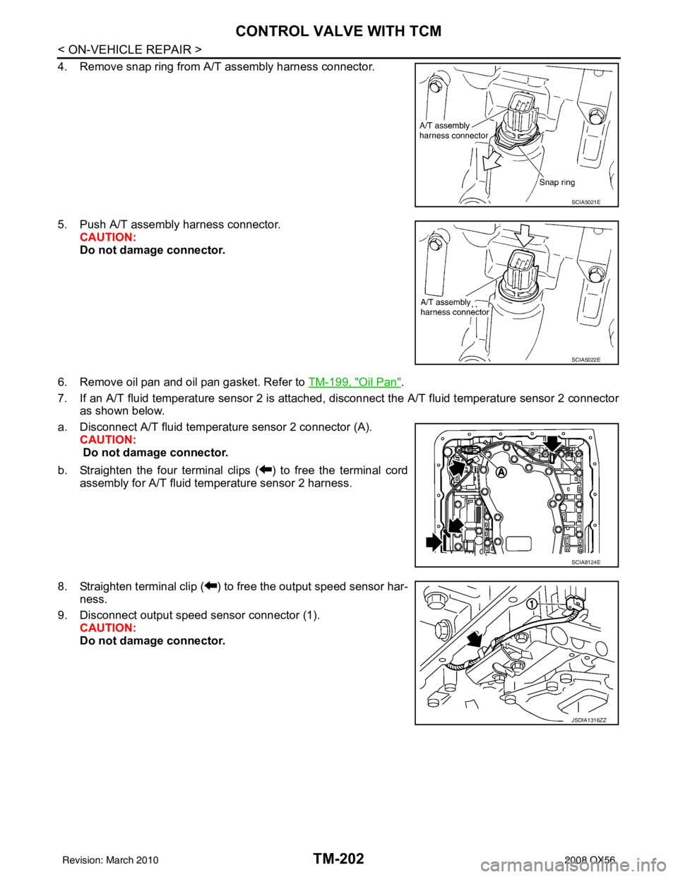
4. Remove snap ring from A/T assembly harness connector.
5. Push A/T assembly harness connector.CAUTION:
Do not damage connector.
6. Remove oil pan and oil pan gasket. Refer to TM-199, "
Oil Pan".
7. If an A/T fluid temperature sensor 2 is attached, disconnect the A/T fluid temperature sensor 2 connector
as shown below.
a. Disconnect A/T fluid temperat ure sensor 2 connector (A).
CAUTION:
Do not damage connector.
b. Straighten the four terminal clips ( ) to free the terminal cord assembly for A/T fluid temperature sensor 2 harness.
8. Straighten terminal clip ( ) to free the output speed sensor har- ness.
9. Disconnect output speed sensor connector (1). CAUTION:
Do not damage connector.
SCIA5021E
SCIA5022E
SCIA8124E
JSDIA1316ZZ
Revision: March 2010 2008 QX56