2008 INFINITI QX56 engine
[x] Cancel search: enginePage 3761 of 4083
TM-214
< REMOVAL AND INSTALLATION >
TRANSMISSION ASSEMBLY
REMOVAL AND INSTALLATION
TRANSMISSION ASSEMBLY
Removal and Installation (2WD)INFOID:0000000004917498
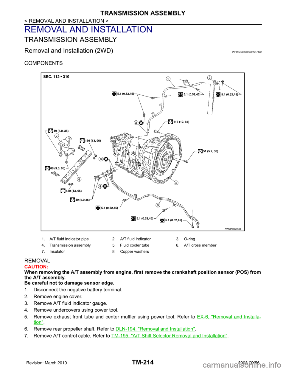
COMPONENTS
REMOVAL
CAUTION:
When removing the A/T assembly from engine, first remove the crankshaft position sensor (POS) from
the A/T assembly.
Be careful not to damage sensor edge.
1. Disconnect the negative battery terminal.
2. Remove engine cover.
3. Remove A/T fluid indicator gauge.
4. Remove undercovers using power tool.
5. Remove exhaust front tube and center muffler using power tool. Refer to EX-6, "
Removal and Installa-
tion".
6. Remove rear propeller shaft. Refer to DLN-194, "
Removal and Installation".
7. Remove A/T control cable. Refer to TM-195, "
A/T Shift Selector Removal and Installation".
1. A/T fluid indicator pipe 2. A/T fluid indicator 3. O-ring
4. Transmission assembly 5. Fluid cooler tube6. A/T cross member
7. Insulator 8. Copper washers
AWDIA0679GB
Revision: March 2010 2008 QX56
Page 3762 of 4083
TRANSMISSION ASSEMBLYTM-215
< REMOVAL AND INSTALLATION >
CEF
G H
I
J
K L
M A
B
TM
N
O P
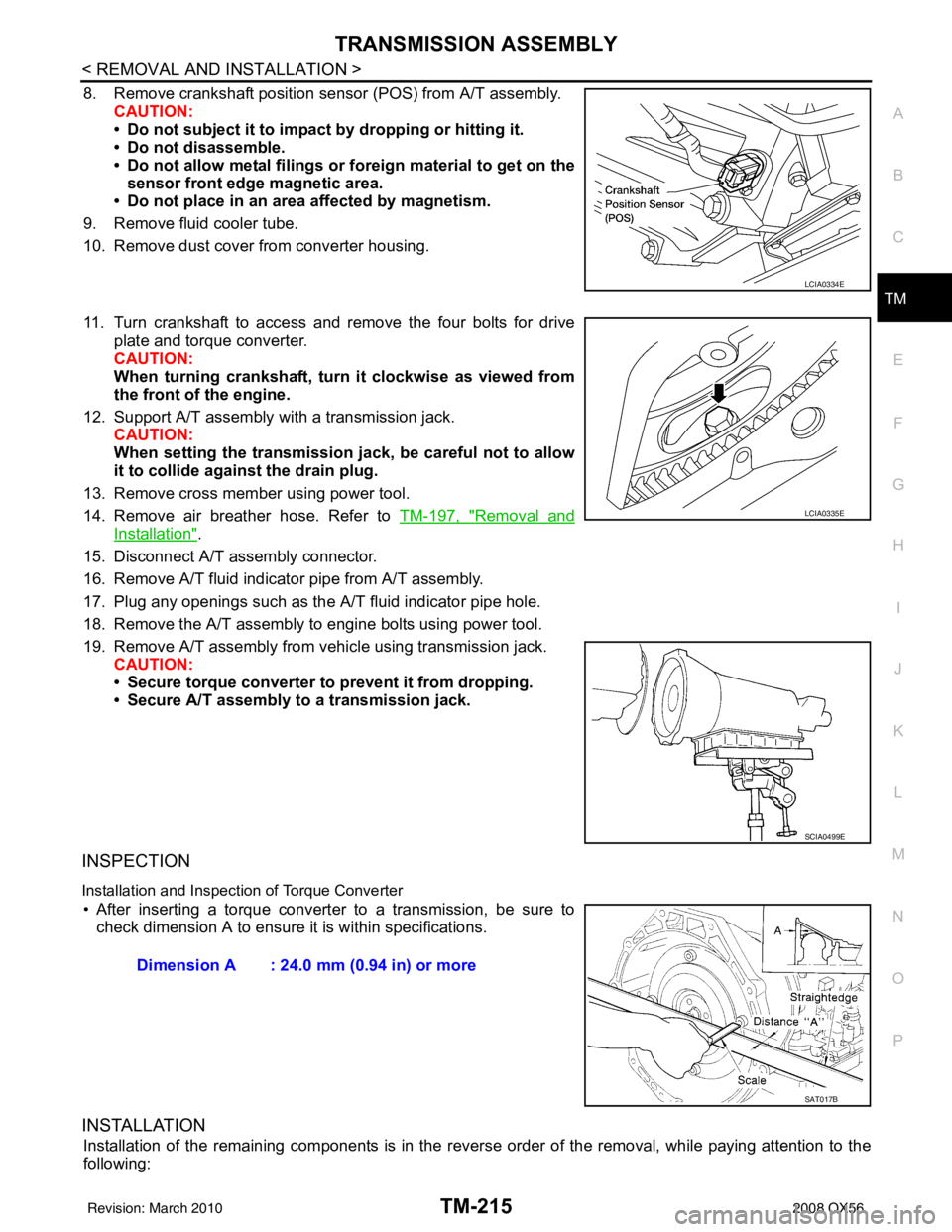
8. Remove crankshaft position sens or (POS) from A/T assembly.
CAUTION:
• Do not subject it to impact by dropping or hitting it.
• Do not disassemble.
• Do not allow metal filings or foreign material to get on the
sensor front edge magnetic area.
• Do not place in an area affected by magnetism.
9. Remove fluid cooler tube.
10. Remove dust cover from converter housing.
11. Turn crankshaft to access and remove the four bolts for drive plate and torque converter.
CAUTION:
When turning crankshaft, turn it clockwise as viewed from
the front of the engine.
12. Support A/T assembly with a transmission jack. CAUTION:
When setting the transmission jack, be careful not to allow
it to collide agai nst the drain plug.
13. Remove cross member using power tool.
14. Remove air breather hose. Refer to TM-197, "
Removal and
Installation".
15. Disconnect A/T assembly connector.
16. Remove A/T fluid indicator pipe from A/T assembly.
17. Plug any openings such as the A/T fluid indicator pipe hole.
18. Remove the A/T assembly to engine bolts using power tool.
19. Remove A/T assembly from vehicle using transmission jack. CAUTION:
• Secure torque converter to prevent it from dropping.
• Secure A/T assembly to a transmission jack.
INSPECTION
Installation and Inspection of Torque Converter
• After inserting a torque converter to a transmission, be sure to check dimension A to ensure it is within specifications.
INSTALLATION
Installation of the remaining components is in the revers e order of the removal, while paying attention to the
following:
LCIA0334E
LCIA0335E
SCIA0499E
Dimension A : 24.0 mm (0.94 in) or more
SAT017B
Revision: March 2010 2008 QX56
Page 3763 of 4083
TM-216
< REMOVAL AND INSTALLATION >
TRANSMISSION ASSEMBLY
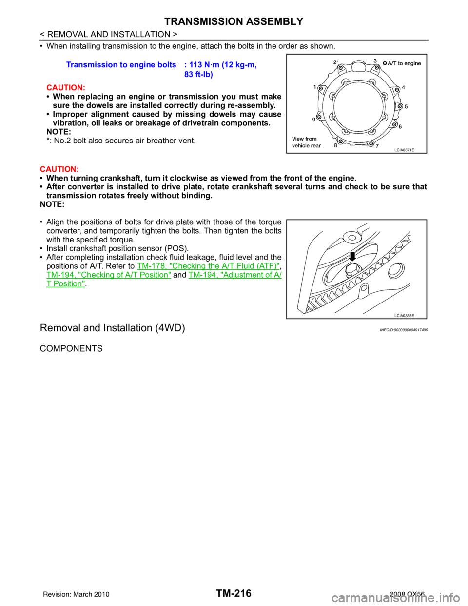
• When installing transmission to the engine, attach the bolts in the order as shown.CAUTION:
• When replacing an engine or transmission you must make
sure the dowels are installe d correctly during re-assembly.
• Improper alignment caused by missing dowels may cause
vibration, oil leaks or breakage of drivetrain components.
NOTE:
*: No.2 bolt also secures air breather vent.
CAUTION:
• When turning crankshaft, turn it clockwi se as viewed from the front of the engine.
• After converter is installed to drive plate, rota te crankshaft several turns and check to be sure that
transmission rotates fr eely without binding.
NOTE:
• Align the positions of bolts for drive plate with those of the torque converter, and temporarily tighten the bolts. Then tighten the bolts
with the specified torque.
• Install crankshaft pos ition sensor (POS).
• After completing installation check fluid leakage, fluid level and the positions of A/T. Refer to TM-178, "
Checking the A/T Fluid (ATF)",
TM-194, "
Checking of A/T Position" and TM-194, "Adjustment of A/
T Position".
Removal and Installation (4WD)INFOID:0000000004917499
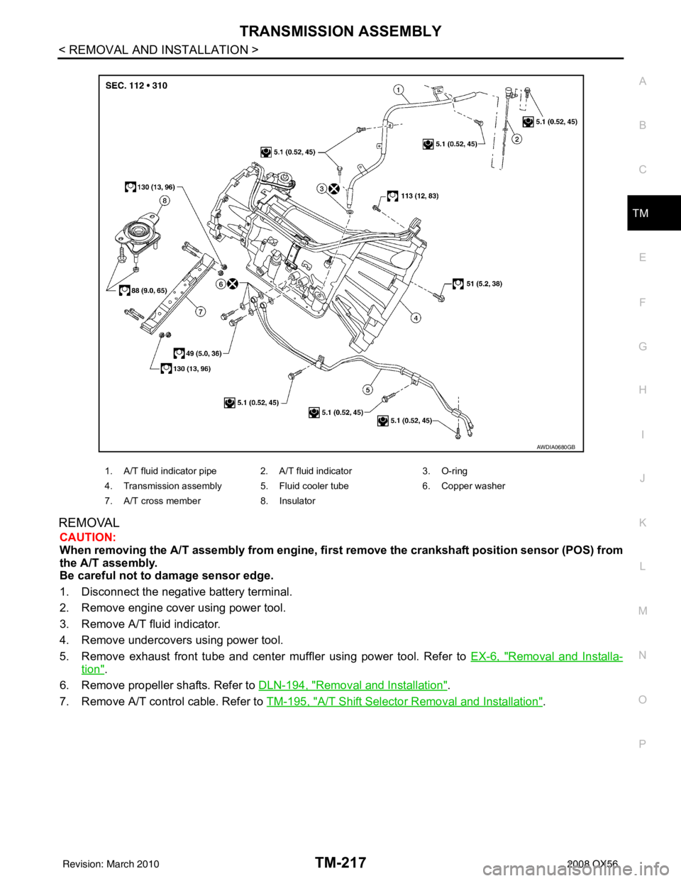
COMPONENTS
Transmission to engine bolts : 113 N·m (12 kg-m,
83 ft-lb)
LCIA0371E
LCIA0335E
Revision: March 2010 2008 QX56
Page 3764 of 4083
TRANSMISSION ASSEMBLYTM-217
< REMOVAL AND INSTALLATION >
CEF
G H
I
J
K L
M A
B
TM
N
O P
REMOVAL
CAUTION:
When removing the A/T assembly from engine, firs t remove the crankshaft position sensor (POS) from
the A/T assembly.
Be careful not to damage sensor edge.
1. Disconnect the negative battery terminal.
2. Remove engine cover using power tool.
3. Remove A/T fluid indicator.
4. Remove undercovers using power tool.
5. Remove exhaust front tube and center muffler using power tool. Refer to EX-6, "
Removal and Installa-
tion".
6. Remove propeller shafts. Refer to DLN-194, "
Removal and Installation".
7. Remove A/T control cable. Refer to TM-195, "
A/T Shift Selector Removal and Installation".
1. A/T fluid indicator pipe 2. A/T fluid indicator 3. O-ring
4. Transmission assembly 5. Fluid cooler tube 6. Copper washer
7. A/T cross member 8. Insulator
AWDIA0680GB
Revision: March 2010 2008 QX56
Page 3765 of 4083
TM-218
< REMOVAL AND INSTALLATION >
TRANSMISSION ASSEMBLY
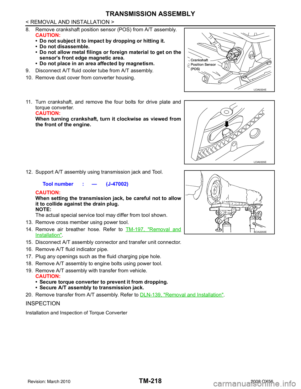
8. Remove crankshaft position sensor (POS) from A/T assembly.CAUTION:
• Do not subject it to impact by dropping or hitting it.
• Do not disassemble.
• Do not allow metal filings or fo reign material to get on the
sensor's front edge magnetic area.
• Do not place in an area affected by magnetism.
9. Disconnect A/T fluid cooler tube from A/T assembly.
10. Remove dust cover from converter housing.
11. Turn crankshaft, and remove the four bolts for drive plate and torque converter.
CAUTION:
When turning crankshaft, turn it clockwise as viewed from
the front of the engine.
12. Support A/T assembly using transmission jack and Tool. CAUTION:
When setting the transmission j ack, be careful not to allow
it to collide agai nst the drain plug.
NOTE:
The actual special service tool may differ from tool shown.
13. Remove cross member using power tool.
14. Remove air breather hose. Refer to TM-197, "
Removal and
Installation".
15. Disconnect A/T assembly connector and transfer unit connector.
16. Remove A/T fluid indicator pipe.
17. Plug any openings such as the fluid charging pipe hole.
18. Remove A/T assembly to engine bolts using power tool.
19. Remove A/T assembly with transfer from vehicle. CAUTION:
• Secure torque converter to prevent it from dropping.
• Secure A/T assembly to transmission jack.
20. Remove transfer from A/T assembly. Refer to DLN-139, "
Removal and Installation".
INSPECTION
Installation and Inspection of Torque Converter
LCIA0334E
LCIA0335E
Tool number : — (J-47002)
SCIA2203E
Revision: March 2010 2008 QX56
Page 3766 of 4083
TRANSMISSION ASSEMBLYTM-219
< REMOVAL AND INSTALLATION >
CEF
G H
I
J
K L
M A
B
TM
N
O P
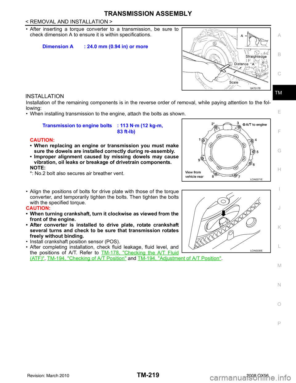
• After inserting a torque converter to a transmission, be sure to check dimension A to ensure it is within specifications.
INSTALLATION
Installation of the remaining components is in the revers e order of removal, while paying attention to the fol-
lowing:
• When installing transmission to the engine, attach the bolts as shown.
CAUTION:
• When replacing an engine or transmission you must make sure the dowels are installed correctly during re-assembly.
• Improper alignment caused by missing dowels may cause
vibration, oil leaks or breakage of drivetrain components.
NOTE:
*: No.2 bolt also secures air breather vent.
• Align the positions of bolts for dr ive plate with those of the torque
converter, and temporarily tighten the bolts. Then tighten the bolts
with the specified torque.
CAUTION:
• When turning crankshaft, turn it clockwise as viewed from the
front of the engine.
• After converter is installed to drive plate, rotate crankshaft several turns and check to be sure that transmission rotates
freely without binding.
• Install crankshaft position sensor (POS).
• After completing installation, check fluid leakage, fluid level, and the positions of A/T. Refer to TM-178, "
Checking the A/T Fluid
(ATF)", TM-194, "Checking of A/T Position" and TM-194, "Adjustment of A/T Position".
Dimension A : 24.0 mm (0.94 in) or more
SAT017B
Transmission to engine bolts : 113 N·m (12 kg-m,
83 ft-lb)
LCIA0371E
LCIA0335E
Revision: March 2010 2008 QX56
Page 3839 of 4083

TM-292
< SERVICE DATA AND SPECIFICATIONS (SDS)
SERVICE DATA AND SPECIFICATIONS (SDS)
Stall Speed
INFOID:0000000004917908
Line PressureINFOID:0000000004917909
A/T Fluid Temperature SensorINFOID:0000000004917910
Input Speed SensorINFOID:0000000004917911
Output Speed SensorINFOID:0000000004917912
Reverse BrakeINFOID:0000000004917913
Total End PlayINFOID:0000000004917914
BEARING RACE FOR ADJUSTING TOTAL END PLAY
Stall speed 2,700 – 3,000 rpm
Engine speedLine pressure kPa (kg/cm2, psi)
“R” position “D” position
At idle speed 425 – 465 (4.3 – 4.7, 62 – 67) 379 – 428 (3.9 – 4.4, 55 – 62)
At stall speed 1,605 – 1,950 (16.4 – 19.9, 233 – 283) 1,310 – 1,500 (13.4 – 15.3, 190 – 218)
NameCondition CONSULT-I II “DATA MONITOR” (Approx.) (V) Resistance (Approx.) (k Ω)
ATF TEMP SE 1 0
°C (32 °F) 3.3 15
20 °C (68 °F) 2.7 6.5
80 °C (176 °F) 0.9 0.9
Name ConditionData (Approx.)
Input speed sensor 1 When running at 50 km/h (31 MPH) in 4th speed witch the closed throttle position
signal OFF.
1.3 kHz
Input speed sensor 2 When running at 20 km/h (12 MPH) in 1st speed witch the closed throttle position
signal OFF.
Name
ConditionData (Approx.)
Output speed sensor When running at 20 km/h (12 MPH). 185 Hz
Model code number 97X2E, 97X3A
Number of drive plates 6
Number of driven plates 6
Clearance mm (in) Standard 0.7 – 1.1 (0.028 – 0.043)
Thickness of retaining plates Thickness mm (in)
4.2 (0.165)
4.4 (0.173)
4.6 (0.181)
4.8 (0.189)
5.0 (0.197)
5.2 (0.205)
Total end play mm (in) 0.25 – 0.55 (0.0098 – 0.0217)
Revision: March 2010 2008 QX56
Page 3842 of 4083
VTL-2
< PRECAUTION >
PRECAUTIONS
PRECAUTION
PRECAUTIONS
Precaution for Supplemental Restraint System (SRS) "AIR BAG" and "SEAT BELT
PRE-TENSIONER"
INFOID:0000000004884177
The Supplemental Restraint System such as “A IR BAG” and “SEAT BELT PRE-TENSIONER”, used along
with a front seat belt, helps to reduce the risk or severity of injury to the driver and front passenger for certain
types of collision. This system includes seat belt switch inputs and dual stage front air bag modules. The SRS
system uses the seat belt switches to determine the front air bag deployment, and may only deploy one front
air bag, depending on the severity of a collision and w hether the front occupants are belted or unbelted.
Information necessary to service the system safely is included in the SR and SB section of this Service Man-
ual.
WARNING:
• To avoid rendering the SRS inopera tive, which could increase the risk of personal injury or death in
the event of a collision which would result in air bag inflation, all maintenance must be performed by
an authorized NISSAN/INFINITI dealer.
• Improper maintenance, including in correct removal and installation of the SRS, can lead to personal
injury caused by unintent ional activation of the system. For re moval of Spiral Cable and Air Bag
Module, see the SR section.
• Do not use electrical test equipmen t on any circuit related to the SRS unless instructed to in this
Service Manual. SRS wiring harn esses can be identified by yellow and/or orange harnesses or har-
ness connectors.
PRECAUTIONS WHEN USING POWER TOOLS (AIR OR ELECTRIC) AND HAMMERS
WARNING:
• When working near the Airbag Diagnosis Sensor Unit or other Airbag System sensors with the Igni-
tion ON or engine running, DO NOT use air or electri c power tools or strike near the sensor(s) with a
hammer. Heavy vibration could activate the sensor( s) and deploy the air bag(s), possibly causing
serious injury.
• When using air or electric power tools or hammers , always switch the Ignition OFF, disconnect the
battery, and wait at least 3 minu tes before performing any service.
Precaution Necessary for Steering W heel Rotation After Battery Disconnect
INFOID:0000000004884178
NOTE:
• This Procedure is applied only to models with Intelligent Key system and NATS (NISSAN ANTI-THEFT SYS-
TEM).
• Remove and install all control units after disconnecting both battery cables with the ignition knob in the
″LOCK ″ position.
• Always use CONSULT-III to perform self-diagnosis as a part of each function inspection after finishing work.
If DTC is detected, perform trouble diagnosis according to self-diagnostic results.
For models equipped with the Intelligent Key system and NATS, an electrically controlled steering lock mech-
anism is adopted on the key cylinder.
For this reason, if the battery is disconnected or if the battery is discharged, the steering wheel will lock and
steering wheel rotation will become impossible.
If steering wheel rotation is required when battery pow er is interrupted, follow the procedure below before
starting the repair operation.
OPERATION PROCEDURE
1. Connect both battery cables. NOTE:
Supply power using jumper cables if battery is discharged.
2. Use the Intelligent Key or mechanical key to turn the ignition switch to the ″ACC ″ position. At this time, the
steering lock will be released.
3. Disconnect both battery cables. The steering lock will remain released and the steering wheel can be rotated.
4. Perform the necessary repair operation.
Revision: March 2010 2008 QX56