2008 INFINITI QX56 coolant temperature
[x] Cancel search: coolant temperaturePage 2606 of 4083
MA-8
< ON-VEHICLE MAINTENANCE >
PERIODIC MAINTENANCE
PERIODIC MAINTENANCE
Introduction of Periodic MaintenanceINFOID:0000000001606164
Two different maintenance schedules are provided, and should be used, depending upon the conditions in
which the vehicle is mainly operated. After 60,000 miles (96,000 km) or 48 months, continue the periodic
maintenance at the same mileage or ti me intervals, whichever comes first.
Maintenance for Off-road Driving (4WD only)INFOID:0000000001606165
After driving the vehicle off-road through sand, mud, or water; more frequent maintenance may be required for
the following items:
Brake pads and rotors
Brake lines and hoses
Rear final drive oil, transmission fluid, and transfer fluid
Steering linkage
Drive shafts
Engine air cleaner filter
In-cabin microfilters
Schedule 1INFOID:0000000001606166
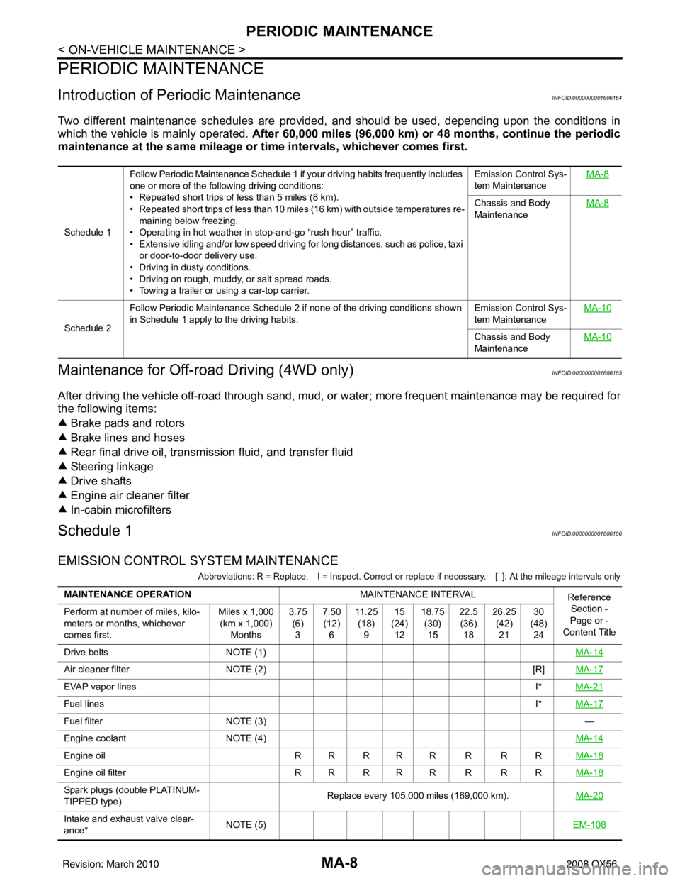
EMISSION CONTROL SYSTEM MAINTENANCE
Abbreviations: R = Replace. I = Inspect. Correct or r eplace if necessary. [ ]: At the mileage intervals only
Schedule 1Follow Periodic Maintenance Schedule 1 if your driving habits frequently includes
one or more of the following driving conditions:
• Repeated short trips of less than 5 miles (8 km).
• Repeated short trips of less than 10 miles (16 km) with outside temperatures re-
maining below freezing.
• Operating in hot weather in stop-and-go “rush hour” traffic.
• Extensive idling and/or low speed driving for long distances, such as police, taxi
or door-to-door delivery use.
• Driving in dusty conditions.
• Driving on rough, muddy, or salt spread roads.
• Towing a trailer or using a car-top carrier. Emission Control Sys-
tem Maintenance
MA-8
Chassis and Body
Maintenance
MA-8
Schedule 2Follow Periodic Maintenance Schedule 2 if none of the driving conditions shown
in Schedule 1 apply to the driving habits.
Emission Control Sys-
tem MaintenanceMA-10Chassis and Body
Maintenance
MA-10
MAINTENANCE OPERATION
MAINTENANCE INTERVAL
Reference
Section -
Page or -
Content Title
Perform at number of miles, kilo-
meters or months, whichever
comes first. Miles x 1,000
(km x 1,000) Months 3.75
(6)3 7.50
(12) 6 11 . 2 5
(18) 9 15
(24) 12 18.75
(30)15 22.5
(36) 18 26.25
(42)21 30
(48) 24
Drive belts NOTE (1) MA-14
Air cleaner filterNOTE (2) [R]MA-17
EVAP vapor lines I*MA-21
Fuel lines I*MA-17
Fuel filter NOTE (3) —
Engine coolant NOTE (4) MA-14
Engine oilR R R R R R R R MA-18
Engine oil filterR R R R R R R R MA-18
Spark plugs (double PLATINUM-
TIPPED type)Replace every 105,000 miles (169,000 km).
MA-20
Intake and exhaust valve clear-
ance*NOTE (5)
EM-108
Revision: March 2010 2008 QX56
Page 2611 of 4083

RECOMMENDED FLUIDS AND LUBRICANTSMA-13
< ON-VEHICLE MAINTENANCE >
C
DE
F
G H
I
J
K L
M B
MA
N
O A
NISSAN recommends the use of an energy conserving oil in order to
improve fuel economy. Select only
engine oils that meet the Ameri-
can Petroleum Institute (API) cert ification and International Lubricant
Standardization and Approval Committee (ILSAC) certification and
SAE viscosity standard (2). These oils have the API certification
mark (1) on the front of the container. Oils which do not have the
specified quality label should not be used as they could cause
engine damage.
Anti-Freeze Coolant Mixture RatioINFOID:0000000006211817
The engine cooling system is filled at the factory with a high-quality, year-round, anti-freeze coolant solution.
The anti-freeze solution contains rust and corrosion inhi bitors. Therefore, additional cooling system additives
are not necessary.
CAUTION:
• When adding or replacing coolant, be sure to use only Genuine NISSAN Long Life Anti-freeze cool-
ant or equivalent with the proper mixture ratio of 50% anti-freeze and 50% demineralized water or
distilled water.
• Other types of coolant solutions may damage your cooling system.
ALPIA0001ZZ
For outside temperatures down to: Anti-freeze coolant mixture ratio
° C ° F Genuine NISSAN Long Life An-
tifreeze coolant Demineralized water or distilled wa-
ter
– 35° – 30° 50 % 50 %
Revision: March 2010 2008 QX56
Page 2612 of 4083
MA-14
< ON-VEHICLE MAINTENANCE >
ENGINE MAINTENANCE
ENGINE MAINTENANCE
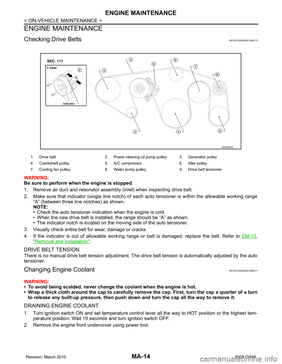
Checking Drive BeltsINFOID:0000000001606170
WARNING:
Be sure to perform when the engine is stopped.
1. Remove air duct and resonator assembly (inlet) when inspecting drive belt.
2. Make sure that indicator (single line notch) of each auto tensioner is within the allowable working range“A” (between three line notches) as shown.
NOTE:
• Check the auto tensioner indication when the engine is cold.
• When the new drive belt is installed, the range should be “A” as shown.
• The indicator notch is located on the moving side of the auto tensioner.
3. Visually check entire belt for wear, damage or cracks.
4. If the indicator is out of allowable working range or belt is damaged, replace the belt. Refer to EM-13,
"Removal and Installation".
DRIVE BELT TENSION
There is no manual drive belt tension adjustment. The driv e belt tension is automatically adjusted by the auto
tensioner.
Changing Engine CoolantINFOID:0000000001606171
WARNING:
• To avoid being scalded, never change the coolant when the engine is hot.
• Wrap a thick cloth around the cap to carefully remove the cap. First, turn the cap a quarter of a turn
to release any built-up pressure, th en push down and turn the cap all the way to remove it.
DRAINING ENGINE COOLANT
1. Turn ignition switch ON and set temperature control lever all the way to HOT position or the highest tem-
perature position. Wait 10 seconds and turn ignition switch OFF.
2. Remove the engine front undercover using power tool.
1. Drive belt 2. Power steering oil pump pulley 3. Generator pulley
4. Crankshaft pulley 5. A/C compressor6. Idler pulley
7. Cooling fan pulley 8. Water pump pulley 9. Drive belt tensioner
LBIA0391E
Revision: March 2010 2008 QX56
Page 2615 of 4083
ENGINE MAINTENANCEMA-17
< ON-VEHICLE MAINTENANCE >
C
DE
F
G H
I
J
K L
M B
MA
N
O A
2. Fill the radiator and the reservoir tank (to the “MAX”
line), with water. Reinstall the radiator cap and leave
the vented reservoir cap off.
3. Run the engine until it reaches normal operating temperature.
4. Press the engine accelerator two or three times under no-load.
5. Stop the engine and wait until it cools down.
6. Drain the water from the engine cooling system. Refer to CO-11, "
Changing Engine Coolant" .
7. Repeat steps 2 through 6 until clear water begins to drain from the radiator.
Checking Fuel LineINFOID:0000000001606172
Inspect the fuel lines and fuel tank for improper mounting, leaks,
cracks, damage, loose connections, chafing, or deterioration.
As necessary, repair or replace any faulty parts.
Changing Fuel FilterINFOID:0000000001606173
The fuel filter is part of the fuel level sensor unit, fuel filter and fuel pump assembly. Refer to FL-7, "Removal
and Installation" .
WARNING:
Before replacing the fuel filter, release the fuel pressure from the fuel system. Refer to EC-494, "
Fuel
Pressure Check".
Changing Engine Air Cleaner FilterINFOID:0000000001606174
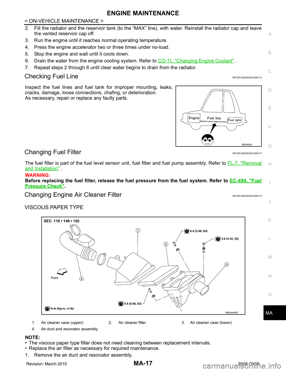
VISCOUS PAPER TYPE
NOTE:
• The viscous paper type filter does not need cleaning between replacement intervals.
• Replace the air filter as necessary for required maintenance.
1. Remove the air duct and resonator assembly.
SMA803A
1. Air cleaner case (upper) 2. Air cleaner filter3. Air cleaner case (lower)
4. Air duct and resonator assembly
WBIA0465E
Revision: March 2010 2008 QX56
Page 2646 of 4083
MWI
MWI-1
DRIVER INFORMATION & MULTIMEDIA
C
DE
F
G H
I
J
K L
M B
SECTION MWI
A
O P
CONTENTS
METER, WARNING LAMP & INDICATOR
BASIC INSPECTION ....... .............................4
DIAGNOSIS AND REPAIR WORKFLOW ..... .....4
Work Flow ........................................................... ......4
FUNCTION DIAGNOSIS ...............................5
METER SYSTEM ............................................ .....5
METER SYSTEM .........................................................5
METER SYSTEM : System Diagram ........................5
METER SYSTEM : System Description ....................5
METER SYSTEM : Arrangem ent of Combination
Meter ................................................................... ......
6
METER SYSTEM : Component Parts Location ........7
METER SYSTEM : Component Description ....... ......7
SPEEDOMETER ..........................................................8
SPEEDOMETER : System Diagram ................... ......8
SPEEDOMETER : System Description .....................8
SPEEDOMETER : Component Parts Location .........9
SPEEDOMETER : Component Description ........ ......9
TACHOMETER ...................................................... ......9
TACHOMETER : System Diagram ...........................9
TACHOMETER : System De scription .....................10
TACHOMETER : Component Parts Location ..... ....10
TACHOMETER : Component Description ..............10
ENGINE COOLANT TEMPERATURE GAUGE .... ....10
ENGINE COOLANT TEMPERATURE GAUGE :
System Diagram ......................................................
11
ENGINE COOLANT TEMPERATURE GAUGE :
System Description .................................................
11
ENGINE COOLANT TEMPERATURE GAUGE :
Component Parts Location ......................................
11
ENGINE COOLANT TEMPERATURE GAUGE :
Component Description ...........................................
12
FUEL GAUGE ........................................................ ....12
FUEL GAUGE : System Diagram ...........................12
FUEL GAUGE : System Description .......................12
FUEL GAUGE : Component Parts Location ...........12
FUEL GAUGE : Component Description ............. ....13
ENGINE OIL PRESSURE GAUGE ............................13
ENGINE OIL PRESSURE GAUGE : System Dia-
gram .................................................................... ....
13
ENGINE OIL PRESSURE GAUGE : System De-
scription ...................................................................
13
ENGINE OIL PRESSURE GAUGE : Component
Parts Location ..........................................................
14
ENGINE OIL PRESSURE GAUGE : Component
Description ...............................................................
14
VOLTAGE GAUGE ................................................ ....14
VOLTAGE GAUGE : System Diagram ....................15
VOLTAGE GAUGE : System Description ................15
VOLTAGE GAUGE : Component Parts Location ....15
VOLTAGE GAUGE : Component Description .........16
ODO/TRIP METER ................................................. ....16
ODO/TRIP METER : System Diagram ....................16
ODO/TRIP METER : System Description ................16
ODO/TRIP METER : Component Parts Location ....16
ODO/TRIP METER : Component Description .........17
SHIFT POSITION INDICATOR .............................. ....17
SHIFT POSITION INDICATOR : System Diagram ....17
SHIFT POSITION INDICATOR : System Descrip-
tion ...........................................................................
17
SHIFT POSITION INDICATOR : Component
Parts Location ..........................................................
18
SHIFT POSITION INDICATOR : Component De-
scription ............................................................... ....
18
WARNING LAMPS/INDICATOR LAMPS .............. ....18
WARNING LAMPS/INDICATOR LAMPS : System
Diagram ............................................................... ....
18
WARNING LAMPS/INDICATOR LAMPS : System
Description ........................................................... ....
19
WARNING LAMPS/INDICATOR LAMPS : Com-
ponent Parts Location ..............................................
19
WARNING LAMPS/INDICATOR LAMPS : Com-
ponent Description ...................................................
19
Revision: March 2010 2008 QX56
Page 2650 of 4083
MWI
METER SYSTEMMWI-5
< FUNCTION DIAGNOSIS >
C
DE
F
G H
I
J
K L
M B A
O P
FUNCTION DIAGNOSIS
METER SYSTEM
METER SYSTEM
METER SYSTEM : System DiagramINFOID:0000000001691233
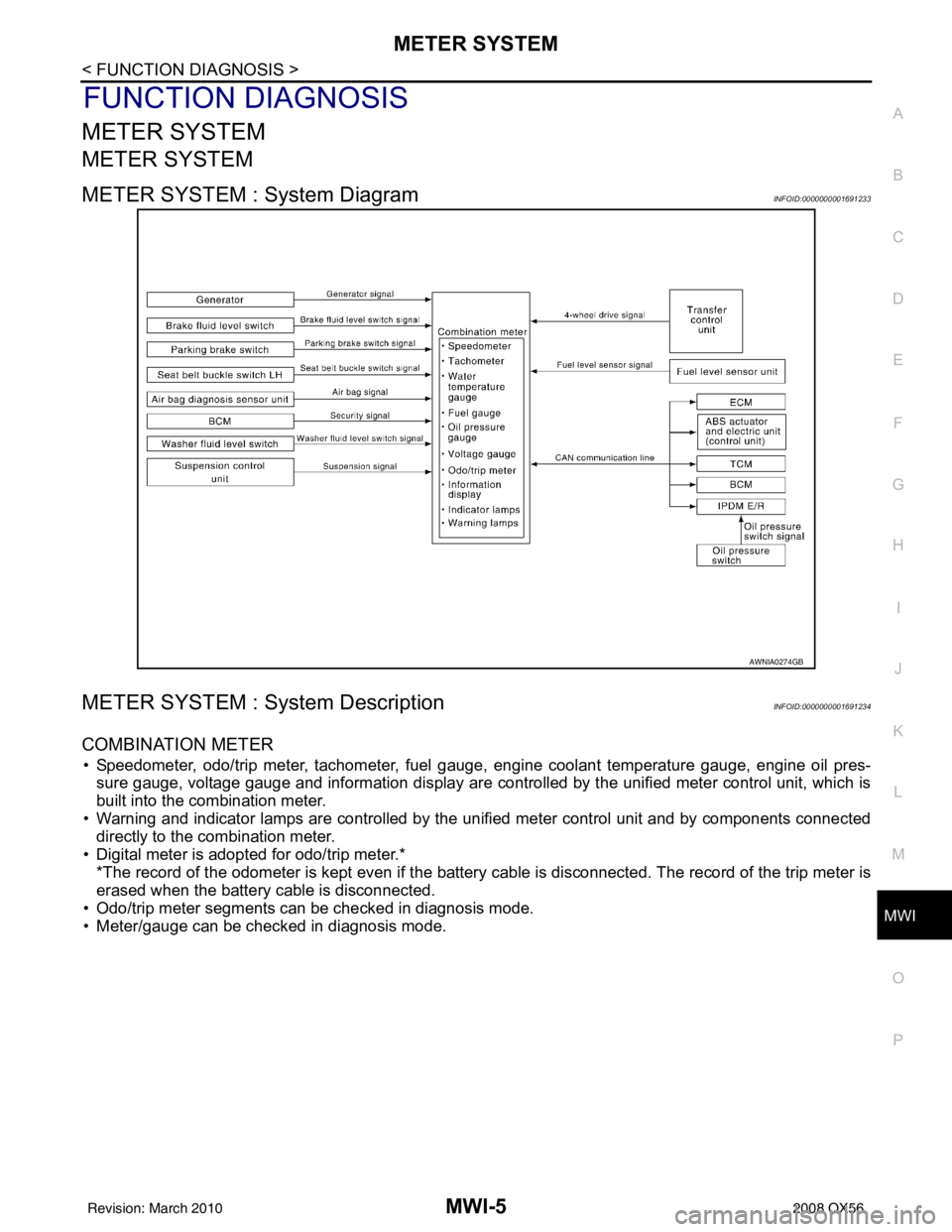
METER SYSTEM : System DescriptionINFOID:0000000001691234
COMBINATION METER
• Speedometer, odo/trip meter, tachometer, fuel gauge, engine coolant temperature gauge, engine oil pres-
sure gauge, voltage gauge and information display are controlled by the unified meter control unit, which is
built into the combination meter.
• Warning and indicator lamps are controlled by the unified meter control unit and by components connected directly to the combination meter.
• Digital meter is adopted for odo/trip meter.* *The record of the odometer is kept even if the battery cable is disconnected. The record of the trip meter is
erased when the battery cable is disconnected.
• Odo/trip meter segments can be checked in diagnosis mode.
• Meter/gauge can be checked in diagnosis mode.
AWNIA0274GB
Revision: March 2010 2008 QX56
Page 2652 of 4083
MWI
METER SYSTEMMWI-7
< FUNCTION DIAGNOSIS >
C
DE
F
G H
I
J
K L
M B A
O P
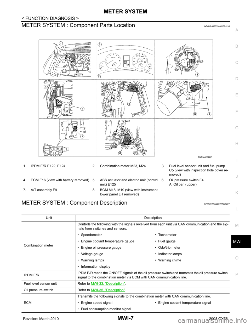
METER SYSTEM : Com ponent Parts LocationINFOID:0000000001691236
METER SYSTEM : Component DescriptionINFOID:0000000001691237
1. IPDM E/R E122, E124 2. Combination meter M23, M24 3. Fuel level sensor unit and fuel pump
C5 (view with inspection hole cover re-
moved)
4. ECM E16 (view with battery removed) 5. ABS actuator and electric unit (control unit) E1256. Oil pressure switch F4
A: Oil pan (upper)
7. A/T assembly F9 8. BCM M18, M19 (view with instrument
lower panel LH removed)
AWNIA0201ZZ
Unit Description
Combination meter Controls the following with the signals received from each unit via CAN communication and the sig-
nals from switches and sensors.
• Speedometer
• Tachometer
• Engine coolant temperature gauge • Fuel gauge
• Engine oil pressure gauge • Odo/trip meter
• Voltage gauge • Indicator lamps
• Warning lamps • Warning chime
• Information display
IPDM E/R IPDM E/R reads the ON/OFF signals of the oil pressure switch and transmits the oil pressure switch
signal to the combination meter via BCM with CAN communication line.
Fuel level sensor unit Refer to MWI-33, "
Description".
Oil pressure switch Refer to MWI-35, "
Description".
ECM Transmits the following signals to the combination meter with CAN communication line.
• Engine speed signal
• Engine coolant temperature signal
• Fuel consumption monitor signal
Revision: March 2010 2008 QX56
Page 2655 of 4083
MWI-10
< FUNCTION DIAGNOSIS >
METER SYSTEM
TACHOMETER : System Description
INFOID:0000000001691243
The tachometer indicates engine speed in revolutions per minute (rpm).
The ECM provides an engine speed signal to the co mbination meter via CAN communication lines.
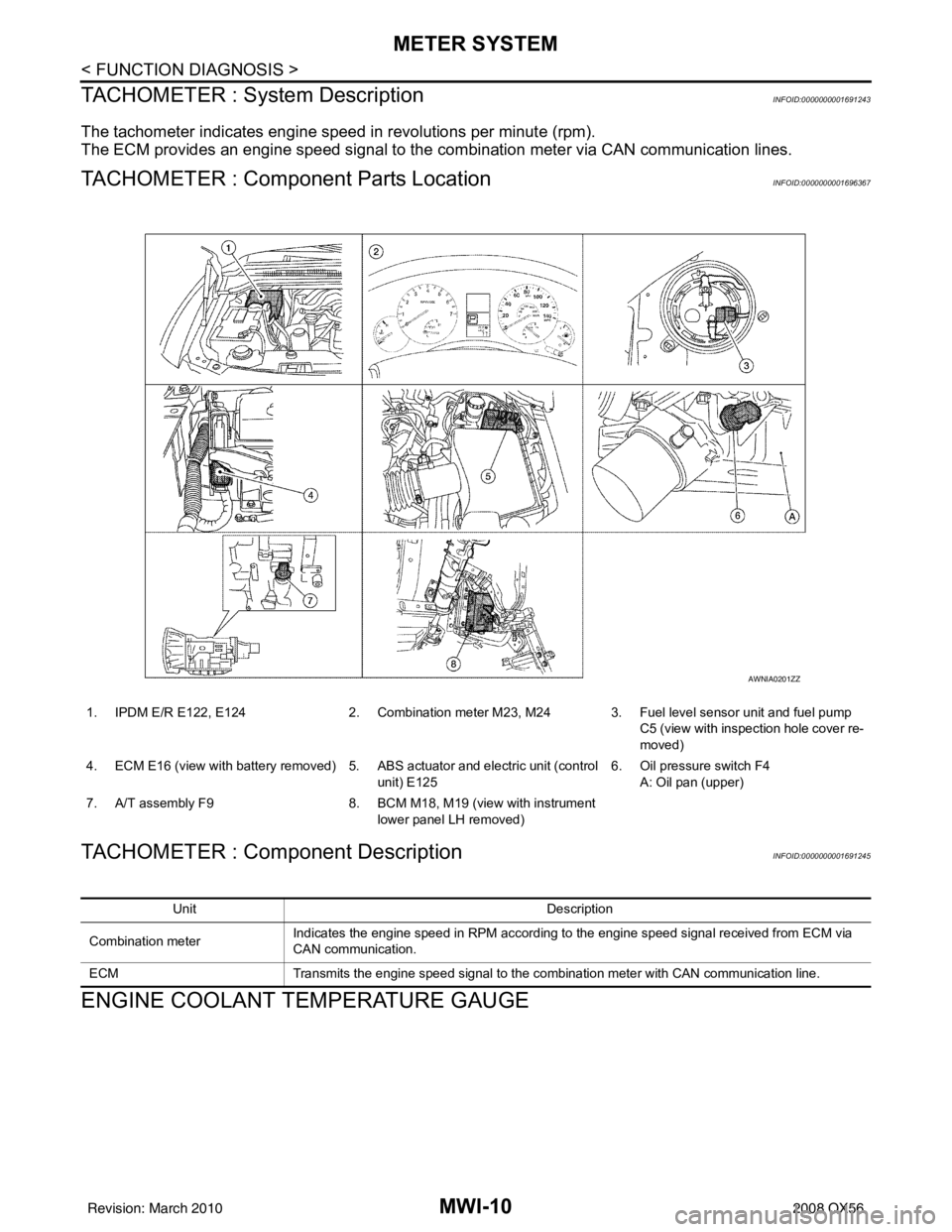
TACHOMETER : Component Parts LocationINFOID:0000000001696367
TACHOMETER : Component DescriptionINFOID:0000000001691245
ENGINE COOLANT TEMPERATURE GAUGE
1. IPDM E/R E122, E1242. Combination meter M23, M24 3. Fuel level sensor unit and fuel pump
C5 (view with inspection hole cover re-
moved)
4. ECM E16 (view with battery removed) 5. ABS actuator and electric unit (control
unit) E125 6. Oil pressure switch F4
A: Oil pan (upper)
7. A/T assembly F9 8. BCM M18, M19 (view with instrument
lower panel LH removed)
AWNIA0201ZZ
Unit Description
Combination meter Indicates the engine speed in RPM according to the engine speed signal received from ECM via
CAN communication.
ECM Transmits the engine speed signal to the combination meter with CAN communication line.
Revision: March 2010 2008 QX56