2008 INFINITI FX35 drain bolt
[x] Cancel search: drain boltPage 2815 of 3924
FFD-24
< SERVICE INFORMATION >
FRONT FINAL DRIVE ASSEMBLY
b. If the runout value is still outside of the limit after the phase has been changed, possible cause will be an
assembly malfunction of drive pinion and pinion bearing and malfunction of pinion bearing. Check for
these items and repair if necessary.
c. If the runout value is still outside of the limit after the check and repair, replace companion flange.
DISASSEMBLY
Side Shaft Assembly
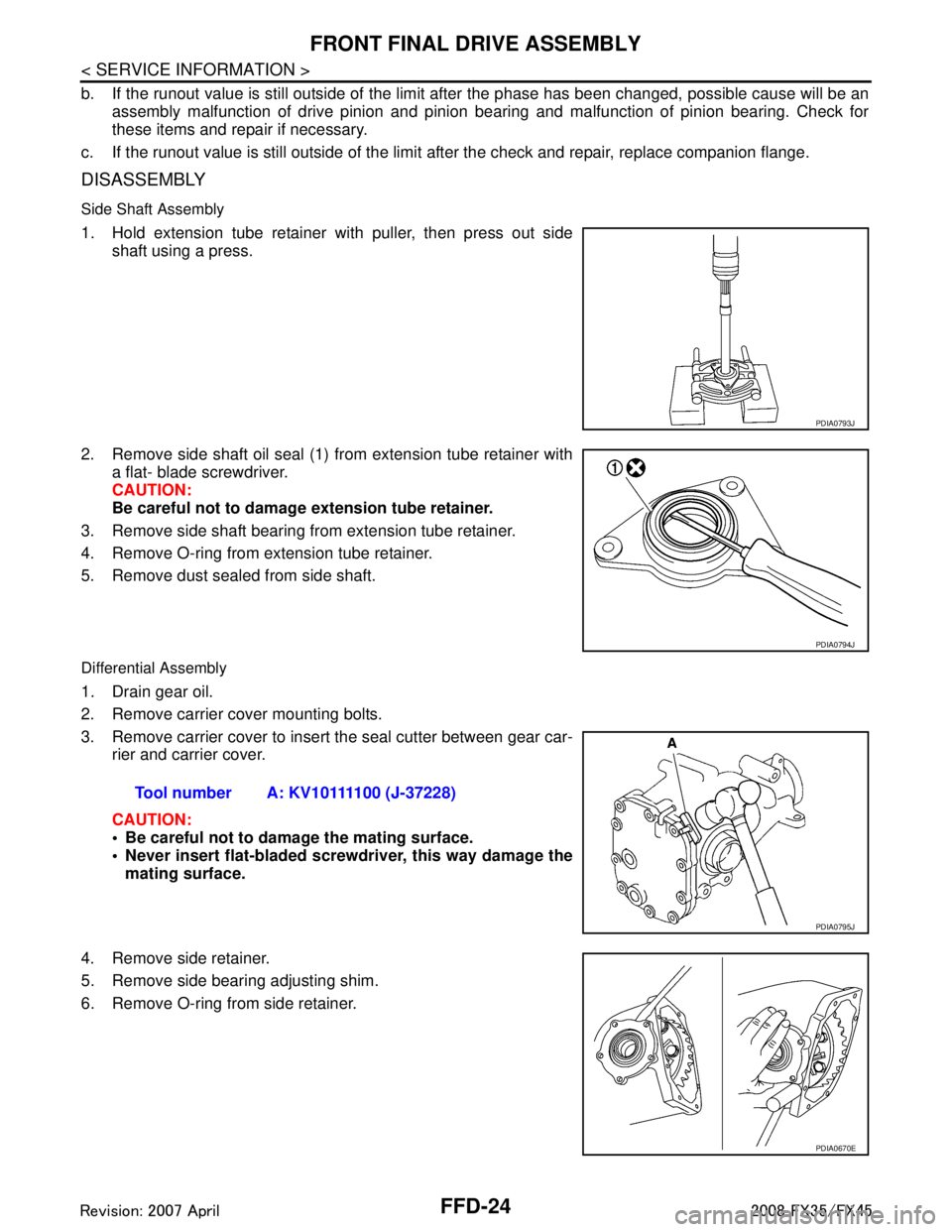
1. Hold extension tube retainer with puller, then press out side shaft using a press.
2. Remove side shaft oil seal (1) from extension tube retainer with a flat- blade screwdriver.
CAUTION:
Be careful not to damage extension tube retainer.
3. Remove side shaft bearing from extension tube retainer.
4. Remove O-ring from extension tube retainer.
5. Remove dust sealed from side shaft.
Differential Assembly
1. Drain gear oil.
2. Remove carrier cover mounting bolts.
3. Remove carrier cover to insert the seal cutter between gear car- rier and carrier cover.
CAUTION:
Be careful not to damage the mating surface.
Never insert flat-bladed screwdriver, this way damage the
mating surface.
4. Remove side retainer.
5. Remove side bearing adjusting shim.
6. Remove O-ring from side retainer.
PDIA0793J
PDIA0794J
Tool number A: KV10111100 (J-37228)
PDIA0795J
PDIA0670E
3AA93ABC3ACD3AC03ACA3AC03AC63AC53A913A773A893A873A873A8E3A773A983AC73AC93AC03AC3
3A893A873A873A8F3A773A9D3AAF3A8A3A8C3A863A9D3AAF3A8B3A8C
Page 3298 of 3924
![INFINITI FX35 2008 Service Manual
OIL COOLERLU-13
< SERVICE INFORMATION > [VQ35DE]
C
D
E
F
G H
I
J
K L
M A
LU
NP
O
AWD models
Removal and InstallationINFOID:0000000001325819
REMOVAL
WARNING:
Be careful not to get burn yourself, as en INFINITI FX35 2008 Service Manual
OIL COOLERLU-13
< SERVICE INFORMATION > [VQ35DE]
C
D
E
F
G H
I
J
K L
M A
LU
NP
O
AWD models
Removal and InstallationINFOID:0000000001325819
REMOVAL
WARNING:
Be careful not to get burn yourself, as en](/manual-img/42/57017/w960_57017-3297.png)
OIL COOLERLU-13
< SERVICE INFORMATION > [VQ35DE]
C
D
E
F
G H
I
J
K L
M A
LU
NP
O
AWD models
Removal and InstallationINFOID:0000000001325819
REMOVAL
WARNING:
Be careful not to get burn yourself, as en
gine oil and engine coolant may be hot.
NOTE:
When removing oil cooler only, step 2 is unnecessary.
1. Remove front engine undercover with power tool.
2. Drain engine coolant from radiator and cylinder block. Refer to CO-10, "
Changing Engine Coolant" and
EM-123, "
Disassembly and Assembly".
NOTE:
Perform this step when removing water pipes.
3. Disconnect water hoses from oil cooler. When removing oil cooler only, pinching water hoses near oil cooler to prevent engine coolant from spill-
ing out.
Remaining engine coolant in piping will come out. Use a tray to collect it.
CAUTION:
Perform this step when the engine is cold.
Do not spill engine coolant on drive belts.
4. Using oil filter wrench [SST: KV10115801 (J38956)], remove oil filter. Refer to LU-8, "
Removal and Instal-
lation".
CAUTION:
Do not spill engine oil on drive belts.
5. Remove connector bolt, and remove oil cooler. CAUTION:
Do not spill engine oil to rubber parts such as drive belts and engine mounting insulator.
SBIA0584E
1. Oil filter 2. Connector bolt 3. Oil cooler
4. O-ring 5. Relief valve 6. Oil filter bracket
7. Water hose 8. Water hose 9. Water pipe
10. Water hose
3AA93ABC3ACD3AC03ACA3AC03AC63AC53A913A773A893A873A873A8E3A773A983AC73AC93AC03AC3
3A893A873A873A8F3A773A9D3AAF3A8A3A8C3A863A9D3AAF3A8B3A8C
Page 3312 of 3924
![INFINITI FX35 2008 Service Manual
OIL COOLERLU-27
< SERVICE INFORMATION > [VK45DE]
C
D
E
F
G H
I
J
K L
M A
LU
NP
O
OIL COOLER
ComponentINFOID:0000000001325832
Removal and InstallationINFOID:0000000001325833
WARNING:
Be careful not to INFINITI FX35 2008 Service Manual
OIL COOLERLU-27
< SERVICE INFORMATION > [VK45DE]
C
D
E
F
G H
I
J
K L
M A
LU
NP
O
OIL COOLER
ComponentINFOID:0000000001325832
Removal and InstallationINFOID:0000000001325833
WARNING:
Be careful not to](/manual-img/42/57017/w960_57017-3311.png)
OIL COOLERLU-27
< SERVICE INFORMATION > [VK45DE]
C
D
E
F
G H
I
J
K L
M A
LU
NP
O
OIL COOLER
ComponentINFOID:0000000001325832
Removal and InstallationINFOID:0000000001325833
WARNING:
Be careful not to get burn yourself, as
engine oil and engine coolant are hot.
REMOVAL
NOTE:
When removing oil cooler only, step 2 is unnecessary.
1. Remove front engine undercover with power tool.
2. Drain engine coolant from radiator and cylinder block. Refer to CO-37, "
Changing Engine Coolant" and
EM-241, "
Component".
NOTE:
Perform this step when removing water pipe.
3. Remove oil filter. Refer to LU-26, "
Removal and Installation".
CAUTION:
Do not spill engine oil on drive belts.
4. Disconnect water hoses from oil cooler. When removing oil cooler only, pinching water hoses near oil cooler to prevent engine coolant spilling.
CAUTION:
Perform this step when engine is cold.
Do not spill engine coolant on the drive belt.
5. Remove connector bolt, and remove oil cooler. CAUTION:
Do not spill engine oil to rubber parts such as drive belts and engine mounting insulator.
1. Oil filter 2. Connector bolt 3. Water hose
4. Water pipe 5. Oil cooler 6. O-ring
7. Oil pan (left side) 8. Water hose 9. Relief valve
PBIC2977E
3AA93ABC3ACD3AC03ACA3AC03AC63AC53A913A773A893A873A873A8E3A773A983AC73AC93AC03AC3
3A893A873A873A8F3A773A9D3AAF3A8A3A8C3A863A9D3AAF3A8B3A8C
Page 3329 of 3924
MA-12
< SERVICE INFORMATION >
ENGINE MAINTENANCE (VQ35DE ENGINE)
When belt is replaced with a new one, adjust it to value for “New belt” to accommodate for insuffi-
cient adaptability with pulley grooves.
When deflection or tension of belt being used exceeds “Limit”, adjust it to value for “After adjust-
ment”.
When checking belt deflection or te nsion immediately after installation, first adjust it to the specified
value. Then, after turning crankshaft two turns or mo re, re-adjust to the specified value to avoid vari-
ation in deflection between pulleys.
When installing belt, make sure that it is correctly engaged with pulley grooves.
Keep engine oil, working fluid and engine coolant away from belt and pulley grooves.
Do not twist or bend belt excessively.
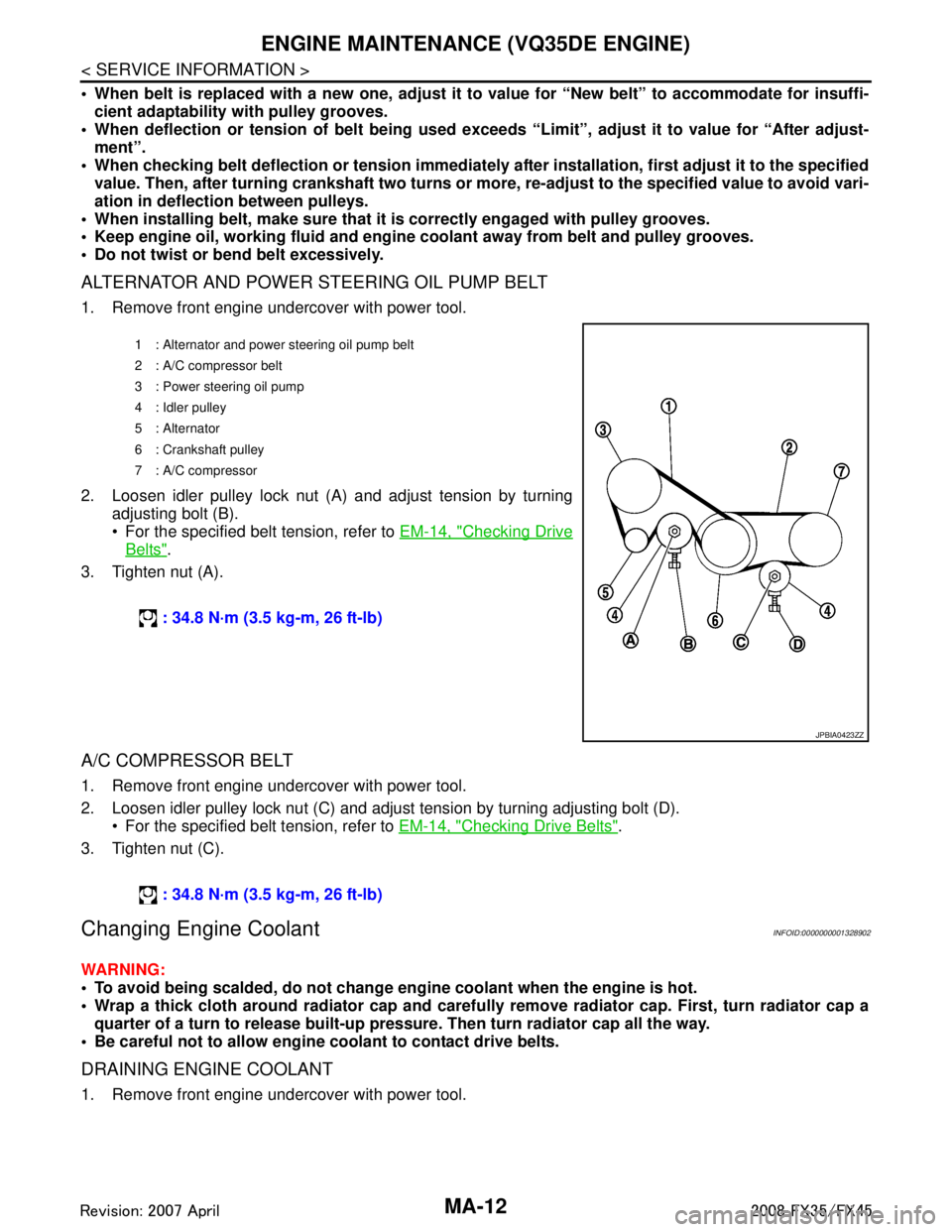
ALTERNATOR AND POWER STEERING OIL PUMP BELT
1. Remove front engine undercover with power tool.
2. Loosen idler pulley lock nut (A) and adjust tension by turning adjusting bolt (B).
For the specified belt tension, refer to EM-14, "
Checking Drive
Belts".
3. Tighten nut (A).
A/C COMPRESSOR BELT
1. Remove front engine undercover with power tool.
2. Loosen idler pulley lock nut (C) and adjust tension by turning adjusting bolt (D). For the specified belt tension, refer to EM-14, "
Checking Drive Belts".
3. Tighten nut (C).
Changing Engine CoolantINFOID:0000000001328902
WARNING:
To avoid being scalded, do not change en gine coolant when the engine is hot.
Wrap a thick cloth around radiator cap and carefully remove radiator cap. First, turn radiator cap a
quarter of a turn to release built-up pressu re. Then turn radiator cap all the way.
Be careful not to allow engine coolant to contact drive belts.
DRAINING ENGINE COOLANT
1. Remove front engine undercover with power tool.
1 : Alternator and power steering oil pump belt
2: A/C compressor belt
3 : Power steering oil pump
4 : Idler pulley
5 : Alternator
6 : Crankshaft pulley
7: A/C compressor
: 34.8 N·m (3.5 kg-m, 26 ft-lb)
JPBIA0423ZZ
: 34.8 N·m (3.5 kg-m, 26 ft-lb)
3AA93ABC3ACD3AC03ACA3AC03AC63AC53A913A773A893A873A873A8E3A773A983AC73AC93AC03AC3
3A893A873A873A8F3A773A9D3AAF3A8A3A8C3A863A9D3AAF3A8B3A8C
Page 3345 of 3924
MA-28
< SERVICE INFORMATION >
CHASSIS AND BODY MAINTENANCE
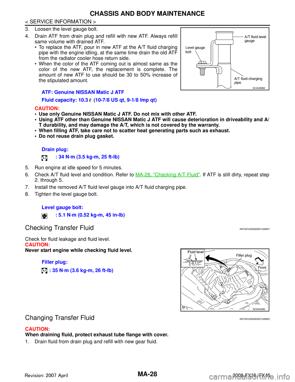
3. Loosen the level gauge bolt.
4. Drain ATF from drain plug and refill with new ATF. Always refillsame volume with drained ATF.
To replace the ATF, pour in new ATF at the A/T fluid charging
pipe with the engine idling, at the same time drain the old ATF
from the radiator cooler hose return side.
When the color of the ATF coming out is almost same as the color of the new ATF, the replacement is complete. The
amount of new ATF to use should be 30 to 50% increase of
the stipulated amount.
CAUTION:
Use only Genuine NISSAN Matic J ATF. Do not mix with other ATF.
Using ATF other than Genuine NISSAN Matic J AT F will cause deterioration in driveability and A/
T durability, and may damage the A/T, which is not covered by the warranty.
When filling ATF, take care not to scatter heat generating parts such as exhaust.
Do not reuse drain plug gasket.
5. Run engine at idle speed for 5 minutes.
6. Check A/T fluid level and condition. Refer to MA-26, "
Checking A/T Fluid". If ATF is still dirty, repeat step
2. through 5.
7. Install the removed A/T fluid level gauge into A/T fluid charging pipe.
8. Tighten the level gauge bolt.
Checking Transfer FluidINFOID:0000000001328921
Check for fluid leakage and fluid level.
CAUTION:
Never start engine while checking fluid level.
Changing Transfer FluidINFOID:0000000001328922
CAUTION:
When draining fluid, protect exh aust tube flange with cover.
1. Drain fluid from drain plug and refill with new gear fluid. ATF: Genuine NISSAN Matic J ATF
Fluid capacity: 10.3 (10-7/8 US qt, 9-1/8 lmp qt)
Drain plug:
: 34 N·m (3.5 kg-m, 25 ft-lb)
Level gauge bolt: : 5.1 N·m (0.52 kg-m, 45 in-lb)
SCIA4896E
Filler plug:
: 35 N·m (3.6 kg-m, 26 ft-lb)
SDIA2028E
3AA93ABC3ACD3AC03ACA3AC03AC63AC53A913A773A893A873A873A8E3A773A983AC73AC93AC03AC3
3A893A873A873A8F3A773A9D3AAF3A8A3A8C3A863A9D3AAF3A8B3A8C
Page 3473 of 3924
PS-18
< SERVICE INFORMATION >
POWER STEERING GEAR AND LINKAGE
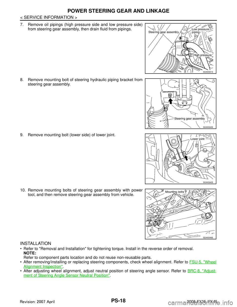
7. Remove oil pipings (high pressure side and low pressure side)from steering gear assembly, then drain fluid from pipings.
8. Remove mounting bolt of steering hydraulic piping bracket from steering gear assembly.
9. Remove mounting bolt (lower side) of lower joint.
10. Remove mounting bolts of steering gear assembly with power tool, and then remove steering gear assembly from vehicle.
INSTALLATION
Refer to "Removal and Installation" for tightening torque. Install in the reverse order of removal.
NOTE:
Refer to component parts location and do not reuse non-reusable parts.
After removing/installing or replacing steering components, check wheel alignment. Refer to FSU-5, "
Wheel
Alignment Inspection".
After adjusting wheel alignment, adjust neutral position of steering angle sensor. Refer to BRC-8, "
Adjust-
ment of Steering Angle Sensor Neutral Position".
SGIA0541E
SGIA0545E
SGIA0542E
SGIA0546E
3AA93ABC3ACD3AC03ACA3AC03AC63AC53A913A773A893A873A873A8E3A773A983AC73AC93AC03AC3
3A893A873A873A8F3A773A9D3AAF3A8A3A8C3A863A9D3AAF3A8B3A8C
Page 3483 of 3924
PS-28
< SERVICE INFORMATION >
POWER STEERING OIL PUMP
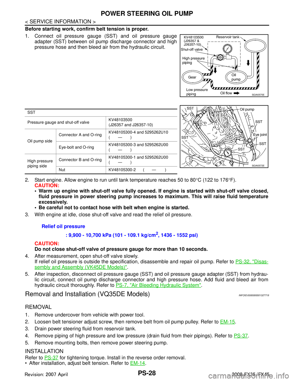
Before starting work, confirm belt tension is proper.
1. Connect oil pressure gauge (SST) and oil pressure gaugeadapter (SST) between oil pump discharge connector and high
pressure hose and then bleed air from the hydraulic circuit.
2. Start engine. Allow engine to run until tank temperature reaches 50 to 80 °C (122 to 176 °F).
CAUTION:
Warm up engine with shut-off val ve fully opened. If engine is started with shut-off valve closed,
fluid pressure in power steering pump increases to maximum. This will raise fluid temperature
excessively.
Be careful not to contact hose with belt when engine is started.
3. With engine at idle, close shut-off valve and read the relief oil pressure.
CAUTION:
Do not close shut-off valve of pressu re gauge for more than 10 seconds.
4. After measurement, open shut-off valve slowly. If relief oil pressure is outside the specification, disassemble and repair oil pump. Refer to PS-32, "
Disas-
sembly and Assembly (VK45DE Models)".
5. After inspection, disconnect oil pressure gauge (S ST) and oil pressure gauge adapter (SST) from hydrau-
lic circuit, connect oil pump discharge connector and high pressure hose. Add fluid and bleed air from
hydraulic circuit thoroughly. Refer to PS-7, "
Air Bleeding Hydraulic System".
Removal and Installation (VQ35DE Models)INFOID:0000000001327719
REMOVAL
1. Remove undercover from vehicle with power tool.
2. Loosen belt tensioner adjust screw, then remove belt from oil pump pulley. Refer to EM-15
.
3. Drain power steering fluid from reservoir tank.
4. Remove piping of high pressure and low pressure (drain fluid from their pipings). Refer to PS-37
.
5. Remove mounting bolts, then remove power steering pump.
INSTALLATION
Refer to PS-37 for tightening torque. Install in the reverse order removal.
After installation, adjust belt tension. Refer to EM-14
.
SGIA0570E
SST
Pressure gauge and shut-off valveKV48103500
(J26357 and J26357-10)
Oil pump side Connector A and O-ring
KV48105300-4 and 5295262U10
(—)
Eye-bolt and O-ring KV48105300-3 and 5295262U00
(—)
High pressure
piping side Connector B and O-ring
KV48105300-1 and 5295262U00
(—)
Nut KV48105300-2 ( — )
SGIA0572E
Relief oil pressure : 9,900 - 10,700 kPa (101 - 109.1 kg/cm
2, 1436 - 1552 psi)
3AA93ABC3ACD3AC03ACA3AC03AC63AC53A913A773A893A873A873A8E3A773A983AC73AC93AC03AC3
3A893A873A873A8F3A773A9D3AAF3A8A3A8C3A863A9D3AAF3A8B3A8C
Page 3484 of 3924
POWER STEERING OIL PUMPPS-29
< SERVICE INFORMATION >
C
DE
F
H I
J
K L
M A
B
PS
N
O P
After installation, bleed air. Refer to PS-7, "Air Bleeding Hydraulic System".
Removal and Installation (VK45DE Models)INFOID:0000000001327720
REMOVAL
1. Remove undercover from vehicle with power tool.
2. Remove power steering oil pump belt from auto tensioner. Refer to EM-170
.
3. Drain power steering fluid from reservoir tank.
4. Remove piping of high pressure and low pressure from power steering oil pump (drain fluid from their pip- ings). Refer to PS-37
.
5. Remove mounting bolts, then remove power steering pump.
INSTALLATION
Refer to PS-37 for tightening torque. Install in the reverse order removal.
After installation, bleed air. Refer to PS-7, "
Air Bleeding Hydraulic System".
NOTE:
Adjustment of belt tension is no necessary bec ause engine of this model equips auto tensioner.
Disassembly and Assembly (VQ35DE Models)INFOID:0000000001327721
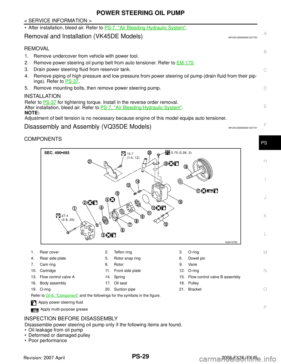
COMPONENTS
INSPECTION BEFORE DISASSEMBLY
Disassemble power steering oil pump only if the following items are found.
Oil leakage from oil pump
Deformed or damaged pulley
Poor performance
1. Rear cover 2. Teflon ring 3. O-ring
4. Rear side plate 5. Rotor snap ring 6. Dowel pin
7. Cam ring 8. Rotor 9. Vane
10. Cartridge 11. Front side plate 12. O-ring
13. Flow control valve A 14. Spring 15. Flow control valve B assembly
16. Body assembly 17. Oil seal 18. Pulley
19. O-ring 20. Suction pipe 21. Bracket
Refer to GI-8, "
Component" and the followings for the symbols in the figure.
: Apply power steering fluid
: Apply multi-purpose grease
SGIA1679E
3AA93ABC3ACD3AC03ACA3AC03AC63AC53A913A773A893A873A873A8E3A773A983AC73AC93AC03AC3
3A893A873A873A8F3A773A9D3AAF3A8A3A8C3A863A9D3AAF3A8B3A8C