2008 INFINITI FX35 high beam
[x] Cancel search: high beamPage 3160 of 3924

LT-58
< SERVICE INFORMATION >
AUTO LIGHT SYSTEM
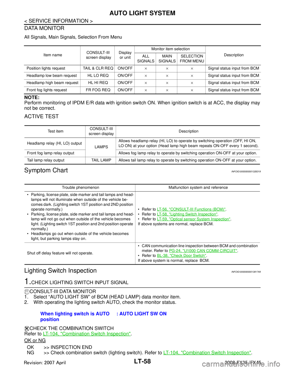
DATA MONITOR
All Signals, Main Signals, Selection From Menu
NOTE:
Perform monitoring of IPDM E/R data with ignition switch ON. When ignition switch is at ACC, the display may
not be correct.
ACTIVE TEST
Symptom ChartINFOID:0000000001328319
Lighting Switch InspectionINFOID:0000000001381749
1.CHECK LIGHTING SWITCH INPUT SIGNAL
CONSULT-III DATA MONITOR
1. Select “AUTO LIGHT SW” of BCM (HEAD LAMP) data monitor item.
2. With operating the lighting switch AUTO, check the monitor status.
CHECK THE COMBINATION SWITCH
Refer to LT-104, "
Combination Switch Inspection".
OK or NG
OK >> INSPECTION END
NG >> Check combination switch (lighting switch). Refer to LT-104, "
Combination Switch Inspection".
Item nameCONSULT-III
screen display Display
or unit Monitor item selection
Description
ALL
SIGNALS MAIN
SIGNALS SELECTION
FROM MENU
Position lights reques t TAIL & CLR REQ ON/OFF ×× ×Signal status input from BCM
Headlamp low beam request HL LO REQ ON/OFF ×× ×Signal status input from BCM
Headlamp high beam request HL HI REQ ON/OFF ×× ×Signal status input from BCM
Front fog lights request FR FOG REQ ON/OFF ×× ×Signal status input from BCM
Te s t i t e mCONSULT-III
screen display Description
Headlamp relay (HI, LO) output LAMPSAllows headlamp relay (HI, LO) to operate by switching operation (OFF, HI ON,
LO ON) at your option (Head lamp high beam repeats ON-OFF every 1 second).
Front fog lamp relay output Allows fog lamp relay to operate by switching operation ON-OFF at your option.
Tail lamp relay output TAIL LAMP Allows tail lamp relay to operate by switching operation ON-OFF at your option.
Trouble phenomenon Malfunction system and reference
Parking, license plate, side marker and tail lamps and head- lamps will not illuminate when outside of the vehicle be-
comes dark. (Lighting switch 1ST position and 2ND position
operate normally.)
Parking, license plate, side marker and tail lamps and head-
lamp will not go out when outside of the vehicle becomes
light. (Lighting switch 1ST position and 2nd position operate
normally.)
Headlamps go out when outside of the vehicle becomes light, but parking lamps stay on. Refer to
LT- 5 6 , "
CONSULT-III Functions (BCM)".
Refer to LT- 5 8 , "
Lighting Switch Inspection".
Refer to LT- 5 9 , "
Optical sensor System Inspection".
If above systems are normal, replace BCM.
Shut off delay feature will not operate. CAN communication line inspection between BCM and combination
meter. Refer to PG-24, "
U1000 CAN COMM CIRCUIT".
Refer to BL-38, "
Check Door Switch".
If above system is normal, replace BCM.
When lighting switch is AUTO
position : AUTO LIGHT SW ON
3AA93ABC3ACD3AC03ACA3AC03AC63AC53A913A773A893A873A873A8E3A773A983AC73AC93AC03AC3
3A893A873A873A8F3A773A9D3AAF3A8A3A8C3A863A9D3AAF3A8B3A8C
Page 3201 of 3924

COMBINATION SWITCHLT-99
< SERVICE INFORMATION >
C
DE
F
G H
I
J
L
M A
B
LT
N
O P
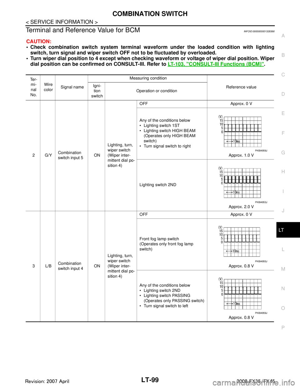
Terminal and Reference Value for BCMINFOID:0000000001328366
CAUTION:
Check combination switch system terminal wavef orm under the loaded condition with lighting
switch, turn signal and wipe r switch OFF not to be fluctuated by overloaded.
Turn wiper dial position to 4 except when checking w aveform or voltage of wiper dial position. Wiper
dial position can be confirmed on CONSULT-III. Refer to LT-103, "
CONSULT-III Functions (BCM)".
Te r -
mi-
nal
No. Wire
color Signal name Measuring condition
Reference value
Igni-
tion
switch Operation or condition
2G/Y Combination
switch input 5
ONLighting, turn,
wiper switch
(Wiper inter-
mittent dial po-
sition 4) OFF Approx. 0 V
Any of the conditions below
Lighting switch 1ST
Lighting switch HIGH BEAM
(Operates only HIGH BEAM
switch)
Turn signal switch to right
Approx. 1.0 V
Lighting switch 2ND Approx. 2.0 V
3L/B Combination
switch input 4 ONLighting, turn,
wiper switch
(Wiper inter-
mittent dial po-
sition 4) OFF Approx. 0 V
Front fog lamp switch
(Operates only front fog lamp
switch)
Approx. 0.8 V
Any of the conditions below
Lighting switch 2ND
Lighting switch PASSING (Operates only PASSING switch)
Turn signal switch to left
Approx. 0.8 V
PKIB4959J
PKIB4953J
PKIB4955J
PKIB4959J
3AA93ABC3ACD3AC03ACA3AC03AC63AC53A913A773A893A873A873A8E3A773A983AC73AC93AC03AC3
3A893A873A873A8F3A773A9D3AAF3A8A3A8C3A863A9D3AAF3A8B3A8C
Page 3204 of 3924

LT-102
< SERVICE INFORMATION >
COMBINATION SWITCH
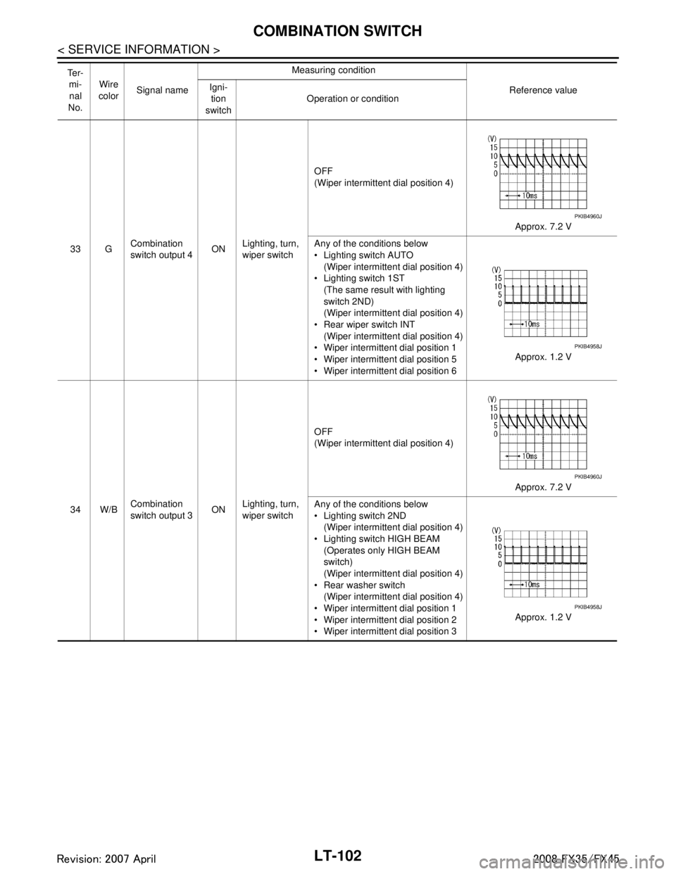
33 GCombination
switch output 4 ON
Lighting, turn,
wiper switch OFF
(Wiper intermittent dial position 4)
Approx. 7.2 V
Any of the conditions below
Lighting switch AUTO (Wiper intermittent dial position 4)
Lighting switch 1ST (The same result with lighting
switch 2ND)
(Wiper intermittent dial position 4)
Rear wiper switch INT (Wiper intermittent dial position 4)
Wiper intermittent dial position 1
Wiper intermittent dial position 5
Wiper intermittent dial position 6 Approx. 1.2 V
34 W/B Combination
switch output 3
ONLighting, turn,
wiper switch OFF
(Wiper intermittent dial position 4)
Approx. 7.2 V
Any of the conditions below
Lighting switch 2ND (Wiper intermittent dial position 4)
Lighting switch HIGH BEAM (Operates only HIGH BEAM
switch)
(Wiper intermittent dial position 4)
Rear washer switch
(Wiper intermittent dial position 4)
Wiper intermittent dial position 1
Wiper intermittent dial position 2
Wiper intermittent dial position 3 Approx. 1.2 V
Te r -
mi-nal
No. Wire
color Signal name Measuring condition
Reference value
Igni-
tion
switch Operation or condition
PKIB4960J
PKIB4958J
PKIB4960J
PKIB4958J
3AA93ABC3ACD3AC03ACA3AC03AC63AC53A913A773A893A873A873A8E3A773A983AC73AC93AC03AC3
3A893A873A873A8F3A773A9D3AAF3A8A3A8C3A863A9D3AAF3A8B3A8C
Page 3206 of 3924

LT-104
< SERVICE INFORMATION >
COMBINATION SWITCH
CONSULT-III BASIC OPERATION
Refer to GI-34, "Description".
DATA MONITOR
Display Item List
NOTE:
This item is displayed, but cannot be monitored
Combination Switch InspectionINFOID:0000000001381755
1.SYSTEM CHECK
Referring to table below, check which sy stem malfunctioning switch belongs to.
>> Check the system to which malfunctioning switch belongs, and then GO TO 2.
2.SYSTEM CHECK
CONSULT-III DATA MONITOR
1. Select “COMBI SW” of BCM data monitor item.
2. Confirm that other switches in malfunctioning system operate normally.
Monitor item Contents
TURN SIGNAL R “ON/OFF” Displays “Turn Ri ght (ON)/Other (OFF)” status, determined from lighting switch signal.
TURN SIGNAL L “ON/OFF” Displays “Turn Le ft (ON)/Other (OFF)” status, determined from lighting switch signal.
HI BEAM SW “ON/OFF” Displays status (high beam switch: ON/Others: OFF) of high beam switch judged from lighting switch
signal.
HEAD LAMP SW 1 “ON/OFF” Displays status (headlamp switch 2: ON/Others:
OFF) of headlamp switch 1 judged from lighting
switch signal.
HEAD LAMP SW 2 “ON/OFF” Displays status (headlamp switch 2: ON/Others:
OFF) of headlamp switch 2 judged from lighting
switch signal.
LIGHT SW 1ST “ON/OFF” Displays status (lighting switch 1ST or 2ND position: ON/Others: OFF) of lighting switch judged from
lighting switch signal.
PASSING SW “ON/OFF” Displays status (flash-to-pass switch: ON/Others: OFF) of flash-to-pass switch judged from lighting
switch signal.
AUTO LIGHT SW “ON/OFF” Displays “Auto light switch (ON)/Other (OFF)” status, determined from lighting switch signal.
FR FOG SW “ON/OFF” Displays “Fro nt fog lamp switch (ON)/Other (OFF)” status, determined from lighting switch signal.
RR FOG SW
NOTE“OFF” —
FR WIPER HI “ON/OFF” Disp lays “Front Wiper HI (ON)/Other (OFF)” stat us, determined from wiper switch signal.
FR WIPER LOW “ON/OFF” Displays “Front Wiper LOW (ON)/Oth er (OFF)” status, determined from wiper switch signal.
FR WIPER INT “ON/OFF” Displays “Front Wiper INT (ON)/Other (OFF)” status, determined from wiper switch signal.
FR WASHER SW “ON/OFF” Displays “Front Washer Switch (ON)/Other (OFF)” status, determined from wiper switch signal.
INT VOLUME “1 – 7” Displays intermittent operation knob setting (1 – 7), determined from wiper switch signal.
RR WIPER ON “ON/OFF” Displays “rear Wiper (ON)/Other (OFF)” status as judged from wiper switch signal.
RR WIPER INT “ON/OFF” Displays “rear Wiper INT (ON)/Other (OFF)” status as judged from wiper switch signal.
RR WASHER SW “ON/OFF” Displays “rear Washer Switch (ON)/Other (OFF)” status as judged from wiper switch signal.
System 1 System 2 System 3 System 4 System 5 — FR WASHER FR WIPER LO TURN LH TURN RH
FR WIPER HI — FR WIPER INT PASSING HEAD LAMP 1
INT VOLUME 1 RR WASHER — HEAD LAMP HI BEAM RR WIPER INT INT VOLUME 3 AUTO LIGHT — LIGHT SW 1
INT VOLUME 2 RR WIPER ON — FR FOG —
3AA93ABC3ACD3AC03ACA3AC03AC63AC53A913A773A893A873A873A8E3A773A983AC73AC93AC03AC3
3A893A873A873A8F3A773A9D3AAF3A8A3A8C3A863A9D3AAF3A8B3A8C