Page 3831 of 3924
TRANSFER ASSEMBLYTF-45
< SERVICE INFORMATION >
CEF
G H
I
J
K L
M A
B
TF
N
O P
16. Remove retainer from transfer assembly harness connector.
17. Remove transfer assembly harness connector from rear case.
18. Remove O-ring from transfer assembly harness connector.
19. Remove mainshaft assembly fr om rear case, using a drift.
20. Remove snap ring from rear case.
21. Remove rear bearing from rear case, using a drift.
22. Remove baffle plate from rear case.
23. Remove breather tube from rear case.
SDIA1597E
Tool number : ST33052000 ( — )
PDIA0262E
PDIA0263E
Tool number A: ST30611000 (J-25742-1) B: ST35321000 ( — )
PDIA0264E
SDIA1701E
3AA93ABC3ACD3AC03ACA3AC03AC63AC53A913A773A893A873A873A8E3A773A983AC73AC93AC03AC3
3A893A873A873A8F3A773A9D3AAF3A8A3A8C3A863A9D3AAF3A8B3A8C
Page 3832 of 3924

TF-46
< SERVICE INFORMATION >
TRANSFER ASSEMBLY
Mainshaft Assembly
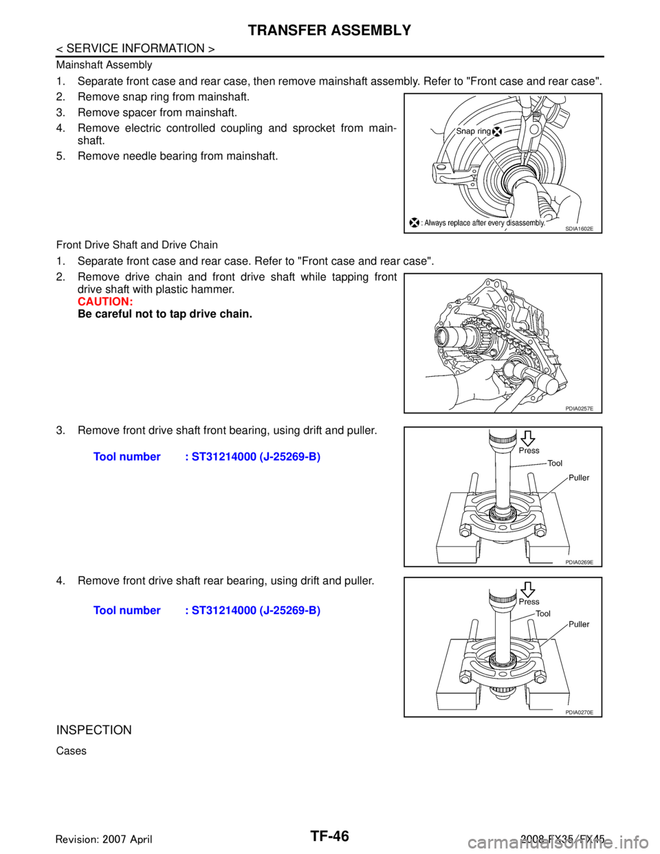
1. Separate front case and rear case, then remove mainshaft assembly. Refer to "Front case and rear case".
2. Remove snap ring from mainshaft.
3. Remove spacer from mainshaft.
4. Remove electric controlled coupling and sprocket from main-shaft.
5. Remove needle bearing from mainshaft.
Front Drive Shaft and Drive Chain
1. Separate front case and rear case. Refer to "Front case and rear case".
2. Remove drive chain and front drive shaft while tapping front drive shaft with plastic hammer.
CAUTION:
Be careful not to tap drive chain.
3. Remove front drive shaft front bearing, using drift and puller.
4. Remove front drive shaft rear bearing, using drift and puller.
INSPECTION
Cases
SDIA1602E
PDIA0257E
Tool number : ST31214000 (J-25269-B)
PDIA0269E
Tool number : ST31214000 (J-25269-B)
PDIA0270E
3AA93ABC3ACD3AC03ACA3AC03AC63AC53A913A773A893A873A873A8E3A773A983AC73AC93AC03AC3
3A893A873A873A8F3A773A9D3AAF3A8A3A8C3A863A9D3AAF3A8B3A8C
Page 3833 of 3924
TRANSFER ASSEMBLYTF-47
< SERVICE INFORMATION >
CEF
G H
I
J
K L
M A
B
TF
N
O P
Check items below. If necessary , replace them with new ones.
Contact surfaces of bearing for wear, damage, etc.
Damage and cracks of case.
Bearing
Check items below. If necessary , replace them with new ones.
Damage and rough rotation of bearing.
Shaft
Check items below. If necessa ry, replace them with new one.
Damage, peeling, dent, uneven wear, bending, etc. of shaft.
Gears and Chain
Check items below. If necessary , replace them with new ones.
Excessive wear, damage, peeling, etc. of gear and chain.
ASSEMBLY
Front Drive Shaft and Drive Chain
PDIA0293E
PDIA0300E
PDIA0294E
SDIA2365E
3AA93ABC3ACD3AC03ACA3AC03AC63AC53A913A773A893A873A873A8E3A773A983AC73AC93AC03AC3
3A893A873A873A8F3A773A9D3AAF3A8A3A8C3A863A9D3AAF3A8B3A8C
Page 3834 of 3924

TF-48
< SERVICE INFORMATION >
TRANSFER ASSEMBLY
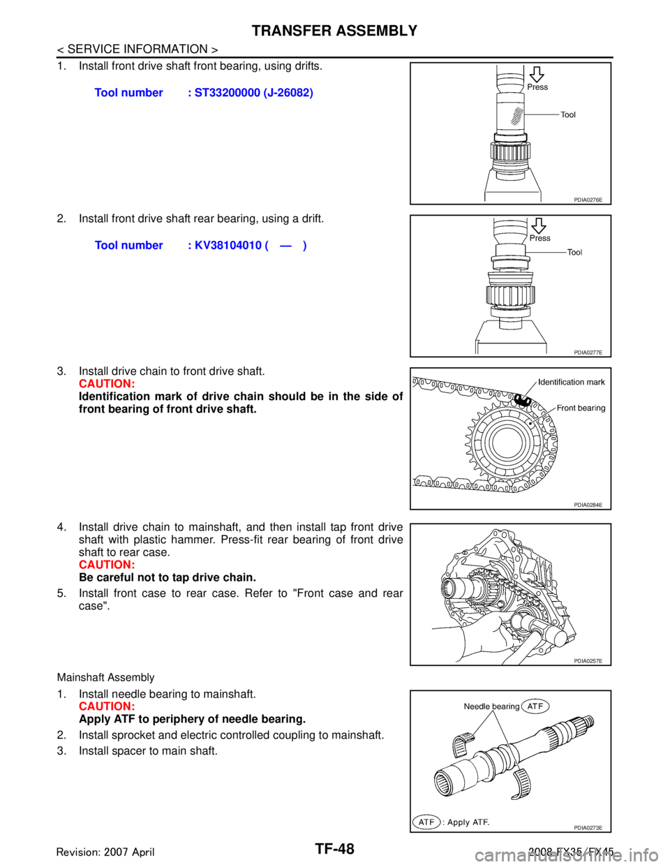
1. Install front drive shaft front bearing, using drifts.
2. Install front drive shaft rear bearing, using a drift.
3. Install drive chain to front drive shaft.CAUTION:
Identification mark of drive ch ain should be in the side of
front bearing of front drive shaft.
4. Install drive chain to mainshaft, and then install tap front drive shaft with plastic hammer. Press-fit rear bearing of front drive
shaft to rear case.
CAUTION:
Be careful not to tap drive chain.
5. Install front case to rear case. Refer to "Front case and rear case".
Mainshaft Assembly
1. Install needle bearing to mainshaft.CAUTION:
Apply ATF to periphery of needle bearing.
2. Install sprocket and electric controlled coupling to mainshaft.
3. Install spacer to main shaft. Tool number : ST33200000 (J-26082)
PDIA0276E
Tool number : KV38104010 ( — )
PDIA0277E
PDIA0284E
PDIA0257E
PDIA0273E
3AA93ABC3ACD3AC03ACA3AC03AC63AC53A913A773A893A873A873A8E3A773A983AC73AC93AC03AC3
3A893A873A873A8F3A773A9D3AAF3A8A3A8C3A863A9D3AAF3A8B3A8C
Page 3835 of 3924
TRANSFER ASSEMBLYTF-49
< SERVICE INFORMATION >
CEF
G H
I
J
K L
M A
B
TF
N
O P
4. Install snap ring to mainshaft. CAUTION:
Do not reuse snap ring.
5. Install mainshaft assembly to rear case, then install front case and rear case. Refer to "Front case and rear case".
Front Case and Rear Case
1. Install breather tube, with plastic hammer.CAUTION:
Pay attention to the dir ection of breather tube.
2. Install baffle plate to rear case, and tighten bolt to the specified torque. Refer to "COMPONENTS".
3. Install rear bearing to rear case, using a drift. CAUTION:
Apply ATF to inside of rear bearing.
4. Install snap ring to rear case. CAUTION:
Do not reuse snap ring.
SDIA1602E
PDIA0274E
Tool number : KV38104010 ( — )
PDIA0275E
PDIA0263E
3AA93ABC3ACD3AC03ACA3AC03AC63AC53A913A773A893A873A873A8E3A773A983AC73AC93AC03AC3
3A893A873A873A8F3A773A9D3AAF3A8A3A8C3A863A9D3AAF3A8B3A8C
Page 3836 of 3924
TF-50
< SERVICE INFORMATION >
TRANSFER ASSEMBLY
5. Install mainshaft assembly to rear case, using a drift.CAUTION:
ATF should be applied to contact surface of mainshaft and
rear bearing.
6. Install O-ring to transfer assembly harness connector. CAUTION:
Do not reuse O-ring.
Apply ATF to O-ring.
7. Install transfer assembly harness connector into rear case.
8. Install retainer to transfer assembly harness connector.
9. Hold electric controlled coupling harness (1) with oil cover hold plate (2), install oil cover (3) to rear case (4), and tighten bolt to
the specified torque. Refer to "COMPONENTS".
CAUTION:
The harness should be gu ided by a cut portion.
10. Install oil gutter to rear case. CAUTION:
The tip of oil gutter should be put into rear case groove.Tool number : ST35321000 ( — )
SDIA2368E
SDIA1597E
SDIA3610E
PDIA0261E
3AA93ABC3ACD3AC03ACA3AC03AC63AC53A913A773A893A873A873A8E3A773A983AC73AC93AC03AC3
3A893A873A873A8F3A773A9D3AAF3A8A3A8C3A863A9D3AAF3A8B3A8C
Page 3837 of 3924

TRANSFER ASSEMBLYTF-51
< SERVICE INFORMATION >
CEF
G H
I
J
K L
M A
B
TF
N
O P
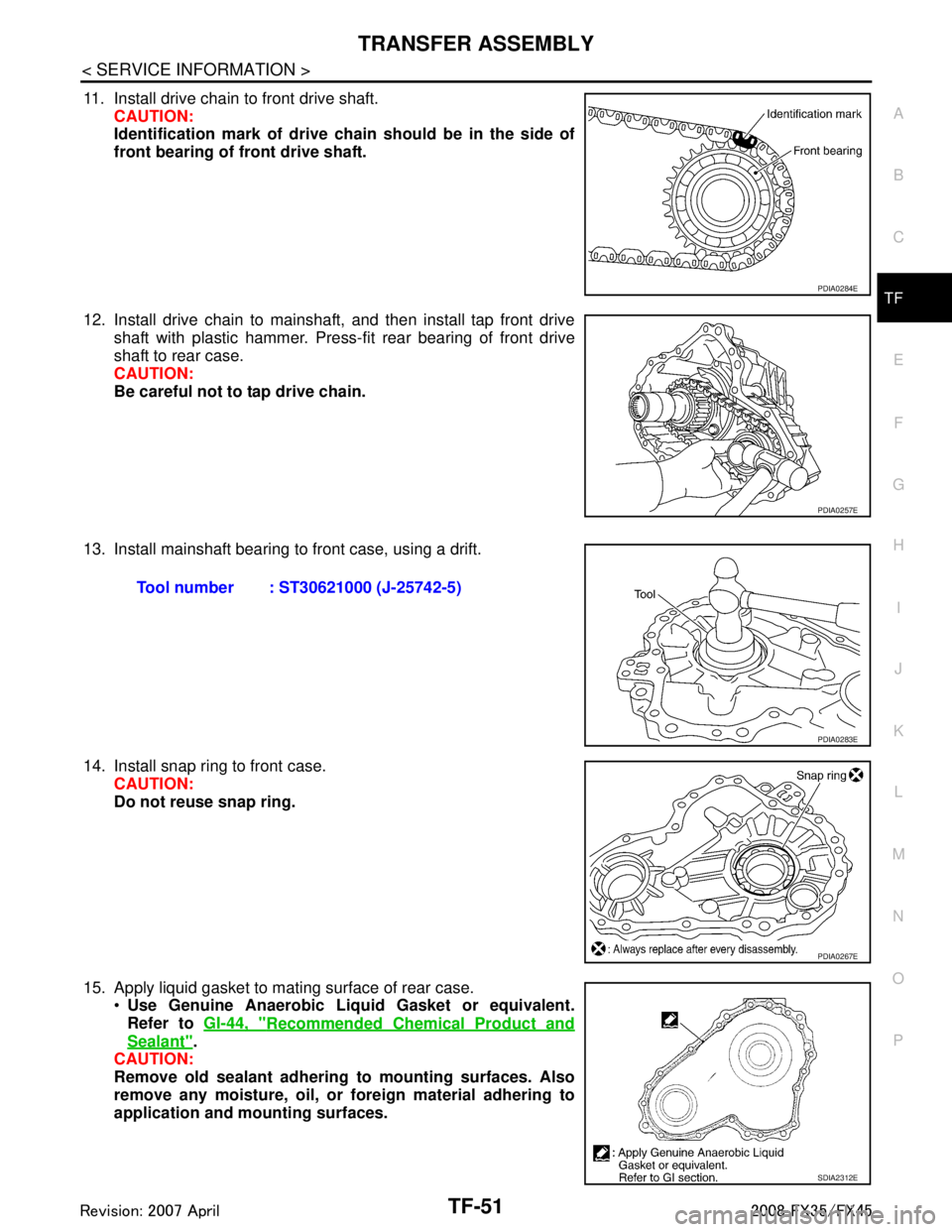
11. Install drive chain to front drive shaft. CAUTION:
Identification mark of drive ch ain should be in the side of
front bearing of front drive shaft.
12. Install drive chain to mainshaft, and then install tap front drive shaft with plastic hammer. Press-fit rear bearing of front drive
shaft to rear case.
CAUTION:
Be careful not to tap drive chain.
13. Install mainshaft bearing to front case, using a drift.
14. Install snap ring to front case. CAUTION:
Do not reuse snap ring.
15. Apply liquid gasket to mating surface of rear case. Use Genuine Anaerobic Liqu id Gasket or equivalent.
Refer to GI-44, "
Recommended Chemical Product and
Sealant".
CAUTION:
Remove old sealant adhering to mounting surfaces. Also
remove any moisture, oil, or foreign material adhering to
application and mounting surfaces.
PDIA0284E
PDIA0257E
Tool number : ST30621000 (J-25742-5)
PDIA0283E
PDIA0267E
SDIA2312E
3AA93ABC3ACD3AC03ACA3AC03AC63AC53A913A773A893A873A873A8E3A773A983AC73AC93AC03AC3
3A893A873A873A8F3A773A9D3AAF3A8A3A8C3A863A9D3AAF3A8B3A8C
Page 3838 of 3924
TF-52
< SERVICE INFORMATION >
TRANSFER ASSEMBLY
16. Set front case to rear case.CAUTION:
Be careful not to damage th e mating surface transmission
side.
17. Tighten front case and rear case fixing bolts to the specified torque. Refer to "COMPONENTS".
18. Install spacer to mainshaft. CAUTION:
Apply ATF to spacer.
19. Install rear oil seal to rear case, using a drift. CAUTION:
Do not reuse rear oil seal.
Apply ATF to rear oil seal.
When installing, do not incline rear oil seal.
PDIA0279E
Bolts symbol Quantity Bolt length “ ” mm (in)
A 11 42 (1.65)
B 1 162 (6.38)
C197 (3.82)
TORX bolts 1 40 (1.57)
PDIA0251E
PDIA0260E
Dimension A : 6.7 - 7.3 mm (0.264 - 0.287 in)
Tool number A: ST30720000 (J-25405) B: KV40104830 ( — )
PDIA0281E
3AA93ABC3ACD3AC03ACA3AC03AC63AC53A913A773A893A873A873A8E3A773A983AC73AC93AC03AC3
3A893A873A873A8F3A773A9D3AAF3A8A3A8C3A863A9D3AAF3A8B3A8C