2008 INFINITI FX35 fog light
[x] Cancel search: fog lightPage 3104 of 3924

LT-2
HEADLAMP AIMING CONTROL ......................61
Schematic ............................................................ ...61
Wiring Diagram - H/AIM - .......................................62
Removal and Installation ........................................64
Switch Circuit Inspection ........................................65
FRONT FOG LAMP ...........................................66
Component Parts and Harness Connector Loca-
tion ....................................................................... ...
66
System Description .................................................66
CAN Communication System Description ..............67
CAN Communication Unit .......................................67
Wiring Diagram - F/FOG - ......................................68
Terminal and Reference Value for BCM .................69
Terminal and Reference Value for IPDM E/R .........70
How to Proceed with Trouble Diagnosis .................71
Preliminary Check ..................................................71
CONSULT-III Functions (BCM) ..............................72
CONSULT-III Functions (IPDM E/R) ......................72
Front Fog Lamps Do Not Illuminate (Both Sides) ...72
Front Fog Lamp Does Not Illuminate (One Side) ...74
Aiming Adjustment ..................................................75
Bulb Replacement ..................................................76
Removal and Installation ........................................76
TURN SIGNAL AND HAZARD WARNING
LAMPS ...............................................................
78
Component Parts and Harness Connector Loca-
tion ....................................................................... ...
78
System Description .................................................78
CAN Communication System Description ..............80
CAN Communication Unit .......................................80
Schematic ...............................................................81
Wiring Diagram - TURN - ........................................82
Terminal and Reference Value for BCM .................84
Terminal and Reference Value for Rear Combina-
tion Lamp Control Unit ............................................
86
How to Proceed with Trouble Diagnosis .................88
Preliminary Check ..................................................88
CONSULT-III Functions (BCM) ..............................89
Turn Signal Lamp Does Not Operate .....................90
Rear Turn Signal Lamp Does Not Operate ............92
Hazard Warning Lamp Does Not Operate But
Turn Signal Lamp Operates ...................................
94
Bulb Replacement (Front Turn Signal Lamp) .........95
Bulb Replacement (Rear Turn Signal Lamp) ..........95
Removal and Installation of Front Turn Signal
Lamp .......................................................................
95
Removal and Installation of Rear Turn Signal
Lamp .......................................................................
95
Removal and Installation of Rear Combination
Lamp Control Unit ...................................................
95
LIGHTING AND TURN SIGNAL SWITCH .........96
Removal and Installation ..................................... ...96
HAZARD SWITCH .............................................97
Removal and Installation ..................................... ...97
COMBINATION SWITCH ..................................98
Wiring Diagram - COMBSW - .............................. ...98
Combination Switch Reading Function ...................98
Terminal and Reference Value for BCM .................99
CONSULT-III Functions (BCM) .............................103
Combination Switch Inspection .............................104
Removal and Installation .......................................107
STOP LAMP .....................................................108
Component Parts and Harness Connector Loca-
tion ....................................................................... .
108
System Description ...............................................108
Schematic .............................................................109
Wiring Diagram - STOP/L - ...................................110
Terminal and Reference Value for Rear Combina-
tion Lamp Control Unit ......................................... .
112
Stop Lamp Does Not Operate ...............................112
High-Mounted Stop Lamp .....................................114
Stop Lamp .............................................................115
Rear Combination Lamp Control Unit ...................115
BACK-UP LAMP ............................................ ..116
Wiring Diagram - BACK/L - .................................. .116
Bulb Replacement .................................................117
Removal and Installation .......................................117
PARKING, LICENSE PLATE AND TAIL
LAMPS ..............................................................
118
Component Parts and Harness Connector Loca-
tion ....................................................................... .
118
System Description ...............................................118
CAN Communication System Description ............120
CAN Communication Unit .....................................120
Schematic .............................................................121
Wiring Diagram - TAIL/L - .....................................122
Terminal and Reference Value for BCM ...............126
Terminal and Reference Value for IPDM E/R .......127
Terminal and Reference Value for Rear Combina-
tion Lamp Control Unit ......................................... .
128
How to Proceed with Trouble Diagnosis ...............128
Preliminary Check .................................................128
CONSULT-III Functions (BCM) .............................129
CONSULT-III Functions (IPDM E/R) .....................129
Parking, License Plate and Side Marker Lamps
Do Not Illuminate ..................................................
129
Tail Lamp Does Not Operate ................................133
Parking, License Plate, Side Maker and Tail
Lamps Do Not Turn OFF (After Approx. 10 Min-
utes) ......................................................................
134
License Plate Lamp ..............................................135
Front Parking Lamp ..............................................135
Tail Lamp ..............................................................135
Front Side Marker Lamp .......................................135
Rear Side Marker Lamp ........................................136
Rear Combination Lamp Control Unit ...................136
REAR COMBINATION LAMP ..........................137
Bulb Replacement ................................................ .137
Removal and Installation .......................................137
INTERIOR ROOM LAMP ..................................138
3AA93ABC3ACD3AC03ACA3AC03AC63AC53A913A773A893A873A873A8E3A773A983AC73AC93AC03AC3
3A893A873A873A8F3A773A9D3AAF3A8A3A8C3A863A9D3AAF3A8B3A8C
Page 3118 of 3924
LT-16
< SERVICE INFORMATION >
HEADLAMP - XENON TYPE -
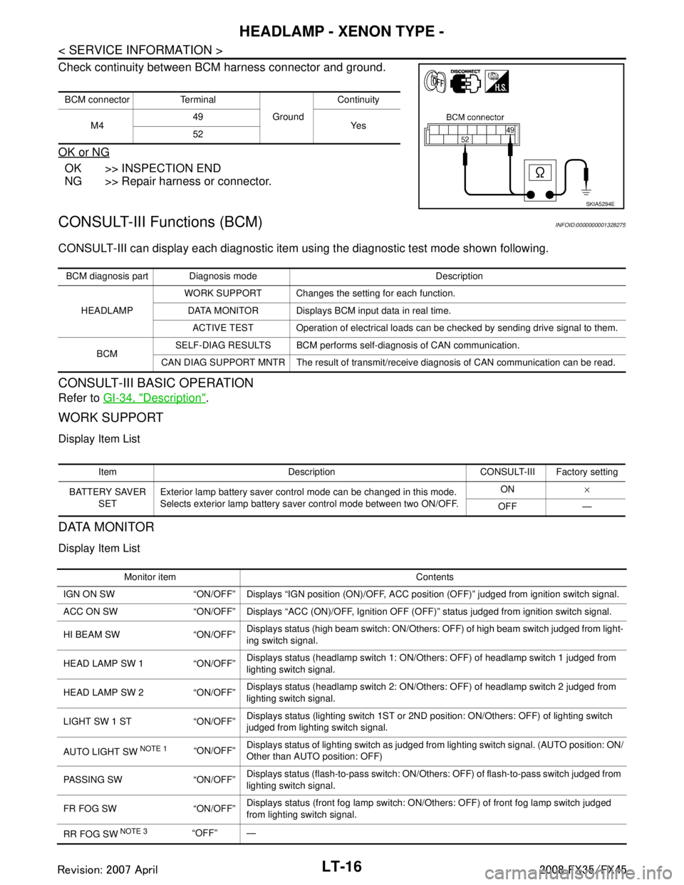
Check continuity between BCM harness connector and ground.
OK or NG
OK >> INSPECTION END
NG >> Repair harness or connector.
CONSULT-III Functions (BCM)INFOID:0000000001328275
CONSULT-III can display each diagnostic item using the diagnostic test mode shown following.
CONSULT-III BASIC OPERATION
Refer to GI-34, "Description".
WORK SUPPORT
Display Item List
DATA MONITOR
Display Item List
BCM connector Terminal
GroundContinuity
M4 49
Ye s
52
SKIA5294E
BCM diagnosis part Diagnosis mode Description
HEADLAMP WORK SUPPORT Changes the setting for each function.
DATA MONITOR Displays BCM input data in real time. ACTIVE TEST Operation of electrical loads can be checked by sending drive signal to them.
BCM SELF-DIAG RESULTS BCM performs self-diagnosis of CAN communication.
CAN DIAG SUPPORT MNTR The result of transmit/receive diagnosis of CAN communication can be read.
Item Description CONSULT-III Factory setting
BATTERY SAVER SET Exterior lamp battery saver control mode can be changed in this mode.
Selects exterior lamp battery saver control mode between two ON/OFF. ON
×
OFF —
Monitor item Contents
IGN ON SW “ON/OFF” Displays “IGN posi tion (ON)/OFF, ACC position (OFF)” judged from ignition switch signal.
ACC ON SW “ON/OFF” Displays “ACC (ON)/O FF, Ignition OFF (OFF)” status judged from ignition switch signal.
HI BEAM SW “ON/OFF” Displays status (high beam switch: ON/Others: OFF) of high beam switch judged from light-
ing switch signal.
HEAD LAMP SW 1 “ON/OFF” Displays status (headlamp switch 1: ON/Others: OFF) of headlamp switch 1 judged from
lighting switch signal.
HEAD LAMP SW 2 “ON/OFF” Displays status (headlamp switch 2: ON/Others: OFF) of headlamp switch 2 judged from
lighting switch signal.
LIGHT SW 1 ST “ON/OFF” Displays status (lighting switch 1ST or 2ND position: ON/Others: OFF) of lighting switch
judged from lighting switch signal.
AUTO LIGHT SW
NOTE 1 “ON/OFF” Displays status of lighting switch as judged from lighting switch signal. (AUTO position: ON/
Other than AUTO position: OFF)
PASSING SW “ON/OFF” Displays status (flash-to-pass switch: ON/Others: OFF) of flash-to-pass switch judged from
lighting switch signal.
FR FOG SW “ON/OFF” Displays status (front fog lamp switch: ON/Others: OFF) of front fog lamp switch judged
from lighting switch signal.
RR FOG SW
NOTE 3“OFF” —
3AA93ABC3ACD3AC03ACA3AC03AC63AC53A913A773A893A873A873A8E3A773A983AC73AC93AC03AC3
3A893A873A873A8F3A773A9D3AAF3A8A3A8C3A863A9D3AAF3A8B3A8C
Page 3119 of 3924
HEADLAMP - XENON TYPE -LT-17
< SERVICE INFORMATION >
C
DE
F
G H
I
J
L
M A
B
LT
N
O P
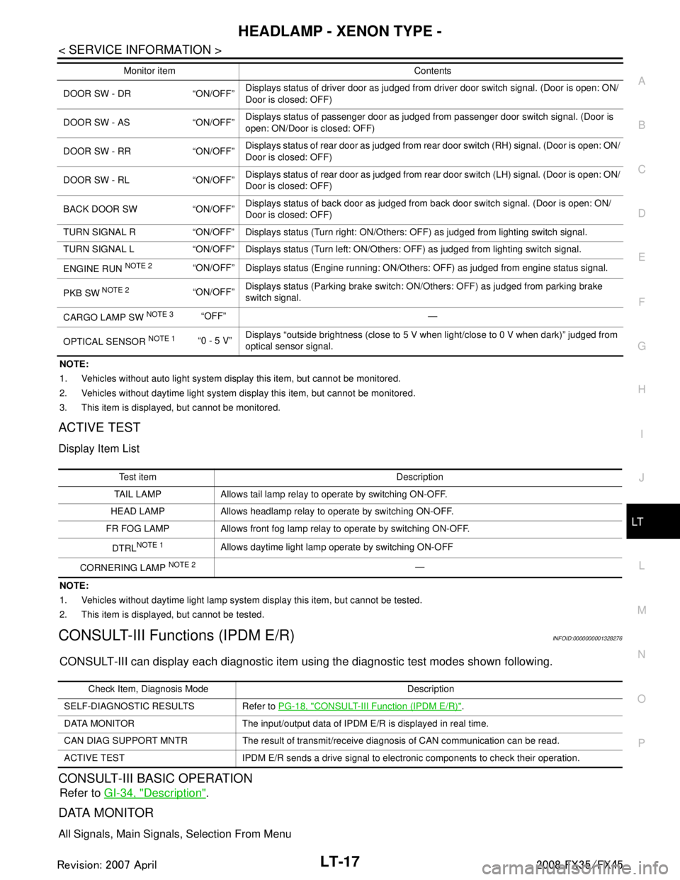
NOTE:
1. Vehicles without auto light system display this item, but cannot be monitored.
2. Vehicles without daytime light system display this item, but cannot be monitored.
3. This item is displayed, but cannot be monitored.
ACTIVE TEST
Display Item List
NOTE:
1. Vehicles without daytime light lamp system display this item, but cannot be tested.
2. This item is displayed, but cannot be tested.
CONSULT-III Functions (IPDM E/R)INFOID:0000000001328276
CONSULT-III can display each diagnostic item us ing the diagnostic test modes shown following.
CONSULT-III BASIC OPERATION
Refer to GI-34, "Description".
DATA MONITOR
All Signals, Main Signals, Selection From Menu
DOOR SW - DR “ON/OFF” Displays status of driver door as judged from driver door switch signal. (Door is open: ON/
Door is closed: OFF)
DOOR SW - AS “ON/OFF” Displays status of passenger door as judged from passenger door switch signal. (Door is
open: ON/Door is closed: OFF)
DOOR SW - RR “ON/OFF” Displays status of rear door as judged from rear door switch (RH) signal. (Door is open: ON/
Door is closed: OFF)
DOOR SW - RL “ON/OFF” Displays status of rear door as judged from rear door switch (LH) signal. (Door is open: ON/
Door is closed: OFF)
BACK DOOR SW “ON/OFF” Displays status of back door as judged from back door switch signal. (Door is open: ON/
Door is closed: OFF)
TURN SIGNAL R “ON/OFF” Display s status (Turn right: ON/Others: OFF) as judged from lighting switch signal.
TURN SIGNAL L “ON/OFF” Display s status (Turn left: ON/Others: OFF) as judged from lighting switch signal.
ENGINE RUN
NOTE 2“ON/OFF” Displays status (Engine running: ON/Others: OFF) as judged from engine status signal.
PKB SW
NOTE 2“ON/OFF” Displays status (Parking brake switch: ON/Others: OFF) as judged from parking brake
switch signal.
CARGO LAMP SW
NOTE 3 “OFF” —
OPTICAL SENSOR
NOTE 1 “0 - 5 V” Displays “outside brightness (close to 5 V when light/close to 0 V when dark)” judged from
optical sensor signal.
Monitor item Contents
Te s t i t e m D e s c r i p t i o n
TAIL LAMP Allows tail lamp relay to operate by switching ON-OFF.
HEAD LAMP Allows headlamp relay to operate by switching ON-OFF.
FR FOG LAMP Allows front fog lamp relay to operate by switching ON-OFF.
DTRL
NOTE 1Allows daytime light lamp operate by switching ON-OFF
CORNERING LAMP
NOTE 2—
Check Item, Diagnosis Mode Description
SELF-DIAGNOSTIC RESULTS Refer to PG-18, "
CONSULT-III Function (IPDM E/R)".
DATA MONITOR The input/output data of IPDM E/R is displayed in real time.
CAN DIAG SUPPORT MNTR The result of transmit/receive diagnosis of CAN communication can be read.
ACTIVE TEST IPDM E/R sends a drive signal to electronic components to check their operation.
3AA93ABC3ACD3AC03ACA3AC03AC63AC53A913A773A893A873A873A8E3A773A983AC73AC93AC03AC3
3A893A873A873A8F3A773A9D3AAF3A8A3A8C3A863A9D3AAF3A8B3A8C
Page 3120 of 3924
LT-18
< SERVICE INFORMATION >
HEADLAMP - XENON TYPE -
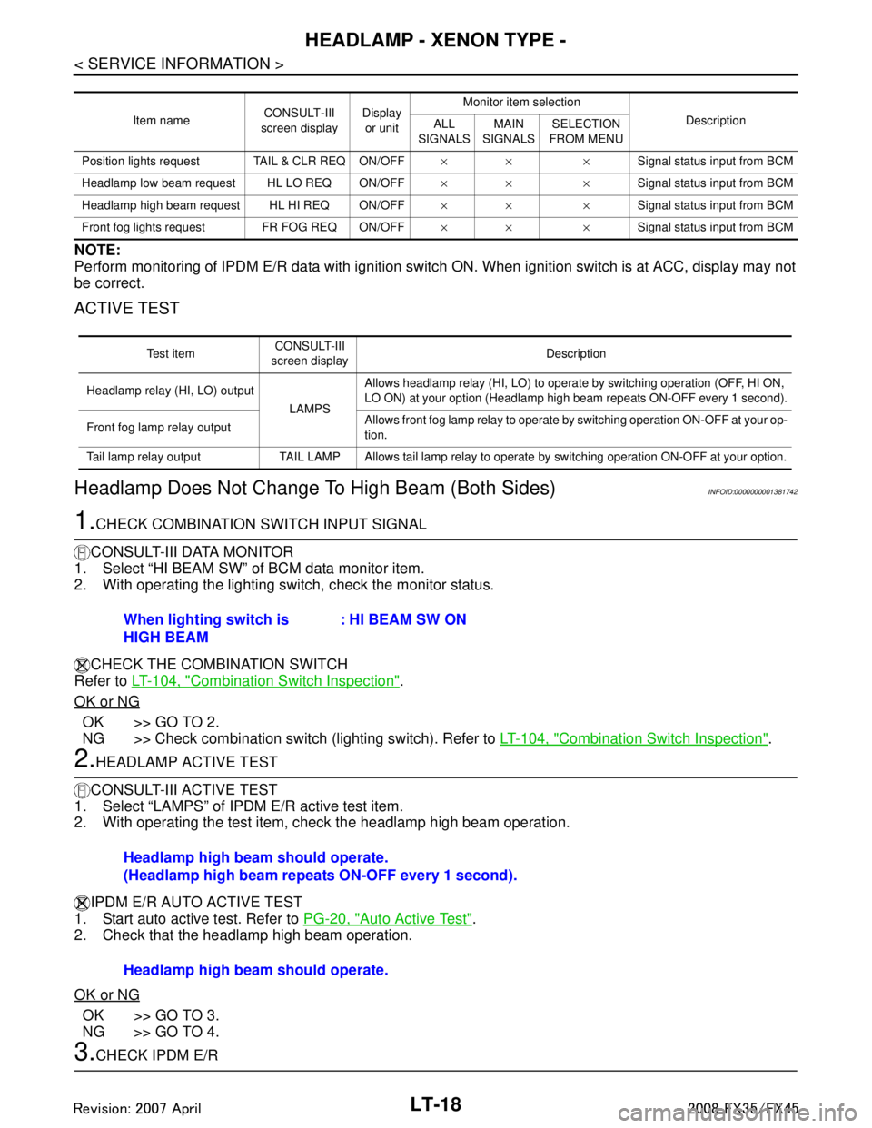
NOTE:
Perform monitoring of IPDM E/R data with ignition switch ON. When ignition switch is at ACC, display may not
be correct.
ACTIVE TEST
Headlamp Does Not Change To High Beam (Both Sides)INFOID:0000000001381742
1.CHECK COMBINATION SWITCH INPUT SIGNAL
CONSULT-III DATA MONITOR
1. Select “HI BEAM SW” of BCM data monitor item.
2. With operating the lighting switch, check the monitor status.
CHECK THE COMBINATION SWITCH
Refer to LT-104, "
Combination Switch Inspection".
OK or NG
OK >> GO TO 2.
NG >> Check combination switch (lighting switch). Refer to LT-104, "
Combination Switch Inspection".
2.HEADLAMP ACTIVE TEST
CONSULT-III ACTIVE TEST
1. Select “LAMPS” of IPDM E/R active test item.
2. With operating the test item, check the headlamp high beam operation.
IPDM E/R AUTO ACTIVE TEST
1. Start auto active test. Refer to PG-20, "
Auto Active Test".
2. Check that the headlamp high beam operation.
OK or NG
OK >> GO TO 3.
NG >> GO TO 4.
3.CHECK IPDM E/R
Item name CONSULT-III
screen display Display
or unit Monitor item selection
Description
ALL
SIGNALS MAIN
SIGNALS SELECTION
FROM MENU
Position lights request TAIL & CLR REQ ON/OFF ×× ×Signal status input from BCM
Headlamp low beam request HL LO REQ ON/OFF ×× ×Signal status input from BCM
Headlamp high beam request HL HI REQ ON/OFF ×× ×Signal status input from BCM
Front fog lights request FR FOG REQ ON/OFF ×× ×Signal status input from BCM
Te s t i t e mCONSULT-III
screen display Description
Headlamp relay (HI, LO) output
LAMPSAllows headlamp relay (HI, LO) to operate by switching operation (OFF, HI ON,
LO ON) at your option (Headlamp high beam repeats ON-OFF every 1 second).
Front fog lamp relay output Allows front fog lamp relay to operate by switching operation ON-OFF at your op-
tion.
Tail lamp relay output TAIL LAMP Allows tail lamp relay to operate by switching operation ON-OFF at your option.
When lighting switch is
HIGH BEAM : HI BEAM SW ON
Headlamp high beam should operate.
(Headlamp high beam repeats ON-OFF every 1 second).
Headlamp high beam should operate.
3AA93ABC3ACD3AC03ACA3AC03AC63AC53A913A773A893A873A873A8E3A773A983AC73AC93AC03AC3
3A893A873A873A8F3A773A9D3AAF3A8A3A8C3A863A9D3AAF3A8B3A8C
Page 3141 of 3924
DAYTIME LIGHT SYSTEMLT-39
< SERVICE INFORMATION >
C
DE
F
G H
I
J
L
M A
B
LT
N
O P
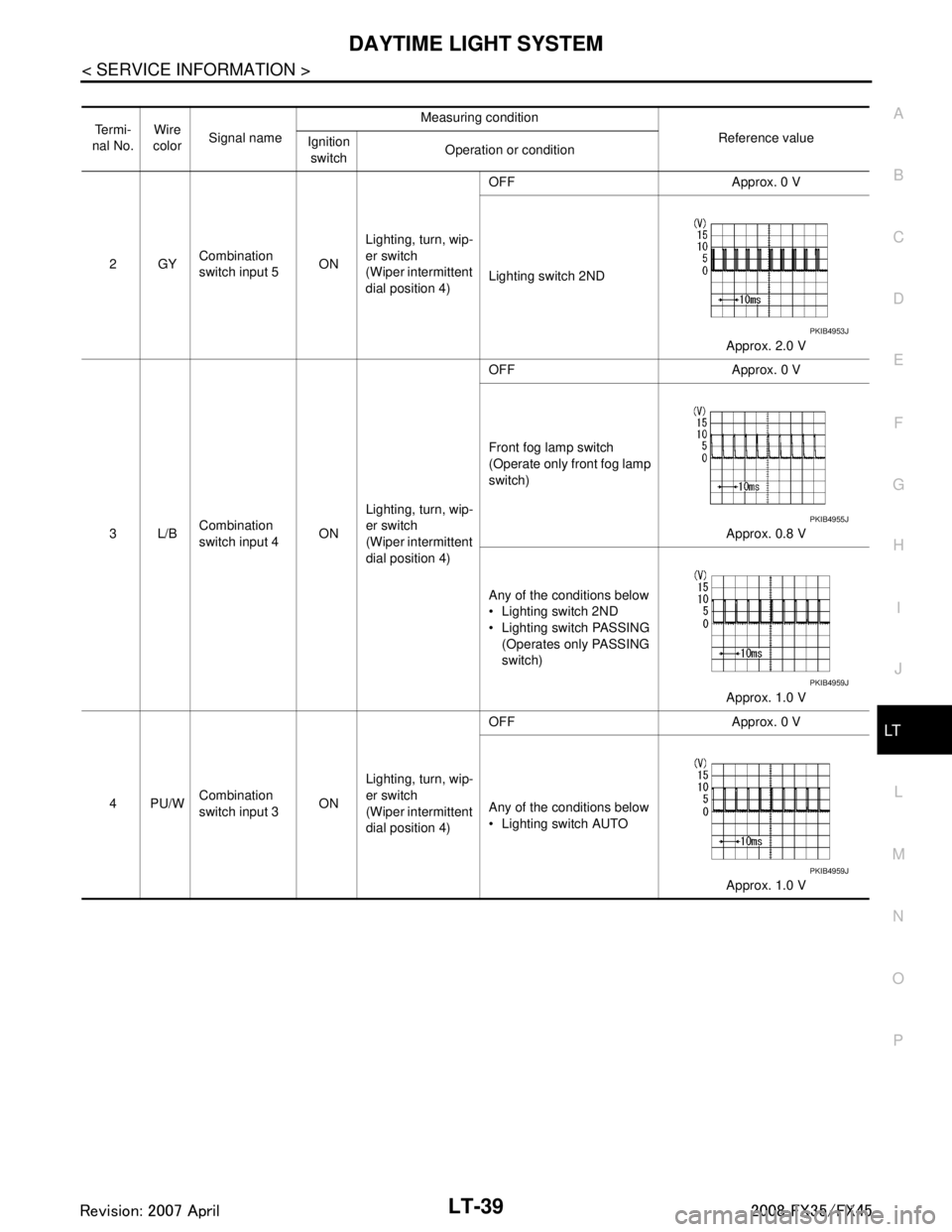
Te r m i -
nal No. Wire
color Signal name Measuring condition
Reference value
Ignition
switch Operation or condition
2GY Combination
switch input 5
ONLighting, turn, wip-
er switch
(Wiper intermittent
dial position 4) OFF Approx. 0 V
Lighting switch 2ND
Approx. 2.0 V
3L/B Combination
switch input 4
ONLighting, turn, wip-
er switch
(Wiper intermittent
dial position 4) OFF Approx. 0 V
Front fog lamp switch
(Operate only front fog lamp
switch)
Approx. 0.8 V
Any of the conditions below
Lighting switch 2ND
Lighting switch PASSING (Operates only PASSING
switch)
Approx. 1.0 V
4PU/W Combination
switch input 3 ONLighting, turn, wip-
er switch
(Wiper intermittent
dial position 4) OFF Approx. 0 V
Any of the conditions below
Lighting switch AUTO
Approx. 1.0 V
PKIB4953J
PKIB4955J
PKIB4959J
PKIB4959J
3AA93ABC3ACD3AC03ACA3AC03AC63AC53A913A773A893A873A873A8E3A773A983AC73AC93AC03AC3
3A893A873A873A8F3A773A9D3AAF3A8A3A8C3A863A9D3AAF3A8B3A8C
Page 3142 of 3924

LT-40
< SERVICE INFORMATION >
DAYTIME LIGHT SYSTEM
32 GY/RCombination
switch output 5 ONLighting, turn, wip-
er switch (Wiper
intermittent dial
position 4) OFF
Approx. 7.2 V
Front fog lamp switch
(Operates only front fog
lamp switch) Approx. 1.0 V
33 G Combination
switch output 4
ONLighting, turn, wip-
er switch (Wiper
intermittent dial
position 4) OFF
Approx. 7.2 V
Lighting switch AUTO Approx. 1.2 V
34 W/B Combination
switch output 3 ONLighting, turn, wip-
er switch (Wiper
intermittent dial
position 4) OFF
Approx. 7.2 V
Lighting switch 2ND Approx. 1.2 V
Te r m i -
nal No. Wire
color Signal name Measuring condition
Reference value
Ignition
switch Operation or condition
PKIB4960J
PKIB4956J
PKIB4960J
PKIB4958J
PKIB4960J
PKIB4958J
3AA93ABC3ACD3AC03ACA3AC03AC63AC53A913A773A893A873A873A8E3A773A983AC73AC93AC03AC3
3A893A873A873A8F3A773A9D3AAF3A8A3A8C3A863A9D3AAF3A8B3A8C
Page 3145 of 3924
DAYTIME LIGHT SYSTEMLT-43
< SERVICE INFORMATION >
C
DE
F
G H
I
J
L
M A
B
LT
N
O P
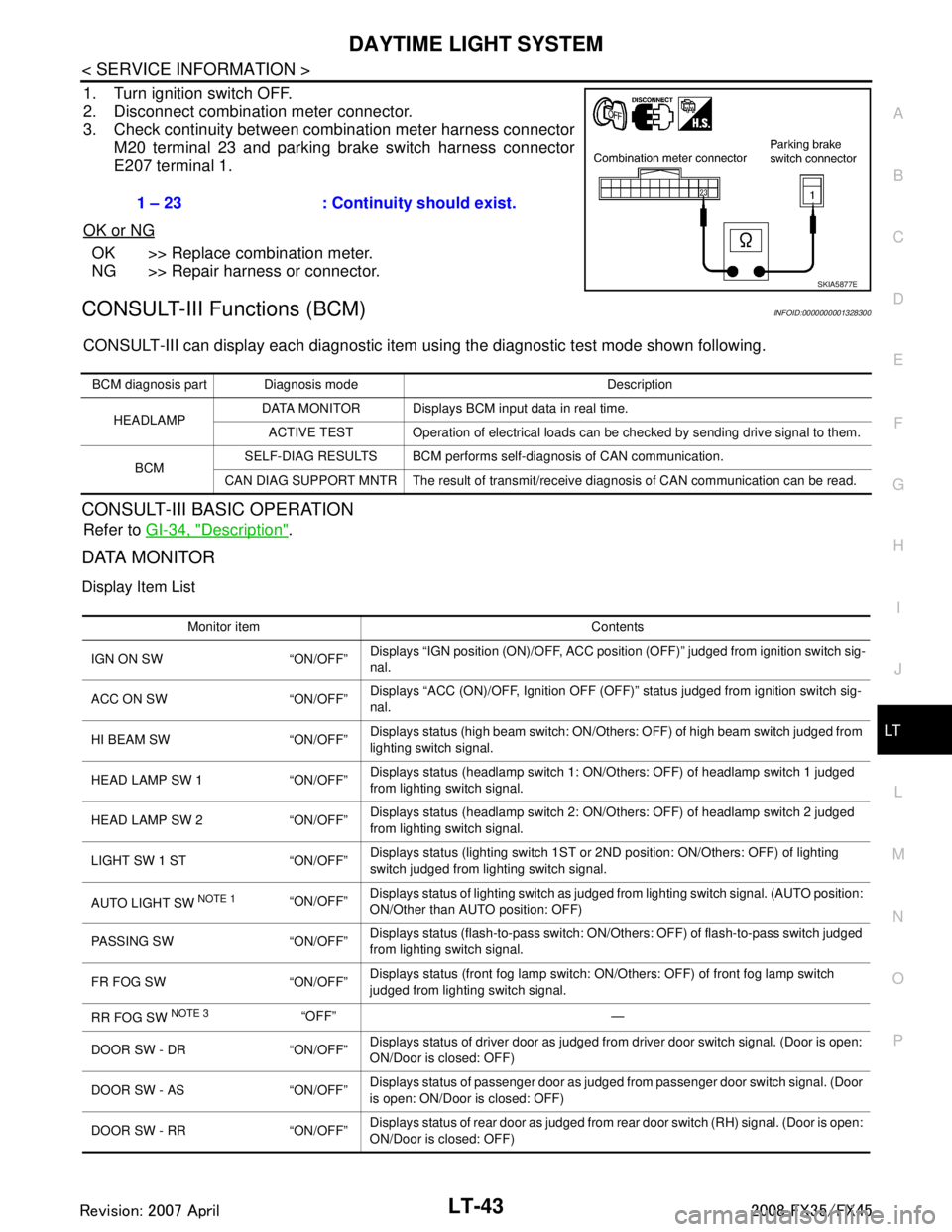
1. Turn ignition switch OFF.
2. Disconnect combination meter connector.
3. Check continuity between combination meter harness connector M20 terminal 23 and parking brake switch harness connector
E207 terminal 1.
OK or NG
OK >> Replace combination meter.
NG >> Repair harness or connector.
CONSULT-III Functions (BCM)INFOID:0000000001328300
CONSULT-III can display each diagnostic item using the diagnostic test mode shown following.
CONSULT-III BASIC OPERATION
Refer to GI-34, "Description".
DATA MONITOR
Display Item List
1 – 23 : Continuity should exist.
SKIA5877E
BCM diagnosis part Diagnosis mode Description
HEADLAMP DATA MONITOR Displays BCM input data in real time.
ACTIVE TEST Operation of electrical loads can be checked by sending drive signal to them.
BCM SELF-DIAG RESULTS BCM performs self-diagnosis of CAN communication.
CAN DIAG SUPPORT MNTR The result of transmit/receive diagnosis of CAN communication can be read.
Monitor item Contents
IGN ON SW “ON/OFF” Displays “IGN position (ON)/OFF, ACC position (OFF)” judged from ignition switch sig-
nal.
ACC ON SW “ON/OFF” Displays “ACC (ON)/OFF, Ignition OFF (OFF)”
status judged from ignition switch sig-
nal.
HI BEAM SW “ON/OFF” Displays status (high beam switch: ON/Others: OFF) of high beam switch judged from
lighting switch signal.
HEAD LAMP SW 1 “ON/OFF” Displays status (headlamp switch 1: ON/Others: OFF) of headlamp switch 1 judged
from lighting switch signal.
HEAD LAMP SW 2 “ON/OFF” Displays status (headlamp switch 2: ON/Others: OFF) of headlamp switch 2 judged
from lighting switch signal.
LIGHT SW 1 ST “ON/OFF” Displays status (lighting switch 1ST or 2ND position: ON/Others: OFF) of lighting
switch judged from lighting switch signal.
AUTO LIGHT SW
NOTE 1 “ON/OFF” Displays status of lighting switch as judged from lighting switch signal. (AUTO position:
ON/Other than AUTO position: OFF)
PASSING SW “ON/OFF” Displays status (flash-to-pass switch: ON/Others: OFF) of flash-to-pass switch judged
from lighting switch signal.
FR FOG SW “ON/OFF” Displays status (front fog lamp switch: ON/Others: OFF) of front fog lamp switch
judged from lighting switch signal.
RR FOG SW
NOTE 3“OFF” —
DOOR SW - DR “ON/OFF” Displays status of driver door as judged from driver door switch signal. (Door is open:
ON/Door is closed: OFF)
DOOR SW - AS “ON/OFF” Displays status of passenger door as judged from passenger door switch signal. (Door
is open: ON/Door is closed: OFF)
DOOR SW - RR “ON/OFF” Displays status of rear door as judged from rear door switch (RH) signal. (Door is open:
ON/Door is closed: OFF)
3AA93ABC3ACD3AC03ACA3AC03AC63AC53A913A773A893A873A873A8E3A773A983AC73AC93AC03AC3
3A893A873A873A8F3A773A9D3AAF3A8A3A8C3A863A9D3AAF3A8B3A8C
Page 3146 of 3924
LT-44
< SERVICE INFORMATION >
DAYTIME LIGHT SYSTEM
NOTE:
1. Vehicles without auto light system display this item, but cannot be monitored.
2. Vehicles without daytime light system display this item, but cannot be monitored.
3. This item is displayed, but cannot be monitored.
ACTIVE TEST
Display Item List
NOTE:
1. Vehicles without daytime light lamp system display this item, but cannot be tested.
2. This item is displayed, but cannot be tested.
Daytime Light Control Does Not Operate ProperlyINFOID:0000000001328301
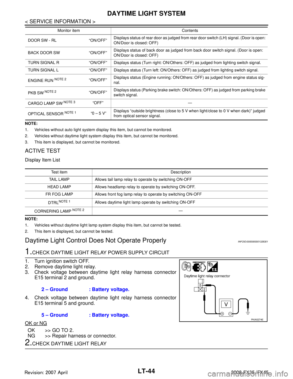
1.CHECK DAYTIME LIGHT RELAY POWER SUPPLY CIRCUIT
1. Turn ignition switch OFF.
2. Remove daytime light relay.
3. Check voltage between daytime light relay harness connector E15 terminal 2 and ground.
4. Check voltage between daytime light relay harness connector E15 terminal 5 and ground.
OK or NG
OK >> GO TO 2.
NG >> Repair harness or connector.
2.CHECK DAYTIME LIGHT RELAY
DOOR SW - RL “ON/OFF” Displays status of rear door as judged from rear door switch (LH) signal. (Door is open:
ON/Door is closed: OFF)
BACK DOOR SW “ON/OFF” Displays status of back door as judged from back door switch signal. (Door is open:
ON/Door is closed: OFF)
TURN SIGNAL R “ON/OFF” Displays status (Turn right: ON/Others: OFF) as judged from lighting switch signal.
TURN SIGNAL L “ON/OFF” Displays status (Turn left: ON/Others: OFF) as judged from lighting switch signal.
ENGINE RUN
NOTE 2“ON/OFF” Displays status (Engine running: ON/Others: OFF) as judged from engine status sig-
nal.
PKB SW
NOTE 2“ON/OFF” Displays status (Parking brake switch: ON/Others: OFF) as judged from parking brake
switch signal.
CARGO LAMP SW
NOTE 3 “OFF” —
OPTICAL SENSOR
NOTE 1 “0 – 5 V” Displays “outside brightness (close to 5 V when light/close to 0 V when dark)” judged
from optical sensor signal.
Monitor item Contents
Test item Description
TAIL LAMP Allows tail lamp relay to operate by switching ON-OFF
HEAD LAMP Allows headlamp relay to operate by switching ON-OFF.
FR FOG LAMP Allows front fog lamp relay to operate by switching ON-OFF
DTRL
NOTE 1Allows daytime light lamp operate by switching ON-OFF
CORNERING LAMP
NOTE 2—
2 – Ground : Battery voltage.
5 – Ground : Battery voltage.
PKIA5274E
3AA93ABC3ACD3AC03ACA3AC03AC63AC53A913A773A893A873A873A8E3A773A983AC73AC93AC03AC3
3A893A873A873A8F3A773A9D3AAF3A8A3A8C3A863A9D3AAF3A8B3A8C