Page 2474 of 3924
DOOR FINISHEREI-37
< SERVICE INFORMATION >
C
DE
F
G H
J
K L
M A
B
EI
N
O P
3. Insert screw driver rolled with cloth between panel on vehicle and clips (as indicated with arrow), and remove finisher.
4. Pull up door finisher, and remove electrical parts connectors.
5. Remove lock knob cable, inside handle cable and illumination harness connector (front door only) from backside of inside han-
dle assembly.
6. Remove the following parts after removing door finisher. Inside handle
Seat memory switch and seat memory switch finisher
Power window switch
Step lamp
Installation
Install in the reverse order of removal.
CAUTION:
To install finisher, check if all clips are matched over holes of panel on vehicle, then push it.
SIIA0810E
PIIA4959E
3AA93ABC3ACD3AC03ACA3AC03AC63AC53A913A773A893A873A873A8E3A773A983AC73AC93AC03AC3
3A893A873A873A8F3A773A9D3AAF3A8A3A8C3A863A9D3AAF3A8B3A8C
Page 2475 of 3924
EI-38
< SERVICE INFORMATION >
BODY SIDE TRIM
BODY SIDE TRIM
Component Parts LocationINFOID:0000000001328075
Removal and InstallationINFOID:0000000001529410
CAUTION:
Wrap the tip of flat-bladed screwdriver with a cloth when removing metal clips from garnishes.
CENTER PILLAR LOWER GARNISH
Removal
1. Remove front and rear kicking plate.
2. Remove front and rear body side welt.
1. Front pillar garnish 2. Front body side welt 3. Dash side finisher
4. Nut 5. Front kicking plate 6. Center pillar lower garnish
7. Center pillar upper garnish 8. Bolt 9. Center pillar upper cap
10. Rear body side welt 11. Rear kicking plate 12. Clip (C203)
13. Center mudguard finisher (rear) 14. Center mudguard finisher (front)
PIIA4340E
PIIA4344E
3AA93ABC3ACD3AC03ACA3AC03AC63AC53A913A773A893A873A873A8E3A773A983AC73AC93AC03AC3
3A893A873A873A8F3A773A9D3AAF3A8A3A8C3A863A9D3AAF3A8B3A8C
Page 2476 of 3924

BODY SIDE TRIMEI-39
< SERVICE INFORMATION >
C
DE
F
G H
J
K L
M A
B
EI
N
O P
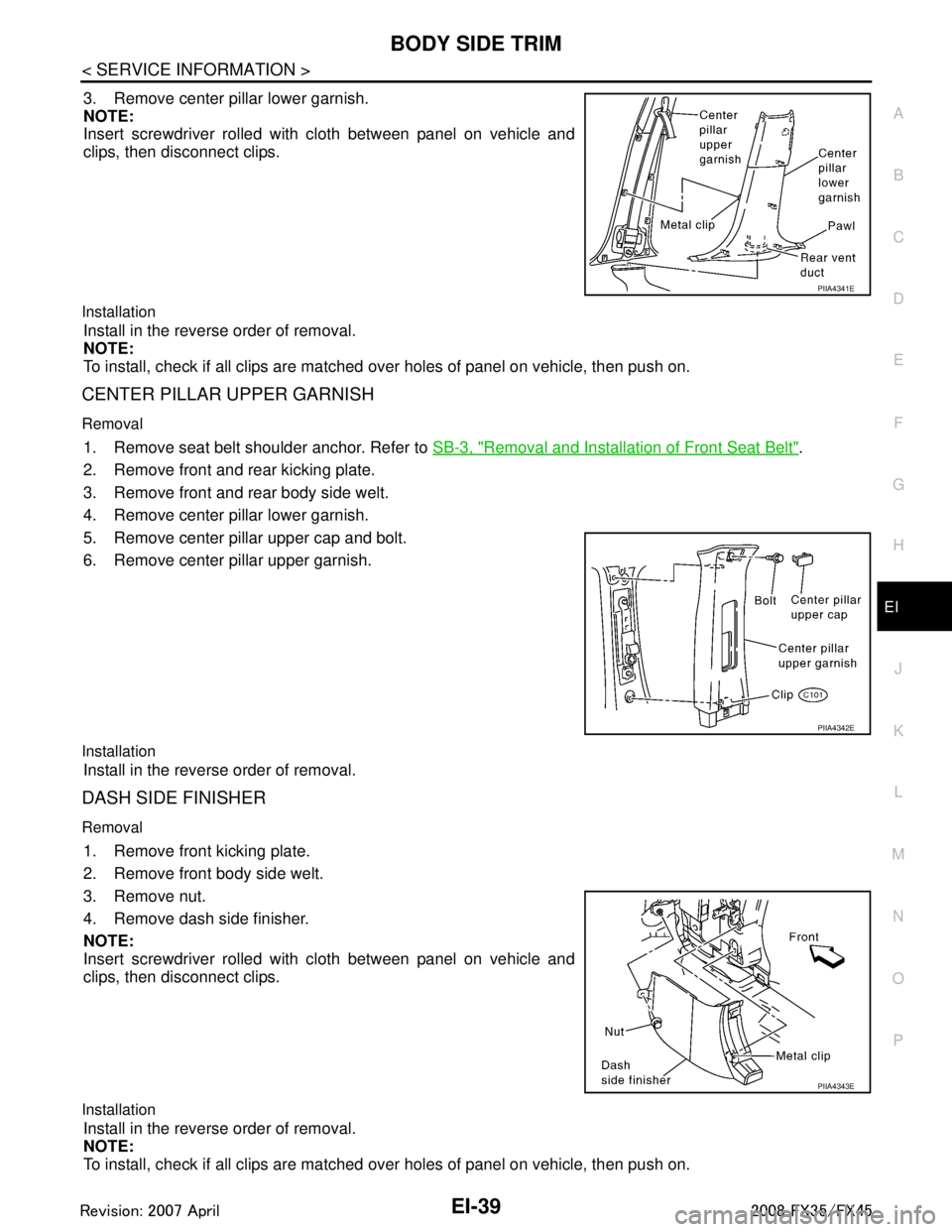
3. Remove center pillar lower garnish.
NOTE:
Insert screwdriver rolled with cloth between panel on vehicle and
clips, then disconnect clips.
Installation
Install in the reverse order of removal.
NOTE:
To install, check if all clips are matched over holes of panel on vehicle, then push on.
CENTER PILLAR UPPER GARNISH
Removal
1. Remove seat belt shoulder anchor. Refer to SB-3, "Removal and Installation of Front Seat Belt".
2. Remove front and rear kicking plate.
3. Remove front and rear body side welt.
4. Remove center pillar lower garnish.
5. Remove center pillar upper cap and bolt.
6. Remove center pillar upper garnish.
Installation
Install in the reverse order of removal.
DASH SIDE FINISHER
Removal
1. Remove front kicking plate.
2. Remove front body side welt.
3. Remove nut.
4. Remove dash side finisher.
NOTE:
Insert screwdriver rolled with cloth between panel on vehicle and
clips, then disconnect clips.
Installation
Install in the reverse order of removal.
NOTE:
To install, check if all clips are matched over holes of panel on vehicle, then push on.
PIIA4341E
PIIA4342E
PIIA4343E
3AA93ABC3ACD3AC03ACA3AC03AC63AC53A913A773A893A873A873A8E3A773A983AC73AC93AC03AC3
3A893A873A873A8F3A773A9D3AAF3A8A3A8C3A863A9D3AAF3A8B3A8C
Page 2477 of 3924
EI-40
< SERVICE INFORMATION >
BODY SIDE TRIM
FRONT PILLAR GARNISH
Removal
Remove front pillar garnish clips and remove front pillar garnish.
Installation
Install in the reverse order of removal.
KICKING PLATE
Removal
Remove kicking plate clips and remove kicking plate.
Installation
Install in the reverse order of removal.
CENTER MUDGUARD FINISHER (FRONT/REAR)
Removal
1. Remove center mudguard finisher (front).
2. Remove center mudguard finisher clip and remove center mud-guard finisher (rear).
Installation
Install in the reverse order of removal.
PIIA4345E
PIIA4346E
3AA93ABC3ACD3AC03ACA3AC03AC63AC53A913A773A893A873A873A8E3A773A983AC73AC93AC03AC3
3A893A873A873A8F3A773A9D3AAF3A8A3A8C3A863A9D3AAF3A8B3A8C
Page 2478 of 3924

FLOOR TRIMEI-41
< SERVICE INFORMATION >
C
DE
F
G H
J
K L
M A
B
EI
N
O P
FLOOR TRIM
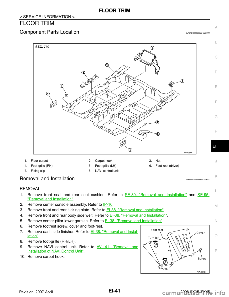
Component Parts LocationINFOID:0000000001328076
Removal and InstallationINFOID:0000000001529411
REMOVAL
1. Remove front seat and rear seat cushion. Refer to SE-89, "Removal and Installation" and SE-95,
"Removal and Installation".
2. Remove center console assembly. Refer to IP-10
.
3. Remove front and rear kicking plate. Refer to EI-38, "
Removal and Installation".
4. Remove front and rear body side welt. Refer to EI-38, "
Removal and Installation".
5. Remove center pillar lower garnish. Refer to EI-38, "
Removal and Installation".
6. Remove footrest screw, cover and foot-rest.
7. Remove dash side finisher. Refer to EI-38, "
Removal and Instal-
lation".
8. Remove foot-grille (RH/LH).
9. Remove NAVI control unit. Refer to AV-141, "
Removal and
Installation of NAVI Control Unit".
10. Remove carpet hook.
1. Floor carpet 2. Carpet hook 3. Nut
4. Foot-grille (RH) 5. Foot-gri lle (LH) 6. Foot-rest (driver)
7. Fixing clip 8. NAVI control unit
PIIA4956E
PIIA4957E
3AA93ABC3ACD3AC03ACA3AC03AC63AC53A913A773A893A873A873A8E3A773A983AC73AC93AC03AC3
3A893A873A873A8F3A773A9D3AAF3A8A3A8C3A863A9D3AAF3A8B3A8C
Page 2479 of 3924
EI-42
< SERVICE INFORMATION >
FLOOR TRIM
11. Remove floor carpet from carpet fixing clip and remove floor car-pet.
INSTALLATION
Install in the reverse order of removal.
PIIA1223E
3AA93ABC3ACD3AC03ACA3AC03AC63AC53A913A773A893A873A873A8E3A773A983AC73AC93AC03AC3
3A893A873A873A8F3A773A9D3AAF3A8A3A8C3A863A9D3AAF3A8B3A8C
Page 2480 of 3924
HEADLININGEI-43
< SERVICE INFORMATION >
C
DE
F
G H
J
K L
M A
B
EI
N
O P
HEADLINING
Component Parts LocationINFOID:0000000001328077
1. Headlining 2. Assist grip (rear) 3. Assist grip (front)
4. Sun-visor holder (RH) 5. Sun-vi sor (RH) 6. Sun-visor cover (RH)
PIIB3263E
3AA93ABC3ACD3AC03ACA3AC03AC63AC53A913A773A893A873A873A8E3A773A983AC73AC93AC03AC3
3A893A873A873A8F3A773A9D3AAF3A8A3A8C3A863A9D3AAF3A8B3A8C
Page 2481 of 3924

EI-44
< SERVICE INFORMATION >
HEADLINING
Removal and Installation
INFOID:0000000001529412
REMOVAL
1. Remove front pillar garnish. Refer to EI-38, "Removal and Installation".
2. Remove kicking plate (front/rear). Refer to EI-38, "
Removal and Installation".
3. Remove body side welt. Refer to EI-38, "
Removal and Installation".
4. Remove seat belt shoulder anchor (front/rear). Refer to SB-3, "
Removal and Installation of Front Seat
Belt" and SB-5, "Removal and Installation of Rear Seat Belt".
5. Remove center pillar garnish (lower/upper) and luggage side finisher assembly and rear pillar upper gar- nish assembly. Refer to EI-38, "
Removal and Installation" and EI-46, "Removal and Installation".
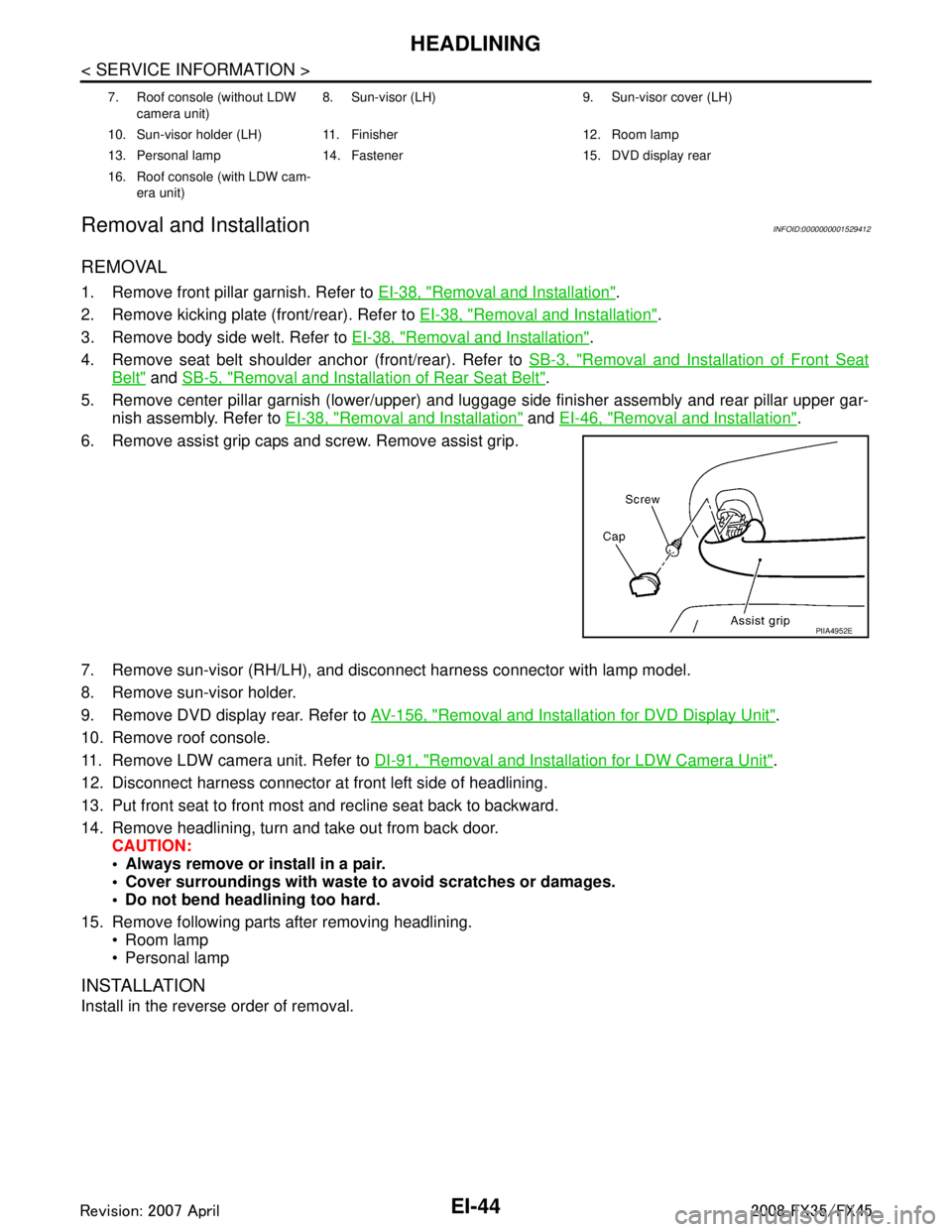
6. Remove assist grip caps and screw. Remove assist grip.
7. Remove sun-visor (RH/LH), and disconnect harness connector with lamp model.
8. Remove sun-visor holder.
9. Remove DVD display rear. Refer to AV-156, "
Removal and Installation for DVD Display Unit".
10. Remove roof console.
11. Remove LDW camera unit. Refer to DI-91, "
Removal and Installation for LDW Camera Unit".
12. Disconnect harness connector at front left side of headlining.
13. Put front seat to front most and recline seat back to backward.
14. Remove headlining, turn and take out from back door. CAUTION:
Always remove or install in a pair.
Cover surroundings with waste to avoid scratches or damages.
Do not bend headlining too hard.
15. Remove following parts after removing headlining. Room lamp
Personal lamp
INSTALLATION
Install in the reverse order of removal.
7. Roof console (without LDW
camera unit) 8. Sun-visor (LH) 9. Sun-visor cover (LH)
10. Sun-visor holder (LH) 11. Finisher 12. Room lamp
13. Personal lamp 14. Fastener 15. DVD display rear
16. Roof console (with LDW cam- era unit)
PIIA4952E
3AA93ABC3ACD3AC03ACA3AC03AC63AC53A913A773A893A873A873A8E3A773A983AC73AC93AC03AC3
3A893A873A873A8F3A773A9D3AAF3A8A3A8C3A863A9D3AAF3A8B3A8C