2008 INFINITI FX35 dimensions
[x] Cancel search: dimensionsPage 2718 of 3924
![INFINITI FX35 2008 Service Manual
EM-234
< SERVICE INFORMATION >[VK45DE]
CYLINDER HEAD
3. Using valve guide reamer (commercial service tool), ream cylin-
der head valve guide hole.
4. Heat cylinder head to 110 to 130 °C (230 to 266 INFINITI FX35 2008 Service Manual
EM-234
< SERVICE INFORMATION >[VK45DE]
CYLINDER HEAD
3. Using valve guide reamer (commercial service tool), ream cylin-
der head valve guide hole.
4. Heat cylinder head to 110 to 130 °C (230 to 266](/manual-img/42/57017/w960_57017-2717.png)
EM-234
< SERVICE INFORMATION >[VK45DE]
CYLINDER HEAD
3. Using valve guide reamer (commercial service tool), ream cylin-
der head valve guide hole.
4. Heat cylinder head to 110 to 130 °C (230 to 266 °F) by soaking in
heated oil.
5. Using valve guide drift (commercial service tool), press valve guide from camshaft side to the dimensions as in the figure.
CAUTION:
Cylinder head contains heat . When working, wear protec-
tive equipment to avo id getting burned.
6. Using valve guide reamer (commercial service tool), apply reamer finish to valve guide.
VALVE SEAT CONTACT
After confirming that the dimensi ons of valve guides and valves are
within the specifications, perform this procedure.
Apply prussian blue (or white lead) onto contacting surface of valve
seat to check the condition of the valve contact on the surface.
Check if the contact area band is continuous all around the circum- ference.
If not, grind to adjust valve fitting and check again. If the contacting surface still has “NG” conditions even after the re-check, replace
valve seat. Refer to "VALVE SEAT REPLACEMENT". Valve guide hole diameter (for service parts):
Intake and exhaust: 10.175 - 10.196 mm (0.4006 - 0.4014 in)
SEM932C
SEM008A
PBIC0078E
Standard: Intake and exhaust: 6.000 - 6.018 mm (0.2362 - 0.2369 in)
SEM932C
SBIA0322E
3AA93ABC3ACD3AC03ACA3AC03AC63AC53A913A773A893A873A873A8E3A773A983AC73AC93AC03AC3
3A893A873A873A8F3A773A9D3AAF3A8A3A8C3A863A9D3AAF3A8B3A8C
Page 2719 of 3924
![INFINITI FX35 2008 Service Manual
CYLINDER HEADEM-235
< SERVICE INFORMATION > [VK45DE]
C
D
E
F
G H
I
J
K L
M A
EM
NP
O
VALVE SEAT REPLACEMENT
When valve seat is removed, replace with
oversized [0.5 mm (0.020 in)] valve seat.
1. Bore INFINITI FX35 2008 Service Manual
CYLINDER HEADEM-235
< SERVICE INFORMATION > [VK45DE]
C
D
E
F
G H
I
J
K L
M A
EM
NP
O
VALVE SEAT REPLACEMENT
When valve seat is removed, replace with
oversized [0.5 mm (0.020 in)] valve seat.
1. Bore](/manual-img/42/57017/w960_57017-2718.png)
CYLINDER HEADEM-235
< SERVICE INFORMATION > [VK45DE]
C
D
E
F
G H
I
J
K L
M A
EM
NP
O
VALVE SEAT REPLACEMENT
When valve seat is removed, replace with
oversized [0.5 mm (0.020 in)] valve seat.
1. Bore out old seat until it collapses. Boring shoul d not continue beyond the bottom face of the seat recess
in cylinder head. Set the machine depth stop to ensure this. Refer to EM-266, "
Standard and Limit".
CAUTION:
Prevent to scratch cylinder head by excessive boring.
2. Ream cylinder head recess diameter for service valve seat.
Be sure to ream in circles concentric to valve guide center.This will enable valve to fit correctly.
3. Heat cylinder head to 110 to 130 °C (230 to 266 °F) by soaking in
heated oil.
4. Provide valve seats cooled well with dry ice. Force fit valve seat into cylinder head. CAUTION:
Avoid directly touching cold valve seats.
Cylinder head contains heat. Wh en working, wear protective equipment to avoid getting burned.
5. Using valve seat cutter set (commercial service tool) or valve seat grinder, finish seat to the specified dimensions. Refer to
EM-266, "
Standard and Limit".
CAUTION:
When using valve seat cutter, firmly grip cutter handle with
both hands. Then, press on the contacting surface all
around the circumference to cu t in a single drive. Improper
pressure on with cutter or cu tting many different times may
result in stage valve seat.
6. Using compound, grind to adjust valve fitting.
7. Check again for normal contact. Refer to "VALVE SEAT CONTACT".
VALVE SPRING SQUARENESS
Oversize (Service) [0.5 mm (0.020 in)] Intake : 37.500 - 37.516 mm (1.4764 - 1.4770 in)
Exhaust : 32.700 - 32.716 mm (1.2874 - 1.2880 in)
SEM795A
SEM008A
SEM934C
3AA93ABC3ACD3AC03ACA3AC03AC63AC53A913A773A893A873A873A8E3A773A983AC73AC93AC03AC3
3A893A873A873A8F3A773A9D3AAF3A8A3A8C3A863A9D3AAF3A8B3A8C
Page 2720 of 3924
![INFINITI FX35 2008 Service Manual
EM-236
< SERVICE INFORMATION >[VK45DE]
CYLINDER HEAD
Set try square along the side of valve spring and rotate spring.
Measure the maximum clearance between the top face of spring
and try square.
INFINITI FX35 2008 Service Manual
EM-236
< SERVICE INFORMATION >[VK45DE]
CYLINDER HEAD
Set try square along the side of valve spring and rotate spring.
Measure the maximum clearance between the top face of spring
and try square.
](/manual-img/42/57017/w960_57017-2719.png)
EM-236
< SERVICE INFORMATION >[VK45DE]
CYLINDER HEAD
Set try square along the side of valve spring and rotate spring.
Measure the maximum clearance between the top face of spring
and try square.
If it exceeds the limit, replace valve spring.
VALVE SPRING DIMENSIONS AND VALVE SPRING PRESSURE LOAD
Check valve spring pressure at the specified spring height.
If the installation load or load with valve open is out of the standard, replace valve spring.
Limit : 2.0 mm (0.079 in)
PBIC0080E
Standard:
Intake and exhaustFree height : 46.35 - 46.85 mm (1.8248 - 1.8445 in)
Installation height : 33.8 mm (1.331 in)
Installation load : 165 - 189 N (16.8 - 19.3 kg, 37 - 42 lb)
Height during valve open : 24.4 mm (0.961 in)
Load with valve open : 290 - 330 N (29.6 - 33.7 kg, 65 - 74 lb)
SEM113
3AA93ABC3ACD3AC03ACA3AC03AC63AC53A913A773A893A873A873A8E3A773A983AC73AC93AC03AC3
3A893A873A873A8F3A773A9D3AAF3A8A3A8C3A863A9D3AAF3A8B3A8C
Page 2746 of 3924
![INFINITI FX35 2008 Service Manual
EM-262
< SERVICE INFORMATION >[VK45DE]
CYLINDER BLOCK
Re-boring Cylinder Bore
1. Cylinder bore size is determined by adding piston to
cylinder bore clearance to piston skirt diameter.
2. Install mai INFINITI FX35 2008 Service Manual
EM-262
< SERVICE INFORMATION >[VK45DE]
CYLINDER BLOCK
Re-boring Cylinder Bore
1. Cylinder bore size is determined by adding piston to
cylinder bore clearance to piston skirt diameter.
2. Install mai](/manual-img/42/57017/w960_57017-2745.png)
EM-262
< SERVICE INFORMATION >[VK45DE]
CYLINDER BLOCK
Re-boring Cylinder Bore
1. Cylinder bore size is determined by adding piston to
cylinder bore clearance to piston skirt diameter.
2. Install main bearing caps and main bearing, and tight en to the specified torque. Otherwise, cylinder bores
may be distorted in final assembly.
3. Cut cylinder bores. NOTE:
When any cylinder needs boring, all other cylinders must also be bored.
Do not cut too much out of cylinder bore at a time. Cut only 0.05 mm (0.0020 in) or so in diameter at a
time.
4. Hone cylinders to obtain the specified piston to cylinder bore clearance.
5. Measure finished cylinder bore for the out-of-round and taper. NOTE:
Measurement should be done after cylinder bore cools down.
CRANKSHAFT MAIN JOURNAL DIAMETER
Measure the outer diameter of crankshaft main journals with micrometer.
If out of the standard, measure t he main bearing oil clearance. Then use undersize bearing. Refer to "MAIN
BEARING OIL CLEARANCE".
CRANKSHAFT PIN JOURNAL DIAMETER
Measure the outer diameter of crankshaft pin journal with micrometer.
If out of the standard, measure the connecting rod bearing oil clearance. Then use undersize bearing. Refer to "CONNECTING
ROD BEARING OIL CLEARANCE".
CRANKSHAFT OUT-OF-ROUND AND TAPER
Measure the dimensions at four different points as shown in thefigure on each main journal and pin journal with micrometer.
Out-of-round is indicated by the difference in the dimensions between “X” and “Y” at “A” and “B”.
Taper is indicated by the difference in the dimensions between “A”
and “B” at “X” and “Y”.
If the measured value exceeds the lim it, correct or replace crankshaft.
Re-bored size calculation: D = A + B – C
where,
D: Bored diameter
A: Piston skirt diameter as measured
B: Piston to cylinder bore clearance (standard value)
C: Honing allowance 0.02 mm (0.0008 in)
Standard : 63.940 - 63.964 mm (2.5173 - 2.5183 in) dia.
Standard : 51.956 - 51.974 mm (2.0455 - 2.0462 in) dia.
PBIC0127E
Limit: Out-of-round (Difference between “X” and “Y”) : 0.015 mm (0.0006 in)
Taper (Difference between “A” and “B”) : 0.010 mm (0.0004 in)
PBIC1685E
3AA93ABC3ACD3AC03ACA3AC03AC63AC53A913A773A893A873A873A8E3A773A983AC73AC93AC03AC3
3A893A873A873A8F3A773A9D3AAF3A8A3A8C3A863A9D3AAF3A8B3A8C
Page 2753 of 3924
![INFINITI FX35 2008 Service Manual
SERVICE DATA AND SPECIFICATIONS (SDS)
EM-269
< SERVICE INFORMATION > [VK45DE]
C
D
E
F
G H
I
J
K L
M A
EM
NP
O
CYLINDER HEAD
Unit: mm (in)
Valve Dimensions
Unit: mm (in)
827U 8.27 (0.3256)
828U 8.28 ( INFINITI FX35 2008 Service Manual
SERVICE DATA AND SPECIFICATIONS (SDS)
EM-269
< SERVICE INFORMATION > [VK45DE]
C
D
E
F
G H
I
J
K L
M A
EM
NP
O
CYLINDER HEAD
Unit: mm (in)
Valve Dimensions
Unit: mm (in)
827U 8.27 (0.3256)
828U 8.28 (](/manual-img/42/57017/w960_57017-2752.png)
SERVICE DATA AND SPECIFICATIONS (SDS)
EM-269
< SERVICE INFORMATION > [VK45DE]
C
D
E
F
G H
I
J
K L
M A
EM
NP
O
CYLINDER HEAD
Unit: mm (in)
Valve Dimensions
Unit: mm (in)
827U 8.27 (0.3256)
828U 8.28 (0.3260)
829U 8.29 (0.3264)
830U 8.30 (0.3268)
831U 8.31 (0.3272)
832U 8.32 (0.3276)
833U 8.33 (0.3280)
834U 8.34 (0.3283)
835U 8.35 (0.3287)
836U 8.36 (0.3291)
837U 8.37 (0.3295)
838U 8.38 (0.3299)
839U 8.39 (0.3303)
840U 8.40 (0.3307)
Identification (stamped
) mark Thickness mm (in)
Items Standard Limit
Surface distortion Less than 0.03 (0.0012) 0.1 (0.004)
PBIC0183E
Items Standard
Valve head diameter “D” Intake 36.0 - 36.3 (1.417 - 1.429) Exhaust 31.2 - 31.5 (1.228 - 1.240)
Valve length “L” Intake 96.57 (3.8020)
Exhaust 94.50 (3.7205)
Valve stem diameter “d” Intake 5.972 - 5.980 (0.2351 - 0.2354)
Exhaust 5.962 - 5.970 (0.2347 - 0.2350)
Valve seat angle “ α” Intake
45°15 ′ - 45 °45 ′
Exhaust
3AA93ABC3ACD3AC03ACA3AC03AC63AC53A913A773A893A873A873A8E3A773A983AC73AC93AC03AC3
3A893A873A873A8F3A773A9D3AAF3A8A3A8C3A863A9D3AAF3A8B3A8C
Page 2863 of 3924

GI-1
GENERAL INFORMATION
C
DE
F
G H
I
J
K L
M B
GI
SECTION GI
N
O P
CONTENTS
GENERAL INFORMATION
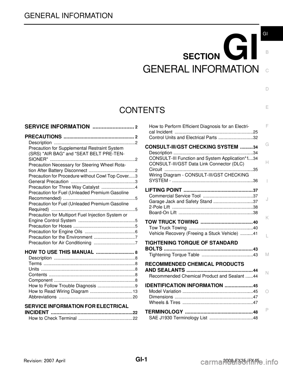
SERVICE INFORMATION .. ..........................2
PRECAUTIONS .............................................. .....2
Description .......................................................... ......2
Precaution for Supplemental Restraint System
(SRS) "AIR BAG" and "SEAT BELT PRE-TEN-
SIONER" ...................................................................
2
Precaution Necessary for Steering Wheel Rota-
tion After Battery Disconnect .....................................
2
Precaution for Procedure without Cowl Top Cover ......3
General Precaution ...................................................3
Precaution for Three Way Catalyst ...........................4
Precaution for Fuel (Unleaded Premium Gasoline
Recommended) .........................................................
5
Precaution for Fuel (Unleaded Premium Gasoline
Required) ..................................................................
5
Precaution for Multiport Fuel Injection System or
Engine Control System .............................................
5
Precaution for Hoses .................................................5
Precaution for Engine Oils ........................................6
Precaution for the Environment .................................7
Precaution for Air Conditioning .................................7
HOW TO USE THIS MANUAL ............................8
Description .......................................................... ......8
Terms ........................................................................8
Units ..........................................................................8
Contents ....................................................................8
Component ................................................................8
How to Follow Trouble Diagnosis ..............................9
How to Read Wiring Diagram ..................................13
Abbreviations ..........................................................20
SERVICE INFORMATION FOR ELECTRICAL
INCIDENT ...........................................................
22
How to Check Terminal ....................................... ....22
How to Perform Efficient Diagnosis for an Electri-
cal Incident .......................................................... ....
25
Control Units and Electrical Parts ............................32
CONSULT-III/GST CHECKING SYSTEM .........34
Description ...............................................................34
CONSULT-III Function and System Application*1 ....34
CONSULT-III/GST Data Link Connector (DLC)
Circuit ......................................................................
35
Wiring Diagram - CONSULT-III/GST CHECKING
SYSTEM - ................................................................
36
LIFTING POINT .................................................37
Commercial Service Tool ........................................37
Garage Jack and Safety Stand ................................37
2-Pole Lift ................................................................38
Board-On Lift ...........................................................38
TOW TRUCK TOWING .....................................40
Tow Truck Towing ...................................................40
Vehicle Recovery (Freeing a Stuck Vehicle) ...........41
TIGHTENING TORQUE OF STANDARD
BOLTS ...............................................................
43
Tightening Torque Table .........................................43
RECOMMENDED CHEMICAL PRODUCTS
AND SEALANTS ...............................................
44
Recommended Chemical Product and Sealant .......44
IDENTIFICATION INFORMATION ....................45
Model Variation ........................................................45
Dimensions ..............................................................47
Wheels & Tires ........................................................47
TERMINOLOGY ................................................48
SAE J1930 Terminology List ...................................48
3AA93ABC3ACD3AC03ACA3AC03AC63AC53A913A773A893A873A873A8E3A773A983AC73AC93AC03AC3
3A893A873A873A8F3A773A9D3AAF3A8A3A8C3A863A9D3AAF3A8B3A8C
Page 2909 of 3924

IDENTIFICATION INFORMATIONGI-47
< SERVICE INFORMATION >
C
DE
F
G H
I
J
K L
M B
GI
N
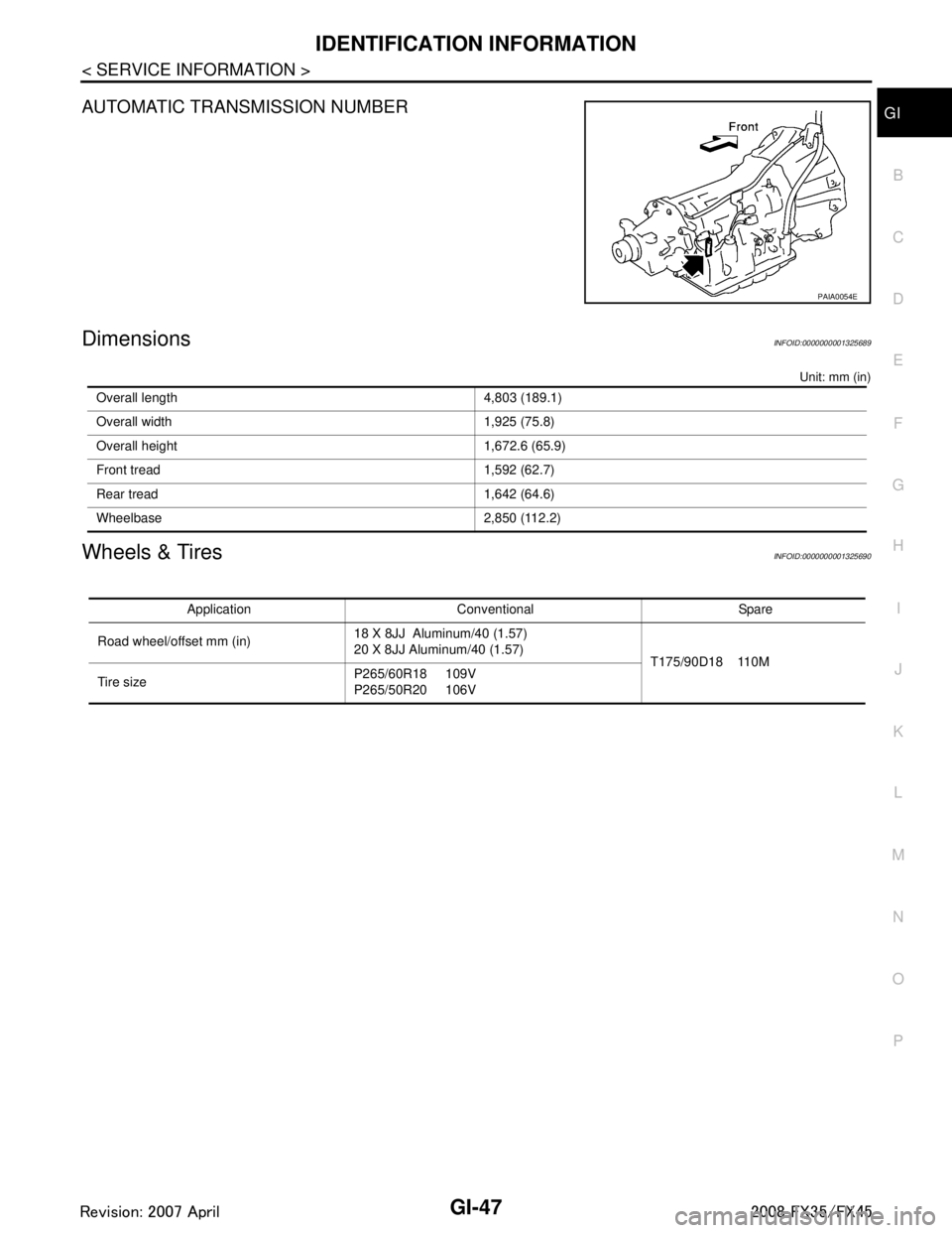
O PAUTOMATIC TRANSMISSION NUMBER
DimensionsINFOID:0000000001325689
Unit: mm (in)
Wheels & TiresINFOID:0000000001325690
PAIA0054E
Overall length 4,803 (189.1)
Overall width 1,925 (75.8)
Overall height 1,672.6 (65.9)
Front tread 1,592 (62.7)
Rear tread 1,642 (64.6)
Wheelbase 2,850 (112.2)
Application Conventional Spare
Road wheel/offset mm (in) 18 X 8JJ Aluminum/40 (1.57)
20 X 8JJ Aluminum/40 (1.57)
T175/90D18 110M
Tire size P265/60R18 109V
P265/50R20 106V
3AA93ABC3ACD3AC03ACA3AC03AC63AC53A913A773A893A873A873A8E3A773A983AC73AC93AC03AC3
3A893A873A873A8F3A773A9D3AAF3A8A3A8C3A863A9D3AAF3A8B3A8C