2008 INFINITI FX35 stop start
[x] Cancel search: stop startPage 3427 of 3924

HARNESSPG-63
< SERVICE INFORMATION >
C
DE
F
G H
I
J
L
M A
B
PG
N
O P
PHSB1 EC Camshaft Position Sensor (PHASE) (Bank 1)
PHSB2 EC Camshaft Position Sensor (PHASE) (Bank 2)
PNP/SW AT Park/Neutral Position Switch
PNP/SW EC Park/Neutral Position Switch
POS EC Crankshaft Position Sensor (CKPS) (POS)
POWER PG Power Supply Routing
PRE/SE EC EVAP Control System Pressure Sensor
PS/SEN EC Power Steering Pressure Sensor
R/VIEW DI Rear View Ca mera Control System
ROOM/L LT Interior Room Lamp
RP/SEN EC Refrigerant Pressure Sensor
SEAT SE Power Seat
SEN/PW EC Sensor Power Supply
SHIFT AT A/T Shift Lock System
SNOWSW EC Snow Mode Switch
SROOF RF Sunroof
SRS SRS Supplemental Restraint System
START SC Starting System
STOP/L LT Stop Lamp
STSIG AT Start Signal Circuit
T/WARN WT Low Tire Pressure Warning System
TAIL/L LT Parking, License and Tail Lamps
TPS1 EC Throttle Position Sensor (Sensor 1)
TPS2 EC Throttle Position Sensor (Sensor 2)
TPS3 EC Throttle Position Sensor
TRNSCV BL Homelink Universal Transceiver
TURN LT Turn Signal and Hazard Warning Lamp
VDC BRC Vehicle Dynamics Control System
VEHSEC BL Vehicle Security System
VENT/V EC EVAP Canister Vent Control Valve
VIAS EC Variable Induction Air Control System
VIAS/V EC VIAS Control Solenoid Valve
VSSA/T AT Vehicle Sp eed Sensor A/T (Revolution Sensor)
WARN DI Warning Lamps
WINDOW GW Power Window
WIP/R WW Rear Wiper and Washer
WIPER WW Front Wiper and Washer Code Section Wiring Diagram Name
3AA93ABC3ACD3AC03ACA3AC03AC63AC53A913A773A893A873A873A8E3A773A983AC73AC93AC03AC3
3A893A873A873A8F3A773A9D3AAF3A8A3A8C3A863A9D3AAF3A8B3A8C
Page 3521 of 3924

RF-6
< SERVICE INFORMATION >
SQUEAK AND RATTLE TROUBLE DIAGNOSES
Insulates where slight movement is present. Ideal for instrument panel applications.
SILICONE GREASE
Used in place of UHMW tape that will be visible or not fit.
Note: Will only last a few months.
SILICONE SPRAY
Use when grease cannot be applied.
DUCT TAPE
Use to eliminate movement.
CONFIRM THE REPAIR
Confirm that the cause of a noise is repaired by test driving the vehicle. Operate the vehicle under the same
conditions as when the noise originally occurred. Refer to the notes on the Diagnostic Worksheet.
Generic Squeak and Rattle TroubleshootingINFOID:0000000001328031
Refer to Table of Contents for specific component removal and installation information.
INSTRUMENT PANEL
Most incidents are caused by contact and movement between:
1. Cluster lid A and instrument panel
2. Acrylic lens and combination meter housing
3. Instrument panel to front pillar garnish
4. Instrument panel to windshield
5. Instrument panel mounting pins
6. Wiring harnesses behind the combination meter
7. A/C defroster duct and duct joint
These incidents can usually be located by tapping or moving the components to duplicate the noise or by
pressing on the components while driving to stop the noi se. Most of these incidents can be repaired by apply-
ing felt cloth tape or silicon spray (in hard to reach areas).Urethane pads can be used to insulate wiring har-
ness.
CAUTION:
Do not use silicone spray to isolate a squeak or ra ttle. If you saturate the area with silicone, you will
not be able to recheck the repair.
CENTER CONSOLE
Components to pay attention to include:
1. Shifter assembly cover to finisher
2. A/C control unit and cluster lid C
3. Wiring harnesses behind audio and A/C control unit
The instrument panel repair and isolation pr ocedures also apply to the center console.
DOORS
Pay attention to the:
1. Finisher and inner panel making a slapping noise
2. Inside handle escutcheon to door finisher
3. Wiring harnesses tapping
4. Door striker out of alignment causing a popping noise on starts and stops
Tapping or moving the components or pressing on them wh ile driving to duplicate the conditions can isolate
many of these incidents. You can usually insulate the areas with felt cloth tape or insulator foam blocks from
the Nissan Squeak and Rattle Kit (J43980) to repair the noise.
TRUNK
Trunk noises are often caused by a loose jack or loose items put into the trunk by the owner.
In addition look for:
1. Trunk lid dumpers out of adjustment
2. Trunk lid striker out of adjustment
3. Trunk lid torsion bars knocking together
4. A loose license plate or bracket
3AA93ABC3ACD3AC03ACA3AC03AC63AC53A913A773A893A873A873A8E3A773A983AC73AC93AC03AC3
3A893A873A873A8F3A773A9D3AAF3A8A3A8C3A863A9D3AAF3A8B3A8C
Page 3551 of 3924

DIFFERENTIAL GEAR OILRFD-9
< SERVICE INFORMATION >
CEF
G H
I
J
K L
M A
B
RFD
N
O P
DIFFERENTIAL GEAR OIL
Changing Differential Gear OilINFOID:0000000001327495
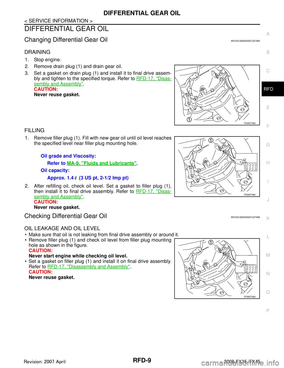
DRAINING
1. Stop engine.
2. Remove drain plug (1) and drain gear oil.
3. Set a gasket on drain plug (1) and install it to final drive assem- bly and tighten to the specified torque. Refer to RFD-17, "
Disas-
sembly and Assembly".
CAUTION:
Never reuse gasket.
FILLING
1. Remove filler plug (1). Fill with new gear oil until oil level reaches the specified level near filler plug mounting hole.
2. After refilling oil, check oil level. Set a gasket to filler plug (1), then install it to final drive assembly. Refer to RFD-17, "
Disas-
sembly and Assembly".
CAUTION:
Never reuse gasket.
Checking Differential Gear OilINFOID:0000000001327496
OIL LEAKAGE AND OIL LEVEL
Make sure that oil is not leaking from final drive assembly or around it.
Remove filler plug (1) and check oil level from filler plug mounting hole as shown in the figure.
CAUTION:
Never start engine while checking oil level.
Set a gasket on filler plug (1) and install it on final drive assembly.
Refer to RFD-17, "
Disassembly and Assembly".
CAUTION:
Never reuse gasket.
PDIA0748J
Oil grade and Viscosity:
Refer to MA-9, "
Fluids and Lubricants".
Oil capacity:
Approx. 1.4 (3 US pt, 2-1/2 Imp pt)
PDIA0749J
PDIA0749J
3AA93ABC3ACD3AC03ACA3AC03AC63AC53A913A773A893A873A873A8E3A773A983AC73AC93AC03AC3
3A893A873A873A8F3A773A9D3AAF3A8A3A8C3A863A9D3AAF3A8B3A8C
Page 3625 of 3924

SC-16
< SERVICE INFORMATION >
STARTING SYSTEM
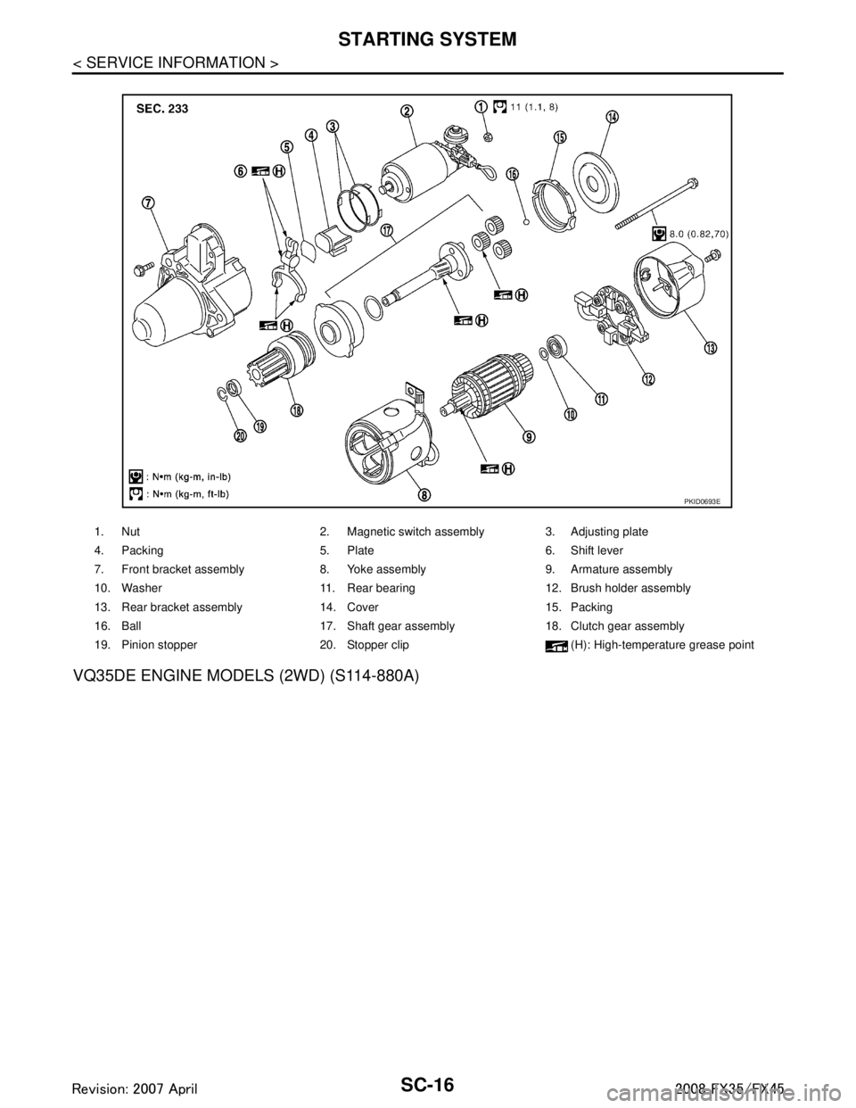
VQ35DE ENGINE MODELS (2WD) (S114-880A)
1. Nut 2. Magnetic switch assembly 3. Adjusting plate
4. Packing 5. Plate 6. Shift lever
7. Front bracket assembly 8. Yoke assembly 9. Armature assembly
10. Washer 11. Rear bearing 12. Brush holder assembly
13. Rear bracket assembly 14. Cover 15. Packing
16. Ball 17. Shaft gear assembly 18. Clutch gear assembly
19. Pinion stopper 20. Stopper clip (H): High-temperature grease point
PKID0693E
3AA93ABC3ACD3AC03ACA3AC03AC63AC53A913A773A893A873A873A8E3A773A983AC73AC93AC03AC3
3A893A873A873A8F3A773A9D3AAF3A8A3A8C3A863A9D3AAF3A8B3A8C
Page 3639 of 3924

SC-30
< SERVICE INFORMATION >
SERVICE DATA AND SPECIFICATIONS (SDS)
SERVICE DATA AND SPECIFICATIONS (SDS)
BatteryINFOID:0000000001328260
StarterINFOID:0000000001328261
AlternatorINFOID:0000000001328262
Typ e11 0 D 2 6 L
Capacity V - AH 12 - 75
Cold cranking current (F or reference value) A 720
Applied model VK45DE VQ3 5DE (2WD) VQ35DE (AWD)
Ty p e M002T85075 S114-880A S114-881A
MITSUBISHI make HITACHI make Reduction gear type
System voltage V 12
No-load Te r m i n a l v o l t a g e V 11
Current A Less than 145 Less than 90
Revolution rpm More than 3,300 More than 2,880
Minimum diameter of commutator mm (in) 31.4 (1.236) 28.0 (1.102)
Minimum length of brush mm (in) 11.0 (0.433) 10.5 (0.413)
Brush spring tension N (kg, lb) 26.7 - 36.1
(2.72 - 3.68,
6.80 - 8.12) 16.2 (1.65, 3.6)
Clearance between bearing metal and armature shaft mm (in) Less than 0.2 (0.008)
Clearance between pinion front edge and pinion stopper mm (in) 0.5 - 2.0
(0.020 - 0.079) —
Movement in height of pinion assembly mm (in) — 0.3 - 2.5 (0.012 - 0.098)
Applied model VK45DE VQ35DE
Ty p e LR1110 - 716B A3TG0191
HITACHI make MITSUBISHI make
Nominal rating V - A 12 - 110
Ground polarity Negative
Minimum revolution under no-load (When 13.5 V is applied) rpm Less than 1,100 Less than 1,000
Hot output current (When 13.5 V is applied) A/rpm More than 70/1,800
More than 91/2,500
More than 110/5,000 More than 37/1,300
More than 92/2,500
More than 103/5,000
Regulated output voltage V 14.1 - 14.7
Minimum length of brush mm (in) More than 6.00 (0.236) More than 5.00 (0.197)
Brush spring pressure N (g, oz) 1.00 - 3.43
(102 - 350, 3.60 - 12.34) 4.8 - 6.0
(490 - 612, 17.28 - 21.60)
Slip ring minimum outer diameter mm (in) More than 26.0 (1.024) More than 22.1 (0.870)
Rotor (Field coil) resistance Ω2.31 1.7 - 2.1
3AA93ABC3ACD3AC03ACA3AC03AC63AC53A913A773A893A873A873A8E3A773A983AC73AC93AC03AC3
3A893A873A873A8F3A773A9D3AAF3A8A3A8C3A863A9D3AAF3A8B3A8C
Page 3647 of 3924

SE-8
< SERVICE INFORMATION >
SQUEAK AND RATTLE TROUBLE DIAGNOSES
Insulates where slight movement is present. Ideal for instrument panel applications.
SILICONE GREASE
Used in place of UHMW tape that will be visible or not fit.
Note: Will only last a few months.
SILICONE SPRAY
Use when grease cannot be applied.
DUCT TAPE
Use to eliminate movement.
CONFIRM THE REPAIR
Confirm that the cause of a noise is repaired by test driving the vehicle. Operate the vehicle under the same
conditions as when the noise originally occurred. Refer to the notes on the Diagnostic Worksheet.
Generic Squeak and Rattle TroubleshootingINFOID:0000000001328095
Refer to Table of Contents for specific component removal and installation information.
INSTRUMENT PANEL
Most incidents are caused by contact and movement between:
1. The cluster lid A and instrument panel
2. Acrylic lens and combination meter housing
3. Instrument panel to front pillar garnish
4. Instrument panel to windshield
5. Instrument panel mounting pins
6. Wiring harnesses behind the combination meter
7. A/C defroster duct and duct joint
These incidents can usually be located by tapping or moving the components to duplicate the noise or by
pressing on the components while driving to stop the noi se. Most of these incidents can be repaired by apply-
ing felt cloth tape or silicon spray (in hard to reach areas). Urethane pads can be used to insulate wiring har-
ness.
CAUTION:
Do not use silicone spray to isolate a squeak or ra ttle. If you saturate the area with silicone, you will
not be able to recheck the repair.
CENTER CONSOLE
Components to pay attention to include:
1. Shifter assembly cover to finisher
2. A/C control unit and cluster lid C
3. Wiring harnesses behind audio and A/C control unit
The instrument panel repair and isolation pr ocedures also apply to the center console.
DOORS
Pay attention to the:
1. Finisher and inner panel making a slapping noise
2. Inside handle escutcheon to door finisher
3. Wiring harnesses tapping
4. Door striker out of alignment causing a popping noise on starts and stops
Tapping or moving the components or pressing on them wh ile driving to duplicate the conditions can isolate
many of these incidents. You can usually insulate the areas with felt cloth tape or insulator foam blocks from
the Nissan Squeak and Rattle Kit (J-43980) to repair the noise.
TRUNK
Trunk noises are often caused by a loose jack or loose items put into the trunk by the owner.
In addition look for:
1. Trunk lid dumpers out of adjustment
2. Trunk lid striker out of adjustment
3. The trunk lid torsion bars knocking together
4. A loose license plate or bracket
3AA93ABC3ACD3AC03ACA3AC03AC63AC53A913A773A893A873A873A8E3A773A983AC73AC93AC03AC3
3A893A873A873A8F3A773A9D3AAF3A8A3A8C3A863A9D3AAF3A8B3A8C
Page 3651 of 3924

SE-12
< SERVICE INFORMATION >
AUTOMATIC DRIVE POSITIONER
AUTOMATIC DRIVE POSITIONER
System DescriptionINFOID:0000000001328097
The system automatically moves the driver seat to facilitate entry/exit to/from the vehicle. The automatic
drive positioner control unit can also store the optimum driving positions (driver seat, steering wheel position
(tilt, telescopic) and door mirror position) for 2 people. If the driver is changes, one-touch operation allows
changing to the other driving position.
The settings (ON/OFF) of the automatic sliding s eat (Entry/Exiting operation) at entry/exit can be changed
as desired, using the display unit in the center of the instrument panel. The set content is transmitted by
CAN communication, from display contro l unit to driver seat control unit.
Using CONSULT-III, the seat slide and steering wheel amount at entry/exit setting can be changed.
MANUAL OPERATION
The driving position [seat position, steering wheel posit ion (tilt, telescopic) and door mirror position] can be
adjusted with the power seat switch or ADP steering switch or door mirror remote control switch.
NOTE:
The seat can be manually operated with the ignition switch OFF.
The door mirrors can be manually operated with the ignition switch turned ACC or ON.
AUTOMATIC OPERATION
NOTE:
Disconnecting the battery erases the stored memory.
After connecting the battery, insert the key into the ignition cylinder and turn the driver door switch ON (open) →OFF (close) →ON
(open), the Entry/ Exiting operation becomes possible.
After exiting operation is carried out, return operation can be operated.
NOTE:
During automatic operation, if the ignition switch is turned ON →START, the automatic operation is suspended. When the ignition switch
returns to ON, it resumes.
MEMORY STORING AND KEYFOB INTERLOCK STORING
Store the 2 driving positions and shifts to t he stored driving position with the memory switch.
Function Description
Memory switch operation The seat, steering and door mirror move to the stored driving position by pushing
memory switch (1 or 2).
Entry/Exiting function Exiting operation At exit, the seat moves backward and steering wheel moves forward/upward.
Entry operation
At entry, the seat and steering wheel returns from the exiting position to the previous
driving position.
keyfob interlock operation Perform memory operation, exiting operation and entry operation by pressing keyfob
unlock button.
Auto operation temporary stop
conditions. When ignition switch turned to START during memory switch operation and return opera-
tion, memory switch operation and entry operation is stopped.
Auto operation stop conditions. When the vehicle speed becomes 7 km/h (4 MPH) or higher.
When the setting switch, memory switch 1, or 2 are pressed.
When A/T selector lever is in any position other than P.
When the door mirror remote control switch is operated (when ignition switch turned to
ON or ACC).
When power seat switch turned ON.
When ADP steering switch turned ON (telescopic operation or tilt operation).
When door mirror operates (only memory switch operation).
When driver seat sliding Entry/Exiting setting is OFF (only entry/exiting operation).
When steering wheel tilt and telescopic Entry/Exiting setting is OFF (only entry/exiting op-
eration).
When the tilt and telescopic sensor malfunction is detected.
3AA93ABC3ACD3AC03ACA3AC03AC63AC53A913A773A893A873A873A8E3A773A983AC73AC93AC03AC3
3A893A873A873A8F3A773A9D3AAF3A8A3A8C3A863A9D3AAF3A8B3A8C
Page 3797 of 3924

AWD SYSTEMTF-11
< SERVICE INFORMATION >
CEF
G H
I
J
K L
M A
B
TF
N
O P
AWD SYSTEM
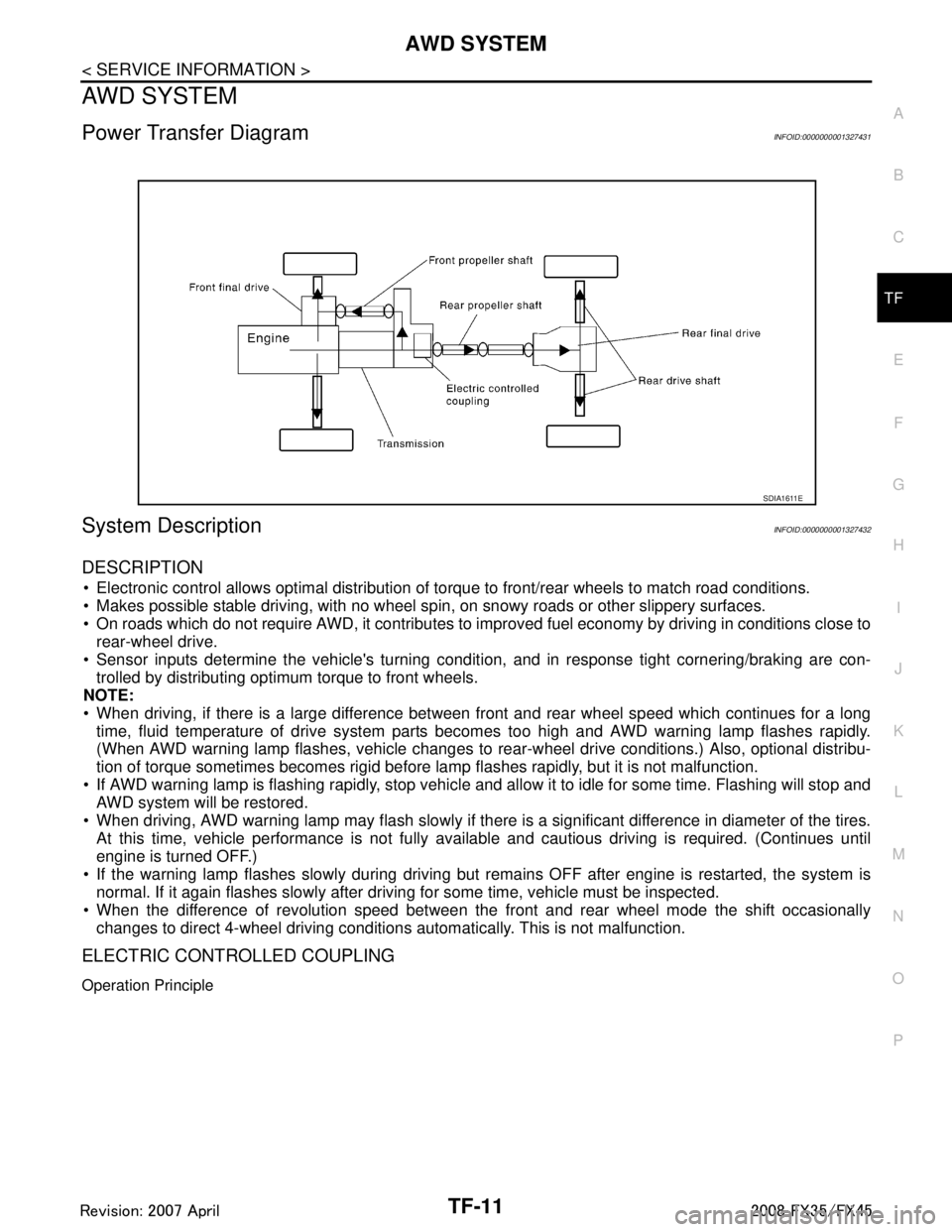
Power Transfer DiagramINFOID:0000000001327431
System DescriptionINFOID:0000000001327432
DESCRIPTION
Electronic control allows optimal distribution of torque to front/rear wheels to match road conditions.
Makes possible stable driving, with no wheel sp in, on snowy roads or other slippery surfaces.
On roads which do not require AWD, it contributes to improved fuel economy by driving in conditions close to
rear-wheel drive.
Sensor inputs determine the vehicle's turning conditi on, and in response tight cornering/braking are con-
trolled by distributing optimum torque to front wheels.
NOTE:
When driving, if there is a large difference between front and rear wheel speed which continues for a long
time, fluid temperature of drive system parts becom es too high and AWD warning lamp flashes rapidly.
(When AWD warning lamp flashes, vehicle changes to r ear-wheel drive conditions.) Also, optional distribu-
tion of torque sometimes becomes rigid before lamp flashes rapidly, but it is not malfunction.
If AWD warning lamp is flashing rapidly, stop vehicle and allow it to idle for some time. Flashing will stop and AWD system will be restored.
When driving, AWD warning lamp may flash slowly if ther e is a significant difference in diameter of the tires.
At this time, vehicle performance is not fully avail able and cautious driving is required. (Continues until
engine is turned OFF.)
If the warning lamp flashes slowly during driving but remains OFF after engine is restarted, the system is
normal. If it again flashes slowly after driving for some time, vehicle must be inspected.
When the difference of revolution speed between the front and rear wheel mode the shift occasionally
changes to direct 4-wheel driving conditions automatically. This is not malfunction.
ELECTRIC CONTROLLED COUPLING
Operation Principle
SDIA1611E
3AA93ABC3ACD3AC03ACA3AC03AC63AC53A913A773A893A873A873A8E3A773A983AC73AC93AC03AC3
3A893A873A873A8F3A773A9D3AAF3A8A3A8C3A863A9D3AAF3A8B3A8C