2008 INFINITI FX35 turn signal bulb
[x] Cancel search: turn signal bulbPage 3192 of 3924
LT-90
< SERVICE INFORMATION >
TURN SIGNAL AND HAZARD WARNING LAMPS
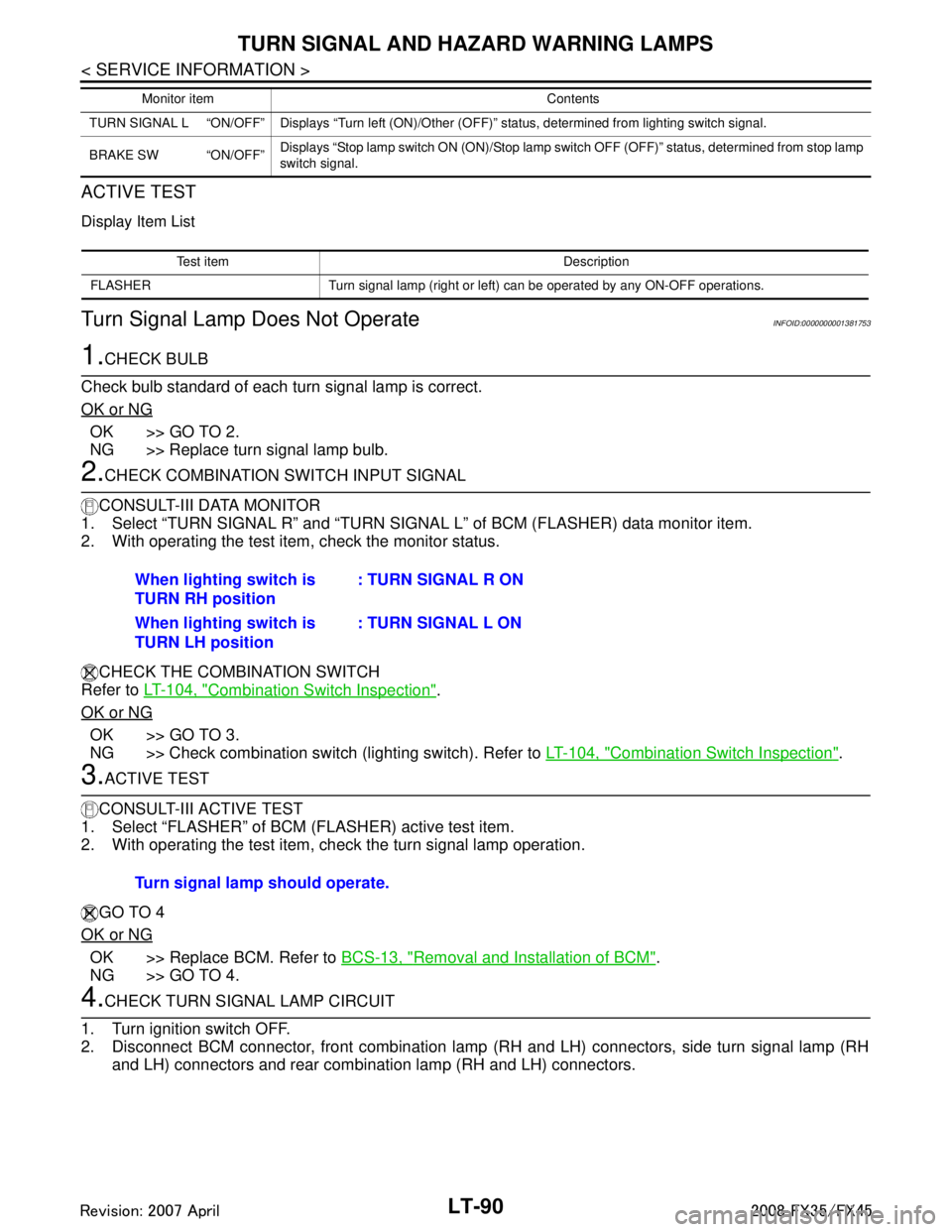
ACTIVE TEST
Display Item List
Turn Signal Lamp Does Not OperateINFOID:0000000001381753
1.CHECK BULB
Check bulb standard of each turn signal lamp is correct.
OK or NG
OK >> GO TO 2.
NG >> Replace turn signal lamp bulb.
2.CHECK COMBINATION SWITCH INPUT SIGNAL
CONSULT-III DATA MONITOR
1. Select “TURN SIGNAL R” and “TURN SIGNAL L” of BCM (FLASHER) data monitor item.
2. With operating the test item, check the monitor status.
CHECK THE COMBINATION SWITCH
Refer to LT-104, "
Combination Switch Inspection".
OK or NG
OK >> GO TO 3.
NG >> Check combination switch (lighting switch). Refer to LT-104, "
Combination Switch Inspection".
3.ACTIVE TEST
CONSULT-III ACTIVE TEST
1. Select “FLASHER” of BCM (FLASHER) active test item.
2. With operating the test item, check the turn signal lamp operation.
GO TO 4
OK or NG
OK >> Replace BCM. Refer to BCS-13, "Removal and Installation of BCM".
NG >> GO TO 4.
4.CHECK TURN SIGNAL LAMP CIRCUIT
1. Turn ignition switch OFF.
2. Disconnect BCM connector, front combination lamp (RH and LH) connectors, side turn signal lamp (RH and LH) connectors and rear combination lamp (RH and LH) connectors.
TURN SIGNAL L “ON/OFF” Displays “Turn left (ON)/Other (O FF)” status, determined from lighting switch signal.
BRAKE SW “ON/OFF” Displays “Stop lamp switch ON (ON)/Stop lamp switch OFF (OFF)” status, determined from stop lamp
switch signal.
Monitor item Contents
Test item Description
FLASHER Turn signal lamp (right or left) can be operated by any ON-OFF operations.
When lighting switch is
TURN RH position : TURN SIGNAL R ON
When lighting switch is
TURN LH position : TURN SIGNAL L ON
Turn signal lamp should operate.
3AA93ABC3ACD3AC03ACA3AC03AC63AC53A913A773A893A873A873A8E3A773A983AC73AC93AC03AC3
3A893A873A873A8F3A773A9D3AAF3A8A3A8C3A863A9D3AAF3A8B3A8C
Page 3197 of 3924
TURN SIGNAL AND HAZARD WARNING LAMPSLT-95
< SERVICE INFORMATION >
C
DE
F
G H
I
J
L
M A
B
LT
N
O P
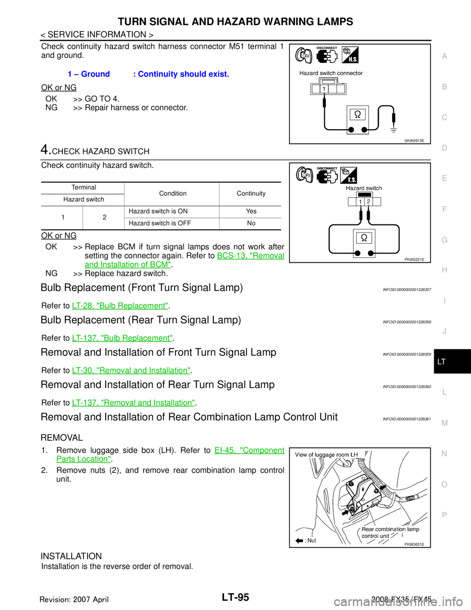
Check continuity hazard switch harness connector M51 terminal 1
and ground.
OK or NG
OK >> GO TO 4.
NG >> Repair harness or connector.
4.CHECK HAZARD SWITCH
Check continuity hazard switch.
OK or NG
OK >> Replace BCM if turn signal lamps does not work after setting the connector again. Refer to BCS-13, "
Removal
and Installation of BCM".
NG >> Replace hazard switch.
Bulb Replacement (Fr ont Turn Signal Lamp)INFOID:0000000001328357
Refer to LT-28, "Bulb Replacement".
Bulb Replacement (Rear Turn Signal Lamp)INFOID:0000000001328358
Refer to LT-137, "Bulb Replacement".
Removal and Installation of Front Turn Signal LampINFOID:0000000001328359
Refer to LT-30, "Removal and Installation".
Removal and Installation of Rear Turn Signal LampINFOID:0000000001328360
Refer to LT-137, "Removal and Installation".
Removal and Installation of Rear Combination Lamp Control UnitINFOID:0000000001328361
REMOVAL
1. Remove luggage side box (LH). Refer to EI-45, "Component
Parts Location".
2. Remove nuts (2), and remove rear combination lamp control unit.
INSTALLATION
Installation is the reverse order of removal. 1 – Ground : Continuity should exist.
SKIA5913E
Te r m i n a l
Condition Continuity
Hazard switch
12 Hazard switch is ON Yes
Hazard switch is OFF No
PKIA5221E
PKIB3631E
3AA93ABC3ACD3AC03ACA3AC03AC63AC53A913A773A893A873A873A8E3A773A983AC73AC93AC03AC3
3A893A873A873A8F3A773A9D3AAF3A8A3A8C3A863A9D3AAF3A8B3A8C
Page 3216 of 3924
LT-114
< SERVICE INFORMATION >
STOP LAMP
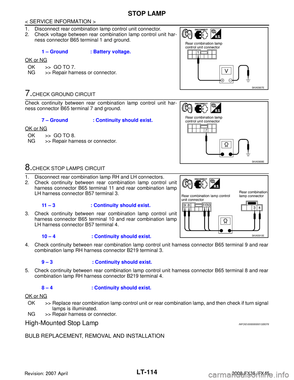
1. Disconnect rear combination lamp control unit connector.
2. Check voltage between rear combination lamp control unit har-ness connector B65 terminal 1 and ground.
OK or NG
OK >> GO TO 7.
NG >> Repair harness or connector.
7.CHECK GROUND CIRCUIT
Check continuity between rear combination lamp control unit har-
ness connector B65 terminal 7 and ground.
OK or NG
OK >> GO TO 8.
NG >> Repair harness or connector.
8.CHECK STOP LAMPS CIRCUIT
1. Disconnect rear combination lamp RH and LH connectors.
2. Check continuity between rear combination lamp control unit harness connector B65 terminal 11 and rear combination lamp
LH harness connector B57 terminal 3.
3. Check continuity between rear combination lamp control unit harness connector B65 terminal 10 and rear combination lamp
LH harness connector B57 terminal 4.
4. Check continuity between rear combination lamp control unit harness connector B65 terminal 9 and rear combination lamp RH harness connector B219 terminal 3.
5. Check continuity between rear combination lamp control unit harness connector B65 terminal 8 and rear combination lamp RH harness connector B219 terminal 4.
OK or NG
OK >> Replace rear combination lamp control unit or rear combination lamp, and then check if turn signal
lamps is illuminated.
NG >> Repair harness or connector.
High-Mounted Stop LampINFOID:0000000001328376
BULB REPLACEMENT, REMOVAL AND INSTALLATION
1 – Ground : Battery voltage.
SKIA5907E
7 – Ground : Continuity should exist.
SKIA5908E
11 – 3 : Continuity should exist.
10 – 4 : Continuity should exist.
9 – 3 : Continuity should exist.
8 – 4 : Continuity should exist.
SKIA5910E
3AA93ABC3ACD3AC03ACA3AC03AC63AC53A913A773A893A873A873A8E3A773A983AC73AC93AC03AC3
3A893A873A873A8F3A773A9D3AAF3A8A3A8C3A863A9D3AAF3A8B3A8C
Page 3235 of 3924
PARKING, LICENSE PLATE AND TAIL LAMPS
LT-133
< SERVICE INFORMATION >
C
D E
F
G H
I
J
L
M A
B
LT
N
O P
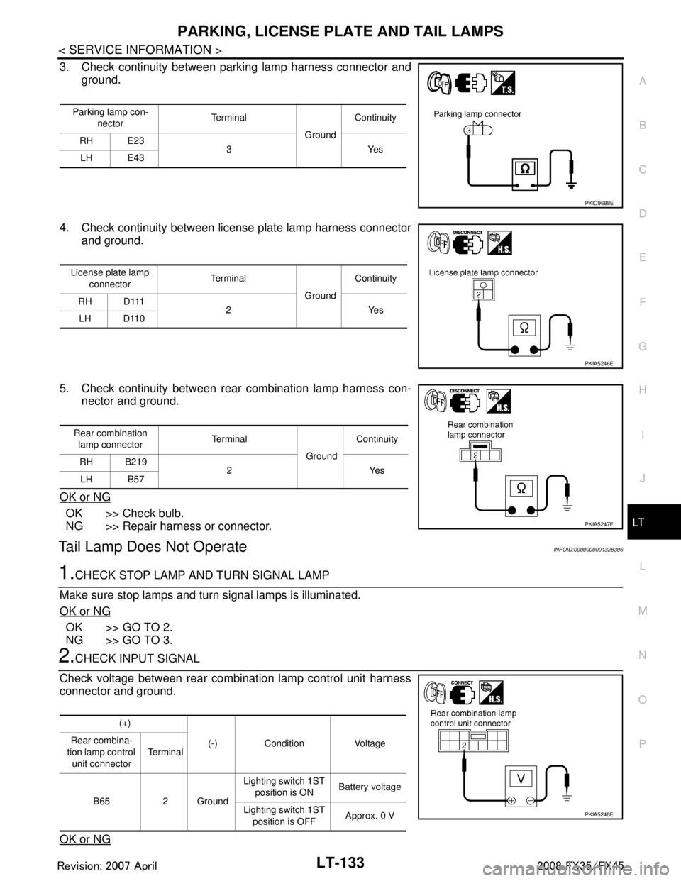
3. Check continuity between parking lamp harness connector and ground.
4. Check continuity between license plate lamp harness connector and ground.
5. Check continuity between rear combination lamp harness con- nector and ground.
OK or NG
OK >> Check bulb.
NG >> Repair harness or connector.
Tail Lamp Does Not OperateINFOID:0000000001328396
1.CHECK STOP LAMP AND TURN SIGNAL LAMP
Make sure stop lamps and turn signal lamps is illuminated.
OK or NG
OK >> GO TO 2.
NG >> GO TO 3.
2.CHECK INPUT SIGNAL
Check voltage between rear combination lamp control unit harness
connector and ground.
OK or NG
Parking lamp con- nector Te r m i n a l
GroundContinuity
RH E23 3Yes
LH E43
PKIC9688E
License plate lamp
connector Te r m i n a l
GroundContinuity
RH D111 2Yes
LH D110
PKIA5246E
Rear combination
lamp connector Te r m i n a l
GroundContinuity
RH B219 2Yes
LH B57
PKIA5247E
(+)
(-) Condition Voltage
Rear combina-
tion lamp control unit connector Te r m i n a l
B65 2 Ground Lighting switch 1ST
position is ON Battery voltage
Lighting switch 1ST position is OFF Approx. 0 V
PKIA5248E
3AA93ABC3ACD3AC03ACA3AC03AC63AC53A913A773A893A873A873A8E3A773A983AC73AC93AC03AC3
3A893A873A873A8F3A773A9D3AAF3A8A3A8C3A863A9D3AAF3A8B3A8C
Page 3239 of 3924
REAR COMBINATION LAMPLT-137
< SERVICE INFORMATION >
C
DE
F
G H
I
J
L
M A
B
LT
N
O P
REAR COMBINATION LAMP
Bulb ReplacementINFOID:0000000001328404
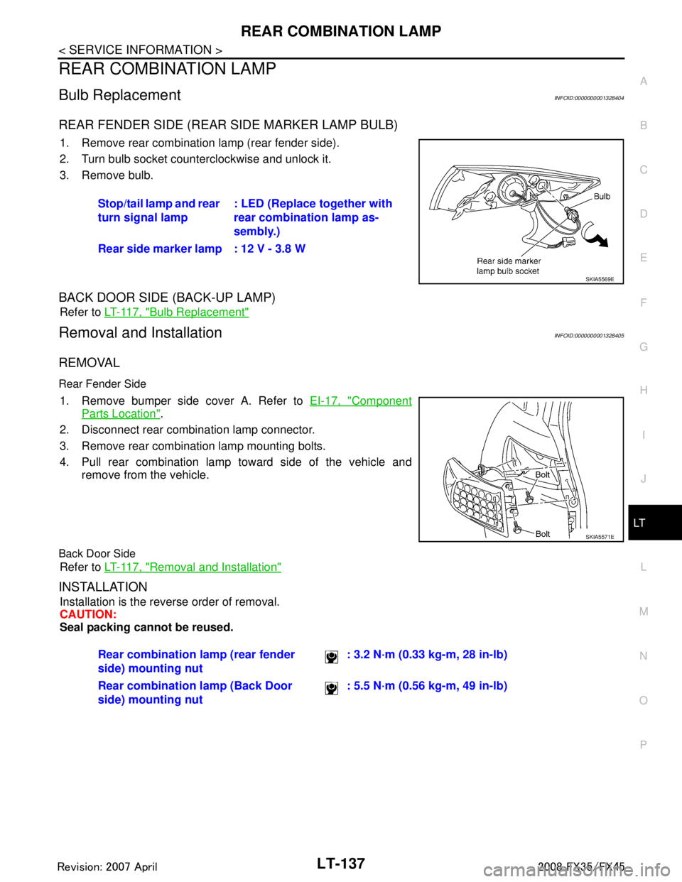
REAR FENDER SIDE (REAR SIDE MARKER LAMP BULB)
1. Remove rear combination lamp (rear fender side).
2. Turn bulb socket counterclockwise and unlock it.
3. Remove bulb.
BACK DOOR SIDE (BACK-UP LAMP)
Refer to LT-117, "Bulb Replacement"
Removal and InstallationINFOID:0000000001328405
REMOVAL
Rear Fender Side
1. Remove bumper side cover A. Refer to EI-17, "Component
Parts Location".
2. Disconnect rear combination lamp connector.
3. Remove rear combination lamp mounting bolts.
4. Pull rear combination lamp toward side of the vehicle and remove from the vehicle.
Back Door Side
Refer to LT-117, "Removal and Installation"
INSTALLATION
Installation is the reverse order of removal.
CAUTION:
Seal packing cannot be reused.Stop/tail lamp and rear
turn signal lamp
: LED (Replace together with
rear combination lamp as-
sembly.)
Rear side marker lamp : 12 V - 3.8 W
SKIA5569E
SKIA5571E
Rear combination lamp (rear fender
side) mounting nut : 3.2 N·m (0.33 kg-m, 28 in-lb)
Rear combination lamp (Back Door
side) mounting nut : 5.5 N·m (0.56 kg-m, 49 in-lb)
3AA93ABC3ACD3AC03ACA3AC03AC63AC53A913A773A893A873A873A8E3A773A983AC73AC93AC03AC3
3A893A873A873A8F3A773A9D3AAF3A8A3A8C3A863A9D3AAF3A8B3A8C
Page 3285 of 3924

BULB SPECIFICATIONSLT-183
< SERVICE INFORMATION >
C
DE
F
G H
I
J
L
M A
B
LT
N
O P
BULB SPECIFICATIONS
HeadlampINFOID:0000000001328429
Exterior LampINFOID:0000000001328430
Interior Lamp/IlluminationINFOID:0000000001328431
Item Wattage (W)
High/Low (Xenon type) 35 (D2S)
Item Wattage (W)
Front combination lamp Front turn signal lamp 21 (amber)
Daytime/Parking lamp 21/5
Front side marker lamp 3.8
Rear combination lamp Stop/Tail lamp and Rear Turn signal lamp LED
Rear side marker lamp 3.8
Front fog lamp 35 (H8)
Back-up lamp 18
License plate lamp 5
High-mounted stop lamp (back door mount) LED
Item Wattage (W)
Map lamp 8
Interior room lamp 10
Personal lamp 8
Luggage room lamp 8
Step lamp 5
Glove box lamp 1.4
Vanity mirror lamp 1.32
Ignition key hole illumination 0.8
A/T device illumination lamp 1.4
Coin box illumination lamp 1.4
3AA93ABC3ACD3AC03ACA3AC03AC63AC53A913A773A893A873A873A8E3A773A983AC73AC93AC03AC3
3A893A873A873A8F3A773A9D3AAF3A8A3A8C3A863A9D3AAF3A8B3A8C
Page 3385 of 3924

IPDM E/R (INTELLIGENT POWER DISTRIBUTION MODULE ENGINE ROOM)
PG-21
< SERVICE INFORMATION >
C
D E
F
G H
I
J
L
M A
B
PG
N
O P
NOTE:
Turns ON-OFF the solenoid to switch Hi/Lo. In this case, the bulb does not illuminate.
Concept of Auto Active Test
IPDM E/R actuates auto active test mode when it re ceives door switch signal from BCM via CAN communi-
cation line. Therefore, when auto active test mode is activated successfully, CAN communication between
IPDM E/R and BCM is normal.
If any of systems controlled by IPDM E/R cannot be operated, possible cause can be easily diagnosed using
auto active test.
Diagnosis chart in auto active test mode
Symptom Inspection contents Possible cause
Any of front wipers, tail
and parking lamps, front
fog lamps, and head
lamps (Hi, Lo) do not op-
erate. Perform auto active
test. Does system in
question operate?YES BCM signal input system malfunction
NO Lamp/wiper motor malfunction
Lamp/wiper motor ground circuit malfunction
Harness/connector malfunction between IPDM E/R and system in question
IPDM E/R (integrated relay) malfunction
Rear window defogger
does not operate. Perform auto active
test. Does rear win-
dow defogger oper-
ate?YES BCM signal input circuit malfunction
NO Rear window defogger relay malfunction
Harness/connector malfunction between IPDM E/R and rear window de-
fogger relay.
Open circuit of rear window defogger
IPDM E/R malfunction
A/C compressor does
not operate. Perform auto active
test. Does magnetic
clutch operate?YES
BCM signal input circuit malfunction
CAN communication signal between BCM and ECM.
CAN communication signal between ECM and IPDM E/R
NO Magnetic clutch malfunction
Harness/connector malfunction between IPDM E/R and magnetic clutch
IPDM E/R (integrated relay) malfunction
Cooling fan does not op-
erate. Perform auto active
test. Does cooling
fan operate?YES
ECM signal input circuit
CAN communication signal between ECM and IPDM E/R
NO Cooling fan motor malfunction
Harness/connector malfunction between IPDM E/R and cooling fan motor
IPDM E/R (integrated relay) malfunction
Oil pressure warning
lamp does not operate. Perform auto active
test. Does oil pres-
sure warning lamp
blink?YES
Harness/connector malfunction between IPDM E/R and oil pressure switch
Oil pressure switch malfunction
IPDM E/R malfunction
NO CAN communication signal between BCM and unified meter and A/C amp.
Combination meter
3AA93ABC3ACD3AC03ACA3AC03AC63AC53A913A773A893A873A873A8E3A773A983AC73AC93AC03AC3
3A893A873A873A8F3A773A9D3AAF3A8A3A8C3A863A9D3AAF3A8B3A8C