2008 INFINITI FX35 torque
[x] Cancel search: torquePage 104 of 3924

A/T CONTROL SYSTEMAT-31
< SERVICE INFORMATION >
DE
F
G H
I
J
K L
M A
B
AT
N
O P
Input/Output Signal of TCMINFOID:0000000001327137
*1: Spare for vehicle speed sensor·A/T (revolution sensor)
*2: Spare for accelerator pedal position signal
*3: If these input and output signals are different, the TCM triggers the fail-safe function.
*4: Used as a condition for starting self-diagnostics; if self-diagnostics are not started, it is judged that there is some kin d of error.
*5: Input by CAN communications
*6: Output by CAN communications
Line Pressure ControlINFOID:0000000001327138
When an input torque signal equivalent to the engine drive force is sent from the ECM to the TCM, the TCM
controls the line pressure solenoid.
Control item Line
pressure control Vehicle
speed
control Shift
control Lock-up
control Engine
brake
control Fail-safe
function (*3) Self-diag-
nostics
function
Input Accelerator pedal position signal
(*5)XXXXXXX
Vehicle speed sensor A/T
(revolution sensor) XXXXXXX
Vehicle speed sensor MTR
(*1) (*5)X
Closed throttle position signal
(*5)X (*2) X X X X (*4)
Wide open throttle position signal
(*5)XX (*4)
Turbine revolution sensor 1 X X X X X
Turbine revolution sensor 2
(for 4th speed only) XXXXX
Engine speed signals
(*5)XXXXXXX
Stop lamp switch signal
(*5)XXX X (*4)
A/T fluid temperature sensors 1, 2 X X X X X X
ASCD or
ICC Operation signal
(*5)XXX
Overdrive cancel sig-
nal
(*5)X
Out-
put Direct clutch solenoid X X X X
Input clutch solenoid X X X X
High and low reverse clutch sole-
noid
XX XX
Front brake solenoid X X X X
Low coast brake solenoid (ATF
pressure switch 2) XX XXX
Line pressure solenoid X X X X X X X
TCC solenoid X X X
Self-diagnostics table
(*6)X
Starter relay XX
3AA93ABC3ACD3AC03ACA3AC03AC63AC53A913A773A893A873A873A8E3A773A983AC73AC93AC03AC3
3A893A873A873A8F3A773A9D3AAF3A8A3A8C3A863A9D3AAF3A8B3A8C
Page 106 of 3924

A/T CONTROL SYSTEMAT-33
< SERVICE INFORMATION >
DE
F
G H
I
J
K L
M A
B
AT
N
O P
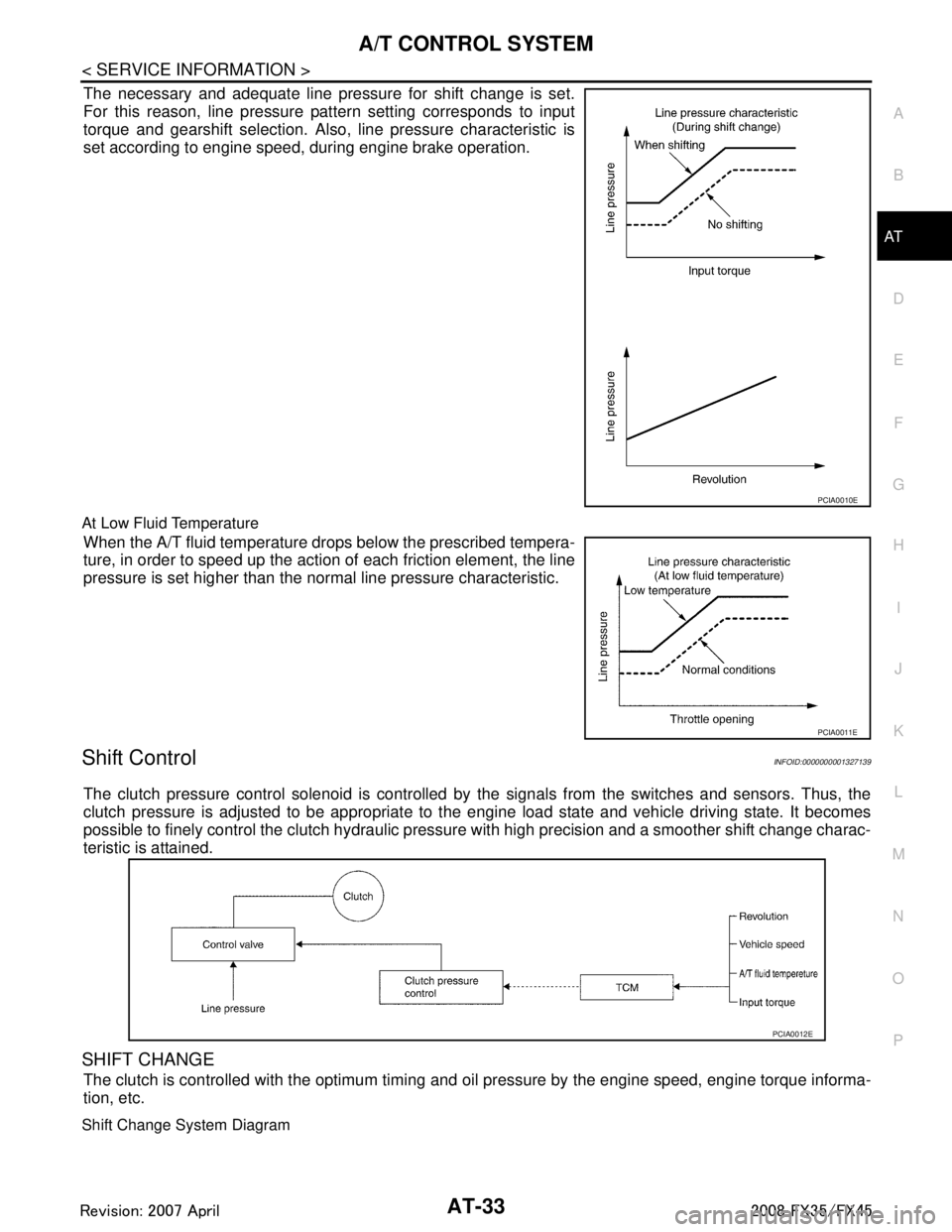
The necessary and adequate line pressure for shift change is set.
For this reason, line pressure pattern setting corresponds to input
torque and gearshift selection. Also, line pressure characteristic is
set according to engine speed, during engine brake operation.
At Low Fluid Temperature
When the A/T fluid temperature drops below the prescribed tempera-
ture, in order to speed up the action of each friction element, the line
pressure is set higher than the normal line pressure characteristic.
Shift ControlINFOID:0000000001327139
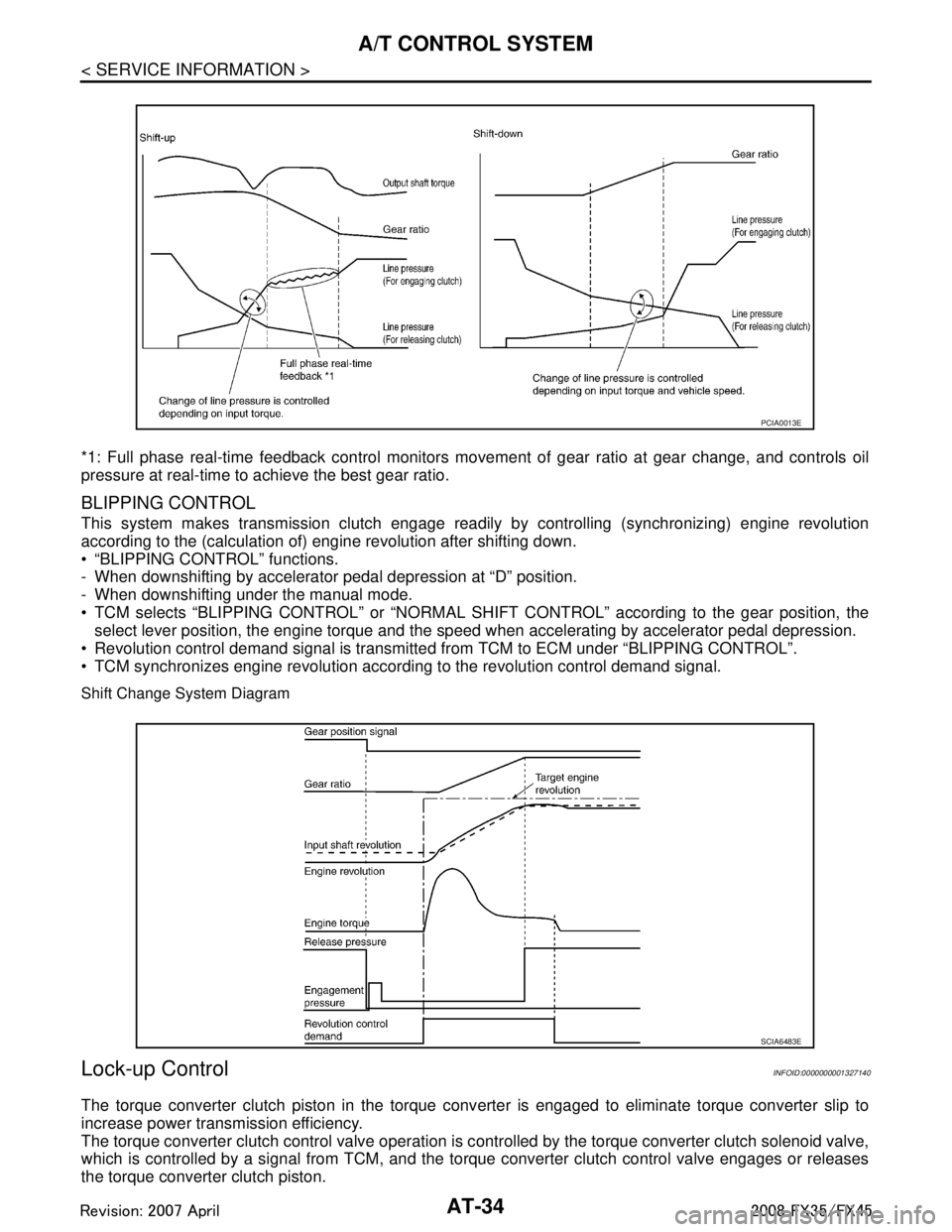
The clutch pressure control solenoid is controlled by the signals from the switches and sensors. Thus, the
clutch pressure is adjusted to be appropriate to t he engine load state and vehicle driving state. It becomes
possible to finely control the clutch hydraulic pressu re with high precision and a smoother shift change charac-
teristic is attained.
SHIFT CHANGE
The clutch is controlled with the optimum timing and oil pressure by the engine speed, engine torque informa-
tion, etc.
Shift Change System Diagram
PCIA0010E
PCIA0011E
PCIA0012E
3AA93ABC3ACD3AC03ACA3AC03AC63AC53A913A773A893A873A873A8E3A773A983AC73AC93AC03AC3
3A893A873A873A8F3A773A9D3AAF3A8A3A8C3A863A9D3AAF3A8B3A8C
Page 107 of 3924

AT-34
< SERVICE INFORMATION >
A/T CONTROL SYSTEM
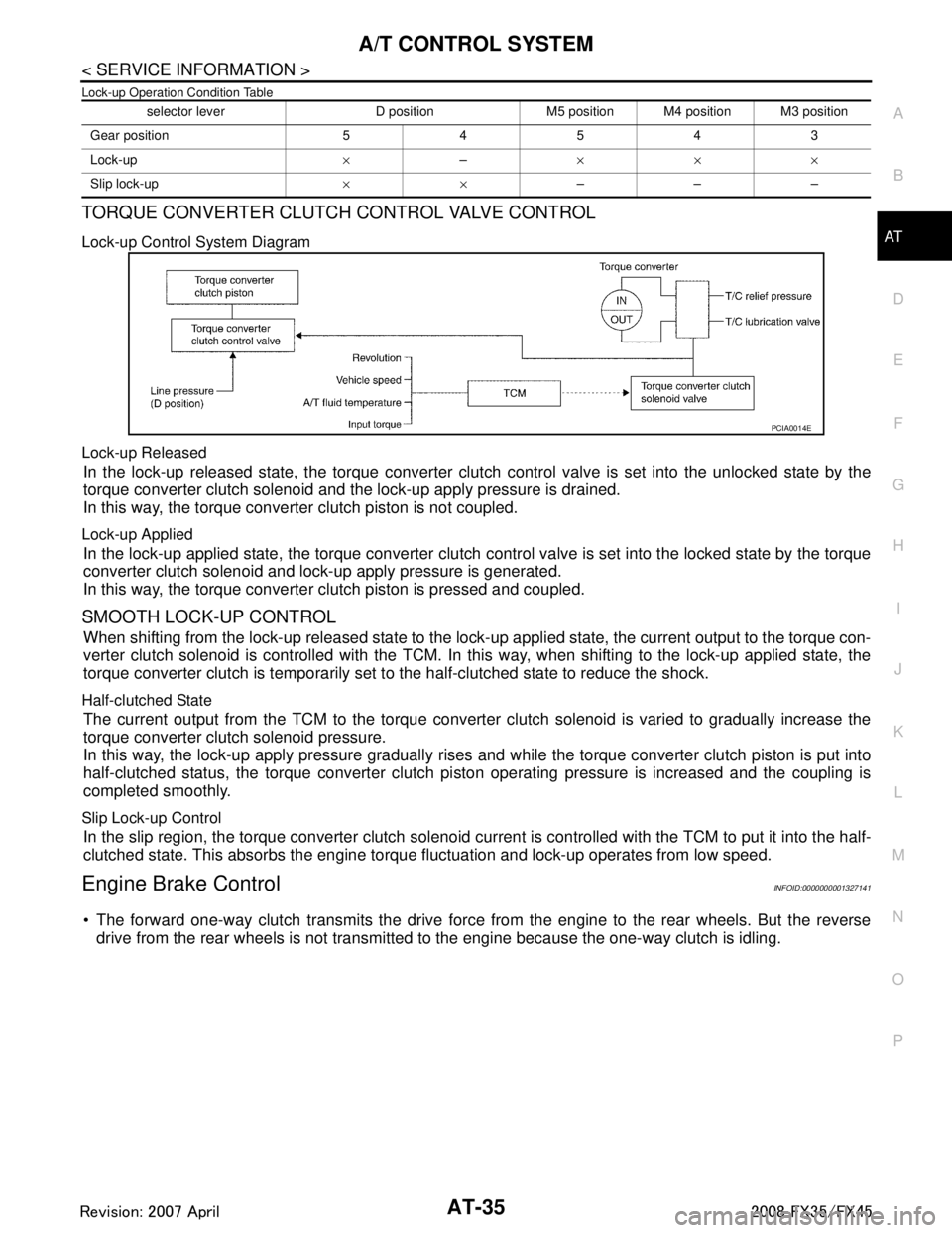
*1: Full phase real-time feedback control monitors movement of gear ratio at gear change, and controls oil
pressure at real-time to achieve the best gear ratio.
BLIPPING CONTROL
This system makes transmission clutch engage readily by controlling (synchronizing) engine revolution
according to the (calculation of) engine revolution after shifting down.
“BLIPPING CONTROL” functions.
- When downshifting by accelerator pedal depression at “D” position.
- When downshifting under the manual mode.
TCM selects “BLIPPING CONTROL” or “NORMAL SHIFT CONTROL” according to the gear position, the
select lever position, the engine torque and the speed when accelerating by accelerator pedal depression.
Revolution control demand signal is transmitted from TCM to ECM under “BLIPPING CONTROL”.
TCM synchronizes engine revolution according to the revolution control demand signal.
Shift Change System Diagram
Lock-up ControlINFOID:0000000001327140
The torque converter clutch piston in the torque conv erter is engaged to eliminate torque converter slip to
increase power transmission efficiency.
The torque converter clutch control valve operation is c ontrolled by the torque converter clutch solenoid valve,
which is controlled by a signal from TCM, and the to rque converter clutch control valve engages or releases
the torque converter clutch piston.
PCIA0013E
SCIA6483E
3AA93ABC3ACD3AC03ACA3AC03AC63AC53A913A773A893A873A873A8E3A773A983AC73AC93AC03AC3
3A893A873A873A8F3A773A9D3AAF3A8A3A8C3A863A9D3AAF3A8B3A8C
Page 108 of 3924

A/T CONTROL SYSTEMAT-35
< SERVICE INFORMATION >
DE
F
G H
I
J
K L
M A
B
AT
N
O P
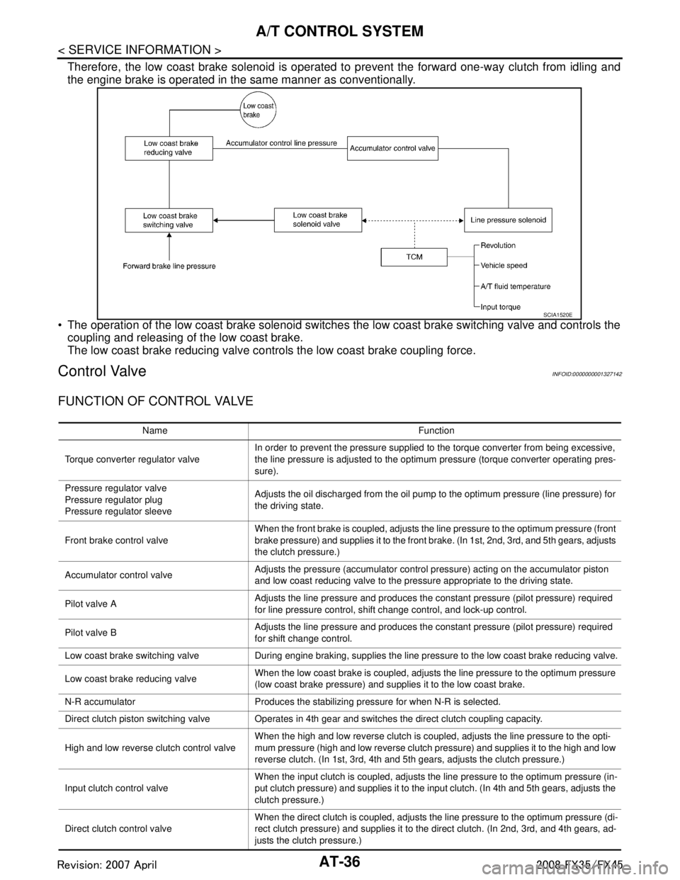
Lock-up Operation Condition Table
TORQUE CONVERTER CLUTCH CONTROL VALVE CONTROL
Lock-up Control System Diagram
Lock-up Released
In the lock-up released state, the torque converter clutch control valve is set into the unlocked state by the
torque converter clutch solenoid and the lock-up apply pressure is drained.
In this way, the torque converter clutch piston is not coupled.
Lock-up Applied
In the lock-up applied state, the torque converter clutch control valve is set into the locked state by the torque
converter clutch solenoid and lock-up apply pressure is generated.
In this way, the torque converter clutch piston is pressed and coupled.
SMOOTH LOCK-UP CONTROL
When shifting from the lock-up released state to the lock- up applied state, the current output to the torque con-
verter clutch solenoid is controlled with the TCM. In this way, when shifting to the lock-up applied state, the
torque converter clutch is temporarily set to the half-clutched state to reduce the shock.
Half-clutched State
The current output from the TCM to the torque converte r clutch solenoid is varied to gradually increase the
torque converter clutch solenoid pressure.
In this way, the lock-up apply pressure gradually rises and while the torque converter clutch piston is put into
half-clutched status, the torque converter clutch pi ston operating pressure is increased and the coupling is
completed smoothly.
Slip Lock-up Control
In the slip region, the torque converter clutch solenoid cu rrent is controlled with the TCM to put it into the half-
clutched state. This absorbs the engine torque fluctuation and lock-up operates from low speed.
Engine Brake ControlINFOID:0000000001327141
The forward one-way clutch transmits the drive force from the engine to the rear wheels. But the reverse
drive from the rear wheels is not transmitted to the engine because the one-way clutch is idling.
selector lever D position M5 position M4 position M3 position
Gear position 54543
Lock-up ×– ×××
Slip lock-up ××–––
PCIA0014E
3AA93ABC3ACD3AC03ACA3AC03AC63AC53A913A773A893A873A873A8E3A773A983AC73AC93AC03AC3
3A893A873A873A8F3A773A9D3AAF3A8A3A8C3A863A9D3AAF3A8B3A8C
Page 109 of 3924

AT-36
< SERVICE INFORMATION >
A/T CONTROL SYSTEM
Therefore, the low coast brake solenoid is operated to prevent the forward one-way clutch from idling and
the engine brake is operated in the same manner as conventionally.
The operation of the low coast brake solenoid switches the low coast brake switching valve and controls the
coupling and releasing of the low coast brake.
The low coast brake reducing valve contro ls the low coast brake coupling force.
Control ValveINFOID:0000000001327142
FUNCTION OF CONTROL VALVE
SCIA1520E
Name Function
Torque converter regulator valve In order to prevent the pressure supplied to the torque converter from being excessive,
the line pressure is adjusted to the optimum pressure (torque converter operating pres-
sure).
Pressure regu lator valve
Pressure regulator plug
Pressure regu lator sleeve Adjusts the oil discharged from the oil pump to the optimum pressure (line pressure) for
the driving state.
Front brake control valve When the front brake is coupled, adjusts the line pressure to the optimum pressure (front
brake pressure) and supplies it to the front brake. (In 1st, 2nd, 3rd, and 5th gears, adjusts
the clutch pressure.)
Accumulator control valve Adjusts the pressure (accumulator control pressure) acting on the accumulator piston
and low coast reducing valve to the pressure appropriate to the driving state.
Pilot valve A Adjusts the line pressure and produces the constant pressure (pilot pressure) required
for line pressure control, shift change control, and lock-up control.
Pilot valve B Adjusts the line pressure and produces the constant pressure (pilot pressure) required
for shift change control.
Low coast brake switching valve During engine braking, supplies the line pressure to the low coast brake reducing valve.
Low coast brake reducing valve When the low coast brake is coupled, adjusts the line pressure to the optimum pressure
(low coast brake pressure) and supplies it to the low coast brake.
N-R accumulator Produces the stabilizing pressure for when N-R is selected.
Direct clutch piston switching valve Operates in 4th ge ar and switches the direct clutch coupling capacity.
High and low reverse clutch control valve When the high and low reverse clutch is coupled, adjusts the line pressure to the opti-
mum pressure (high and low reverse clutch pressure) and supplies it to the high and low
reverse clutch. (In 1st, 3rd, 4th and 5th gears, adjusts the clutch pressure.)
Input clutch control valve When the input clutch is coupled, adjusts the line pressure to the optimum pressure (in-
put clutch pressure) and supplies it to the input clutch. (In 4th and 5th gears, adjusts the
clutch pressure.)
Direct clutch control valve When the direct clutch is coupled, adjusts the line pressure to the optimum pressure (di-
rect clutch pressure) and supplies it to the direct clutch. (In 2nd, 3rd, and 4th gears, ad-
justs the clutch pressure.)
3AA93ABC3ACD3AC03ACA3AC03AC63AC53A913A773A893A873A873A8E3A773A983AC73AC93AC03AC3
3A893A873A873A8F3A773A9D3AAF3A8A3A8C3A863A9D3AAF3A8B3A8C
Page 110 of 3924

A/T CONTROL SYSTEMAT-37
< SERVICE INFORMATION >
DE
F
G H
I
J
K L
M A
B
AT
N
O P
FUNCTION OF ATF PRESSURE SWITCH
TCC control valve
TCC control plug
TCC control sleeve Switches the lock-up to operating or released. Also, by performing the lock-up operation
transiently, lock-up smoothly.
Torque converter lubrication valve Operates during lock-up to switch the torque converter, cooling, and lubrication system
oil passage.
Cool bypass valve Allows excess oil to bypass cooler circuit without being fed into it.
Line pressure relief valve Discharges excess oil from line pressure circuit.
N-D accumulator Produces the stabilizing pressure for when N-D is selected.
Manual valve Sends line pressure to each circuit according to the select position. The circuits to which
the line pressure is not sent drain.
Name Function
Name Function
ATF pressure switch 2 (LC/B) Detects any malfunction in the low coast brake hydraulic pressure. When it detects any
malfunction, it puts the system into fail-safe mode.
3AA93ABC3ACD3AC03ACA3AC03AC63AC53A913A773A893A873A873A8E3A773A983AC73AC93AC03AC3
3A893A873A873A8F3A773A9D3AAF3A8A3A8C3A863A9D3AAF3A8B3A8C
Page 115 of 3924

AT-42
< SERVICE INFORMATION >
TROUBLE DIAGNOSIS
When there is an A/T first gear engine brake judgment malfunction, the low coast brake solenoid is switched
OFF to avoid the engine brake operation.
Line Pressure Solenoid
The solenoid is switched OFF and the line pressure is set to the maximum hydraulic pressure to make driving
possible.
Torque Converter Clutch Solenoid
The solenoid is switched OFF to release the lock-up.
Low Coast Brake Solenoid
When a malfunction (electrical or functional) occurs, in or der to make driving possible, if the solenoid is ON,
the transmission is held in 2nd gear; if the solenoid is OFF, the A/T is held in 4th gear. (Engine brake is not
applied in 1st and 2nd gear.)
Input Clutch Solenoid
If a malfunction (electrical or functi onal) occurs with the solenoid either ON or OFF, the A/T is held in 4th gear
to make driving possible.
Direct Clutch Solenoid
If a malfunction (electrical or functi onal) occurs with the solenoid either ON or OFF, the A/T is held in 4th gear
to make driving possible.
Front Brake Solenoid
If a malfunction (electrical or functi onal) occurs with the solenoid ON, in order to make driving possible, the A/
T is held in 5th gear; if the solenoid is OFF, 4th gear.
High and Low Reverse Clutch Solenoid
If a malfunction (electrical or functi onal) occurs with the solenoid either ON or OFF, the A/T is held in 4th gear
to make driving possible.
Turbine Revolution Sensor 1 or 2
The control is the same as if there were no turbi ne revolution sensors, 5th gear and manual mode are prohib-
ited.
How to Perform Trouble Diagnosis for Quick and Accurate RepairINFOID:0000000001327150
INTRODUCTION
The TCM receives a signal from the vehicle speed sensor , accelerator pedal position sensor (throttle position
sensor) or PNP switch and provides shift cont rol or lock-up control via A/T solenoid valves.
The TCM also communicates with the ECM by means of a signal
sent from sensing elements used with the OBD-related parts of the
A/T system for malfunction-diagnos tic purposes. The TCM is capa-
ble of diagnosing malfunctioning parts while the ECM can store mal-
functions in its memory.
Input and output signals must always be correct and stable in the
operation of the A/T system. The A/T system must be in good oper-
ating condition and be free of valve seizure, solenoid valve malfunc-
tion, etc.
It is much more difficult to diagnose a error that occurs intermittently
rather than continuously. Most inte rmittent errors are caused by poor
electric connections or improper wiring. In this case, careful check-
ing of suspected circuits may help prevent the replacement of good
parts.
A visual check only may not find the cause of the errors. A road test
with CONSULT-III (or GST) or a circuit tester connected should be
performed. Follow the "WORK FLOW".
SAT631IB
SAT632I
3AA93ABC3ACD3AC03ACA3AC03AC63AC53A913A773A893A873A873A8E3A773A983AC73AC93AC03AC3
3A893A873A873A8F3A773A9D3AAF3A8A3A8C3A863A9D3AAF3A8B3A8C
Page 118 of 3924

TROUBLE DIAGNOSISAT-45
< SERVICE INFORMATION >
DE
F
G H
I
J
K L
M A
B
AT
N
O P
Diagnostic Worksheet Chart
Customer name MR/MS Model and Year VIN
Trans. Model Engine Mileage
Malfunction Date Manuf. Date In Service Date
Frequency
❏ Continuous ❏ Intermittent ( times a day)
Symptoms ❏ Vehicle does not move. ( ❏ Any position ❏ Particular position)
❏ No up-shift ( ❏ 1st → 2nd ❏ 2nd → 3rd ❏ 3rd → 4th ❏ 4th → 5th)
❏ No down-shift ( ❏ 5th → 4th ❏ 4th → 3rd ❏ 3rd → 2nd ❏ 2nd → 1st)
❏ Lock-up malfunction
❏ Shift point too high or too low.
❏ Shift shock or slip ( ❏ N → D ❏ Lock-up ❏ Any drive position)
❏ Noise or vibration
❏ No kick down
❏ No pattern select
❏ Others
()
A/T CHECK indicator lamp ❏ Continuously lit ❏ Not lit
Malfunction indicator lamp (MIL) ❏ Continuously lit ❏ Not lit
1 ❏ Read the item on cautions concerning fail-safe and understand the customer's complaint. AT- 4 1
2❏
A/T fluid inspection AT- 4 9❏ Leak (Repair leak location.)
❏ State
❏ Amount
3 ❏
Stall test and line pressure test AT- 4 9
❏ Stall test
❏ Torque converter one-way clutch
❏ Front brake
❏ High and low reverse clutch
❏ Low coast brake
❏ Forward brake
❏ Reverse brake
❏ Forward one-way clutch ❏
1st one-way clutch
❏ 3rd one-way clutch
❏ Engine
❏ Line pressure low
❏ Except for input clutch and direct
clutch, clutches and brakes OK
❏ Line pressure inspection - Suspected part:
3AA93ABC3ACD3AC03ACA3AC03AC63AC53A913A773A893A873A873A8E3A773A983AC73AC93AC03AC3
3A893A873A873A8F3A773A9D3AAF3A8A3A8C3A863A9D3AAF3A8B3A8C