2008 GMC SIERRA light
[x] Cancel search: lightPage 389 of 578

Heavy-DutyTrailer Wiring Harness
Package
For vehicles equipped with heavy duty trailering, the
harness is connected to a bracket on the hitch platform.
The seven-wire harness contains the following trailer
circuits:
Yellow: Left Stop/Turn Signal
Dark Green: Right Stop/Turn Signal
Brown: Taillamps
White: Ground
Light Green: Back-up Lamps
Red: Battery Feed*
Dark Blue: Trailer Brake**The fuses for these two circuits are installed in the
underhood electrical center, but the wires are not
connected. They should be connected by your dealer or
a quali�ed service center. The fuse and wire for the
ITBC is factory installed and connected if the vehicle is
equipped with an ITBC. The fuse for the battery
feed is not required if your vehicle has an auxiliary
battery. If your vehicle does not have an auxiliary
battery, have your dealer or authorized service center
install the required fuse.
If you are charging a remote (non-vehicle) battery, press
the tow/haul mode button located at the end of the
shift lever. This will boost the vehicle system voltage and
properly charge the battery. If the trailer is too light for
tow/haul mode, you can turn on the headlamps as
a second way to boost the vehicle system and charge
the battery.
4-91
Page 390 of 578

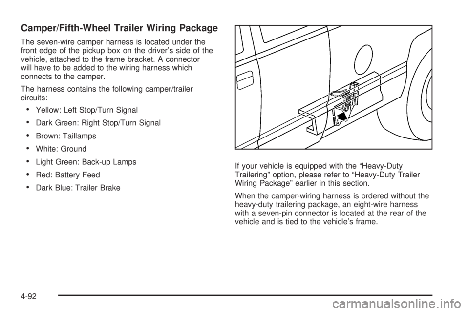
Camper/Fifth-Wheel Trailer Wiring Package
The seven-wire camper harness is located under the
front edge of the pickup box on the driver’s side of the
vehicle, attached to the frame bracket. A connector
will have to be added to the wiring harness which
connects to the camper.
The harness contains the following camper/trailer
circuits:
Yellow: Left Stop/Turn Signal
Dark Green: Right Stop/Turn Signal
Brown: Taillamps
White: Ground
Light Green: Back-up Lamps
Red: Battery Feed
Dark Blue: Trailer BrakeIf your vehicle is equipped with the “Heavy-Duty
Trailering” option, please refer to “Heavy-Duty Trailer
Wiring Package” earlier in this section.
When the camper-wiring harness is ordered without the
heavy-duty trailering package, an eight-wire harness
with a seven-pin connector is located at the rear of the
vehicle and is tied to the vehicle’s frame.
4-92
Page 391 of 578

Electric Brake Control Wiring
Provisions
These wiring provisions are included with your vehicle
as part of the trailer wiring package. These provisions
are for an electric brake controller. The instrument panel
contains blunt cut wires near the data link connector
for the trailer brake controller. The harness contains the
following wires:
Dark Blue: Brake Signal to Trailer Connector
Red/Black: Battery
Light Blue/White: Brake Switch
White: Ground
It should be installed by your dealer or a quali�ed
service center.
If your vehicle is equipped with an ITBC, the blunt cuts
exist, but are not connected further in the harness. If
you install an aftermarket trailer brake controller,
the ITBC must be disconnected. Do not power both
ITBC and aftermarket controllers to control the trailer
brakes at the same time.
Auxiliary Battery
The auxiliary battery provision can be used to supply
electrical power to additional equipment that you
may choose to add, such as a slide-in camper. If your
vehicle has this provision, this relay will be located
on the driver’s side of the vehicle, next to the underhood
electrical center.
Be sure to follow the proper installation instructions that
are included with any electrical equipment that you
install.
Notice:Leaving electrical equipment on for
extended periods will drain the battery. Always turn
off electrical equipment when not in use and do
not use equipment that exceeds the maximum
amperage rating for the auxiliary battery provision.
4-93
Page 403 of 578

To remove the fuel cap, turn it slowly counterclockwise.
{CAUTION:
Fuel can spray out on you if you open the fuel
cap too quickly. If you spill fuel and then
something ignites it, you could be badly
burned. This spray can happen if your tank is
nearly full, and is more likely in hot weather.
Open the fuel cap slowly and wait for any
hiss noise to stop. Then unscrew the cap all
the way.
If your vehicle is a dual fuel tank chassis cab model,
and it runs out of fuel, refuel the front fuel tank �rst to
ensure a quick restart.
Be careful not to spill fuel. Do not top off or over�ll the
tank and wait a few seconds after you have �nished
pumping before removing the nozzle. Clean fuel
from painted surfaces as soon as possible. See
Washing Your Vehicle on page 5-116.
When replacing the fuel cap, turn it clockwise until it
clicks. It will require more effort to turn the fuel cap on
the last turn as you tighten it. Make sure the cap is
fully installed. The diagnostic system can determine ifthe fuel cap has been left off or improperly installed.
This would allow fuel to evaporate into the atmosphere.
SeeMalfunction Indicator Lamp on page 3-48.
The TIGHTEN GAS CAP message will be displayed on
the Driver Information Center (DIC) if the fuel cap is
not properly installed. SeeDIC Warnings and Messages
on page 3-63for more information.
{CAUTION:
If a �re starts while you are refueling, do not
remove the nozzle. Shut off the �ow of fuel by
shutting off the pump or by notifying the
station attendant. Leave the area immediately.
Notice:If you need a new fuel cap, be sure to get
the right type. Your dealer/retailer can get one
for you. If you get the wrong type, it may not �t
properly. This may cause your malfunction indicator
lamp to light and may damage your fuel tank and
emissions system. SeeMalfunction Indicator Lamp
on page 3-48.
5-11
Page 412 of 578

How to Inspect the Engine Air
Cleaner/Filter
Vehicles With an Air Filter Restriction
Indicator
Locate the air �lter restriction indicator on the engine air
cleaner/�lter cover. When the indicator turns black or
is in the red/orange “change” zone, replace the �lter and
reset the indicator. See Steps 1 through 7 to replace
the engine air cleaner/�lter and to reset the air �lter
restriction indicator.
Vehicles Without an Air Filter Restriction
Indicator
To inspect the air cleaner/�lter, remove the engine air
cleaner/�lter from the vehicle by following Steps 1
through 7. When you have the engine air cleaner/�lter
removed, lightly shake it to release loose dust and dirt.
If the engine air cleaner/�lter remains caked with dirt,
a new �lter is required.
Replacing the Engine Air Cleaner/Filter
and Resetting the Air Filter Restriction
Indicator
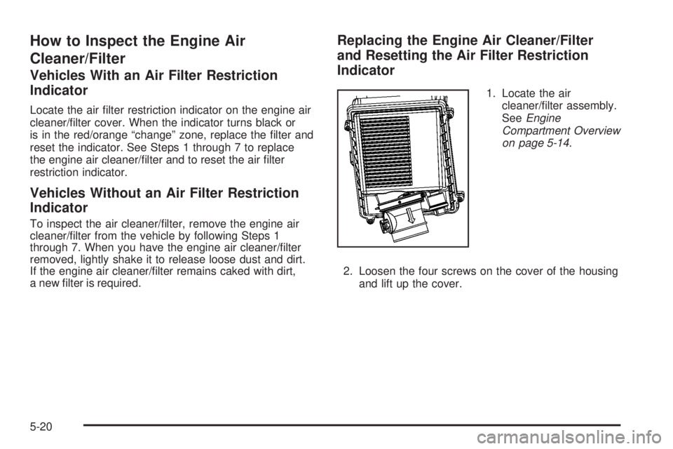
1. Locate the air
cleaner/�lter assembly.
SeeEngine
Compartment Overview
on page 5-14.
2. Loosen the four screws on the cover of the housing
and lift up the cover.
5-20
Page 420 of 578

Engine Coolant
If your vehicle has the DURAMAX®Diesel engine, see
the DURAMAX®Diesel manual for more information.
The cooling system in your vehicle is �lled with
DEX-COOL
®engine coolant. This coolant is designed
to remain in your vehicle for �ve years or 150,000 miles
(240 000 km), whichever occurs �rst, if you add only
DEX-COOL
®extended life coolant.
The following explains your cooling system and how to
add coolant when it is low. If you have a problem
with engine overheating, seeEngine Overheating on
page 5-30.
A 50/50 mixture of clean, drinkable water and
DEX-COOL
®coolant will:
Give freezing protection down to−34°F (−37°C).
Give boiling protection up to 265°F (129°C).
Protect against rust and corrosion.
Help keep the proper engine temperature.
Let the warning lights and gages work as they
should.Notice:Using coolant other than DEX-COOL
®may
cause premature engine, heater core, or radiator
corrosion. In addition, the engine coolant may
require changing sooner, at the �rst maintenance
service after each 30,000 miles (50 000 km) or
24 months, whichever occurs �rst. Any repairs
would not be covered by your warranty. Always use
DEX-COOL
®(silicate-free) coolant in your vehicle.
What to Use
Use a mixture of one-half clean, drinkable water and
one-half DEX-COOL®coolant which will not damage
aluminum parts. If you use this coolant mixture, you do
not need to add anything else.
{CAUTION:
Adding only plain water to your cooling
system can be dangerous. Plain water, or
some other liquid such as alcohol, can boil
before the proper coolant mixture will. Your
vehicle’s coolant warning system is set for the
proper coolant mixture. With plain water or the
wrong mixture, your engine could get too hot
CAUTION: (Continued)
5-28
Page 436 of 578

Brake Wear
Your vehicle has front disc brakes and could have rear
drum brakes or rear disc brakes.
Disc brake pads have built-in wear indicators that make
a high-pitched warning sound when the brake pads
are worn and new pads are needed. The sound can
come and go or be heard all the time your vehicle is
moving, except when you are pushing on the brake
pedal �rmly.
{CAUTION:
The brake wear warning sound means that
soon the brakes will not work well. That could
lead to an accident. When you hear the brake
wear warning sound, have your vehicle
serviced.
Notice:Continuing to drive with worn-out brake
pads could result in costly brake repair.
Some driving conditions or climates can cause a brake
squeal when the brakes are �rst applied or lightly
applied. This does not mean something is wrong with
the brakes.Properly torqued wheel nuts are necessary to help
prevent brake pulsation. When tires are rotated, inspect
brake pads for wear and evenly tighten wheel nuts in
the proper sequence to torque speci�cations in
Capacities and Specifications on page 5-130.
If you have rear drum brakes, they do not have wear
indicators, but if you ever hear a rear brake rubbing
noise, have the rear brake linings inspected immediately.
Rear brake drums should be removed and inspected
each time the tires are removed for rotation or changing.
Drum brakes have an inspection hole to inspect lining
wear during scheduled maintenance. When you have
the front brake pads replaced, have the rear brakes
inspected, too.
Brake linings should always be replaced as complete
axle sets.
Brake Pedal Travel
See your dealer/retailer if the brake pedal does not
return to normal height, or if there is a rapid increase in
pedal travel. This could be a sign that brake service
might be required.
Brake Adjustment
Every time you make a brake stop, the brakes adjust
for wear.
5-44
Page 439 of 578

3. Get the vehicles close enough so the jumper cables
can reach, but be sure the vehicles are not touching
each other. If they are, it could cause an unwanted
ground connection. You would not be able to start
your vehicle, and the bad grounding could damage
the electrical systems.
To avoid the possibility of the vehicles rolling, set
the parking brake �rmly on both vehicles involved in
the jump start procedure. Put the automatic
transmission in PARK (P) or a manual transmission
in NEUTRAL before setting the parking brake.
If you have a four-wheel-drive vehicle, be sure the
transfer case is in a drive gear, not in NEUTRAL.
Notice:If you leave your radio or other accessories
on during the jump starting procedure, they could
be damaged. The repairs would not be covered
by your warranty. Always turn off your radio and
other accessories when jump starting your vehicle.
4. Turn off the ignition on both vehicles. Unplug
unnecessary accessories plugged into the cigarette
lighter or the accessory power outlets. Turn off the
radio and all the lamps that are not needed. This will
avoid sparks and help save both batteries. And it
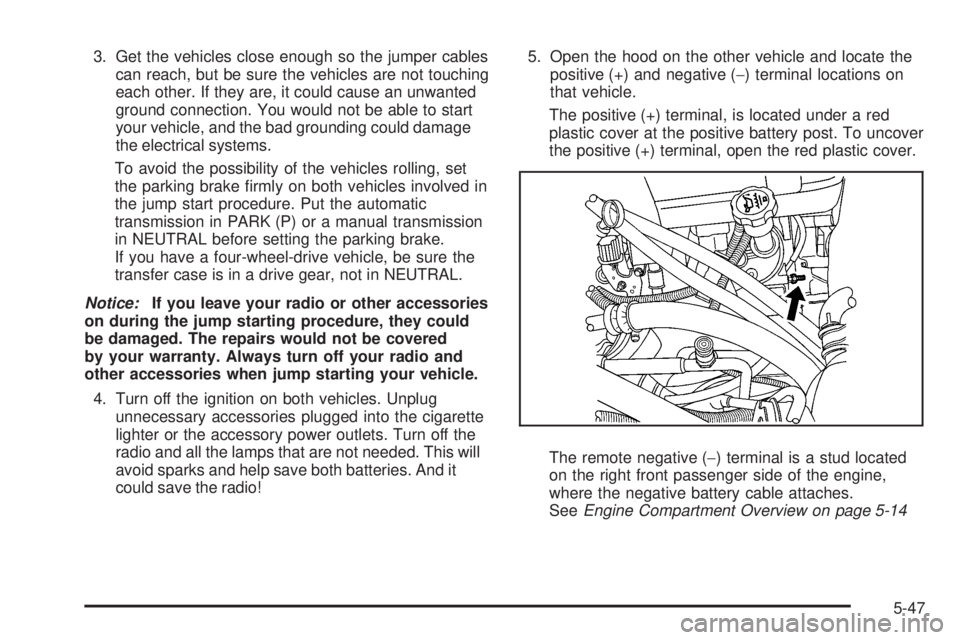
could save the radio!5. Open the hood on the other vehicle and locate the
positive (+) and negative (−) terminal locations on
that vehicle.
The positive (+) terminal, is located under a red
plastic cover at the positive battery post. To uncover
the positive (+) terminal, open the red plastic cover.
The remote negative (−) terminal is a stud located
on the right front passenger side of the engine,
where the negative battery cable attaches.
SeeEngine Compartment Overview on page 5-14
5-47