Page 207 of 416

5-209. Check park warning lamp
(1) Disconnect connector from park switch
(2) Turn ignition switch to ON, park brake warning lamp should go out.
(3) Use conductor to short connector terminal to ground, park brake warning lamp should illuminate.
10. Check park switch
(1) Disconnect connector from park switch
(2) Pull up manual brake, check whether its terminal is connected with ground
Pull up manual brake: on
Manual brake release: off
11. Brake fluid level warning lamp
(1) Disconnect connector from brake fluid level sensor
(2) Turn ignition switch to ON, brake fluid level warning lamp should go out.
(3) Use conductor to connect its connector terminal wiring harness terminals directly, brake fluid level
warning lamp should illuminate.
12. Check brake fluid level warning switch
(1) Remove tank cap
(2) Disconnect connector from tank
(3) Check whether terminals are connected.
Floater on top: off
(4) Use sucker to suck out liquid from tank
(5) Check whether terminals are connected.
Floater down: on state
(6) Pour liquid back into tank
13. Rear defrost indicator lamp
(1) Turn ignition switch to ON, and start up engine
(2) Push down defrost switch, now rear defrost indicator lamp should illuminate
(3) Turn ignition switch to OFF, rear defrost indicator lamp should go out
14. Rear foglight indicator lamp
When rear foglight illuminates, rear foglight indicator lamp should illuminate, now A5 terminal should be high
potential.
15. Safety belt warning indicator lamp
(1) Disconnect safety belt switch connector from driver side, now safety belt warning indicator lamp should
go out.
(2) Short connector terminal to ground, safety belt warning indicator lamp should illuminate.Combination Instrument System -Malfunction Symptom Table and Troubleshooting
Page 229 of 416

Suspected Area
1. Wire between CD box and main unit
2. CD box
3. CD bag
4. CD PLAYER main unit
1. Wire between CD box and main unit
2. CD box
1. CD box
2. CD box installation Symptom
CD can not be taken out
Sound quality poor only when playing CD
(Volume faint)
CD sound jumpTester connection Condition Standard state
GND and vehicle earth Normal status ON
Tester connection Condition Standard state
+B and GND Normal status 10-14V
ACC and GND Ignition switch is in ACC or ON 10-14VII. Trouble shooting1. Power switch system does
not work
Circuit diagram
Abnormal, repair or replace wiring harness, connector
Normal, check and replace radio assembly (1) Check radio assembly (+ B, ACC, GND)
a. As shown in the table below, check connection between terminals in each operating condition.
Standard:
b. As shown in the table below, check voltage between terminals in each operating condition.
Standard:Fuse Box in Engine
CompantmentAudio System -Audio System Inspection5-42MAIN
60AFuse Box under
Instrument Panel
Page 230 of 416
Tester connection Condition Standard state
TAIL and GND Combination switch (light switch) 10-14V2. Turn on light switch, radio backlight
does not illuminate
Circuit diagram
(1) Check radio assembly (TAIL)
As shown in the table below, check voltage between terminals in each operating condition.
Standard:
Abnormal, repair or replace wiring harness, connector
Normal, check and replace radio assembly
3. Loudspeakers is silent in all modes
Circuit diagramAudio System -Audio System Inspection5-43 lamp switch
Please Refer to "MK WIRING DIAGRAM"
Page 253 of 416

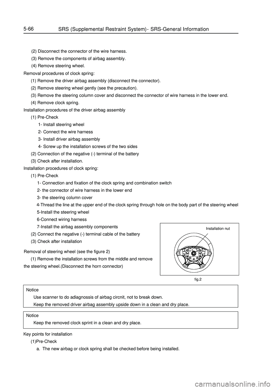
(2) Disconnect the connector of the wire harness.
(3) Remove the components of airbag assembly.
(4) Remove steering wheel.
Removal procedures of clock spring:
(1) Remove the driver airbag assembly (disconnect the connector).
(2) Remove steering wheel gently (see the precaution).
(3) Remove the steering column cover and disconnect the connector of wire harness in the lower end.
(4) Remove clock spring.
Installation procedures of the driver airbag assembly
(1) Pre-Check
1- Install steering wheel
2- Connect the wire harness
3- Install driver airbag assembly
4- Screw up the installation screws of the two sides
(2) Connection of the negative (-) terminal of the battery
(3) Check after installation.
Installation procedures of clock spring:
(1) Pre-Check
1- Connection and fixation of the clock spring and combination switch
2- the connector of wire harness in the lower end
3- the steering column cover
4-Thread the line at the upper end of the clock spring through hole on the body part of the steering wheel
5-Install the steering wheel
6-Connect wiring harness
7-Install the airbag assembly components
(2) Connect the negative (-) terminal cable of the battery
(3) Check after installation5-66Key points for installation
(1)Pre-Check
a. The new airbag or clock spring shall be checked before being installed.SRS (Supplemental Restraint System)-SRS-General InformationNotice
Use scanner to do adiagnossis of airbag circnit, not to break down.
Keep the removed driver airbag assembly upside down in a clean and dry place.Notice
Keep the removed clock sprint in a clean and dry place.fig.2Installation nutRemoval of steering wheel (see the figure 2)
(1) Remove the installation screws from the middle and remove
the steering wheel.(Disconnect the horn connector)
Page 260 of 416

5-73Precautions:1. Don't operate refrigerant in confined space or near open fire.
2. Always wear eyeglass.
3. Be careful don't let liquid refrigerant contact your eyes and skin,
if liquid refrigerant contacts your eye or skin.
(a) Please wash with fresh water.
Warning:
Don't knead your eyes or scrub your skin
(b) Apply soft petroleum ointment on your skin.
(c) See doctor or go to hospital immediately for specialized
treatment.
4. Don't heat container or put it near open fire.
5. Be careful not to fall off, object should not touch container.
6. If there is no sufficient refrigerant in refrigerating system, don't
operate the compressor.
If there is no sufficient refrigerant in the system, insufficient oil
lubrication might cause burning out of compressor. Be careful to
avoid occurrence of such things.
7. When compressor runs, don't turn on pressure gauge high-pressure
valve.
If high-pressure valve is turned on, refrigerant will flow in reverse
direction, and cause bursting of refrigerant tank, so only low
pressure valve may be turned on or off.
8. Be careful to avoid excess refrigerant
Excess refrigerant will result in poor refrigerating capacity, worse
fuel economical efficiency, engine overheat etc problems.Symptom
Blower does not workSymptom table Use the following table to find out the cause of fault, number indicates probable priority of problem, check each
part according to priority, replace components if required.
Suspected Area
1.Blower fuse
2.Centralized controller fuse
3. Blower relay
4. Integrated control panel assembly (blower switch)
5. Blower adjustment resistor
6. Blower
7. Wiring harness.Air Conditioning System -General Information
Page 261 of 416

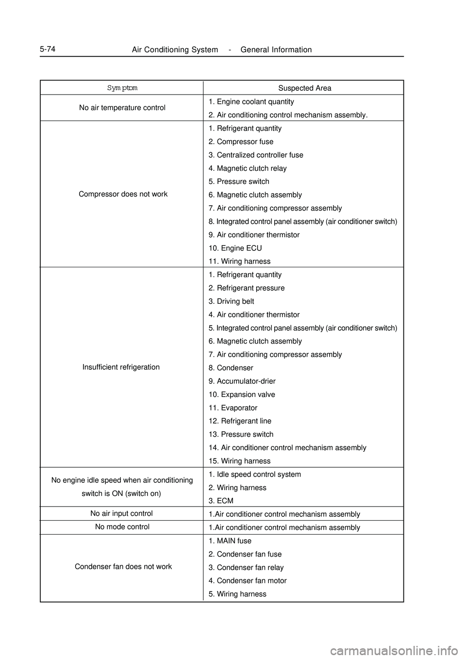
Air Conditioning System -General Information5-74Symptom
No air temperature control
Compressor does not work
Insufficient refrigeration
No engine idle speed when air conditioning
switch is ON (switch on)
No air input control
No mode control
Condenser fan does not workSuspected Area
1. Engine coolant quantity
2. Air conditioning control mechanism assembly.
1. Refrigerant quantity
2. Compressor fuse
3. Centralized controller fuse
4. Magnetic clutch relay
5. Pressure switch
6. Magnetic clutch assembly
7. Air conditioning compressor assembly
8. Integrated control panel assembly (air conditioner switch)
9. Air conditioner thermistor
10. Engine ECU
11. Wiring harness
1. Refrigerant quantity
2. Refrigerant pressure
3. Driving belt
4. Air conditioner thermistor
5. Integrated control panel assembly (air conditioner switch)
6. Magnetic clutch assembly
7. Air conditioning compressor assembly
8. Condenser
9. Accumulator-drier
10. Expansion valve
11. Evaporator
12. Refrigerant line
13. Pressure switch
14. Air conditioner control mechanism assembly
15. Wiring harness
1. Idle speed control system
2. Wiring harness
3. ECM
1.Air conditioner control mechanism assembly
1.Air conditioner control mechanism assembly
1. MAIN fuse
2. Condenser fan fuse
3. Condenser fan relay
4. Condenser fan motor
5. Wiring harness
Page 288 of 416
VIII. Circuit diagramVII. Check list index of fault without fault codeMK-60 ABS system -ABS Diagnosis5-101Fault condition
When Ignition switch is turned to "ON " (engine stall condition), ABS
warning lamp does not illuminate
After Engine is started, warning lamp does not go outCheck list No.
1
2
3
4
5
6Reference page
5-109
5-110
5-111
5-112
5-112
5-113 ABS works
abnormallyBraking force on both sides is not even
Braking force is insufficient
When brake pedal is stepped on slightly, ABS works
(automobile in idle state)
When brake pedal is stepped on slightly, ABS works
(automobile in running state)
When ABS works, brake pedal vibrates excessively
Travel of brake pedal is too long
A very large force is needed to step on brake pedal
No fault code output (cannot communicate with fault diagnosis instrument)Please Refer to "MK WIRING DIAGRAM"
Page 289 of 416
3317
247
1632
17 6 5 4 3 2 1ABS ECU socket pin distribution (wiring harness end)
(1) ABS ECU socket (view of leading-out terminal) (3) Diagnosis connector (2) Trouble light driver module46
31
15MK-60 ABS system -ABS Diagnosis5-102