2008 GEELY MK lock
[x] Cancel search: lockPage 49 of 416

Chapter 2 Engine MechanicalSection 1 Engine ComponentsComponent ViewFigure 2-1Engine MechanicalEngine Components3-8Upside of radiator support
Engine cover lock assembly
Starter assembly
Output pipe of oil cooler
Input pipe of oil coolerTransmission control cable assembly Fuel oil sub-assembly Accelerator control cable assemble
Water inlet pipe of heater
Water outlet pipe of heaterTransmission control cable assemblySuitable for 1.5L/1.6L(Tight coupling)Suitable for 1.3L/1.5L(Non-tight coupling) Radiator assemblyAir filter assembly with hose
Clutch release assembly
Water inlet pipe of radiator
Water outlet pipe of radiator
Battery -
Page 54 of 416

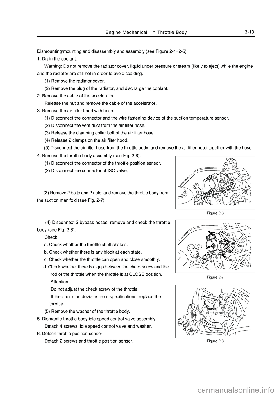
Dismounting/mounting and disassembly and assembly (see Figure 2-1~2-5).
1. Drain the coolant.
Warning: Do not remove the radiator cover, liquid under pressure or steam (likely to eject) while the engine
and the radiator are still hot in order to avoid scalding.
(1) Remove the radiator cover.
(2) Remove the plug of the radiator, and discharge the coolant.
2. Remove the cable of the accelerator.
Release the nut and remove the cable of the accelerator.
3. Remove the air filter hood with hose.
(1) Disconnect the connector and the wire fastening device of the suction temperature sensor.
(2) Disconnect the vent duct from the air filter hose.
(3) Release the clamping collar bolt of the air filter hose.
(4) Release 2 clamps on the air filter hood.
(5) Disconnect the air filter hose from the throttle body, and remove the air filter hood together with the hose.Figure 2-6
Figure 2-7
Figure 2-8Engine MechanicalThrottle Body3-134. Remove the throttle body assembly (see Fig. 2-6).
(1) Disconnect the connector of the throttle position sensor.
(2) Disconnect the connector of ISC valve.
(3) Remove 2 bolts and 2 nuts, and remove the throttle body from
the suction manifold (see Fig. 2-7).
(4) Disconnect 2 bypass hoses, remove and check the throttle
body (see Fig. 2-8).
Check:
a. Check whether the throttle shaft shakes.
b. Check whether there is any block at each state.
c. Check whether the throttle can open and close smoothly.
d. Check whether there is a gap between the check screw and the
rod of the throttle when the throttle is at CLOSE position.
Attention:
Do not adjust the check screw of the throttle.
If the operation deviates from specifications, replace the
throttle.
(5) Remove the washer of the throttle body.
5. Dismantle throttle body idle speed control valve assembly.
Detach 4 screws, idle speed control valve and washer.
6. Detach throttle position sensor
Detach 2 screws and throttle position sensor.Coolant Bypass Pipe -
Page 56 of 416

Chapter 3 Fuel SystemSection 1 Check Fuel System PressureOn-board inspection
1. Check the operation of the fuel pump.
(1) Connect the positive and the negative of the battery to
appropriate connector sockets of the fuel pump (see Figure 3-1).
Attention: Do not start the engine.
If there is pressure present, you will hear that the fuel is flowing.
If there is no pressure present, check the fusible cutout, fuse, EFI
open-circuit relay, fuel pump, ECM (Electronic Control Module) and
circuit joint.
(2) Turn the ignition switch to "OFF".
2. Check the pressure of the fuel.
(1) Check whether the battery voltage is more than 12V.
(2) Disconnect the negative wiring cable from the battery.
(3) Mount a pressure gauge on the fuel input pipe
(see Figure 3-2).
(4) Connect the negative terminal of the battery.
(5) Measure the fuel pressure.
Fuel oil pressure: 265-304kPa
If the pressure is low, check the fuel pipe and connection,
fuel pump, and fuel filter. If the pressure is too high,
replace the regulator.
(6) Start the engine. Measure the fuel pressure at idle speed. The
fuel pressure is 265-304KPa. If the pressure is unsatisfactory, checkFigure 3-1
Figure 3-3 Figure 3-2Fuel SystemCheck Fuel System Pressure3-15the fuel pump, pressure regulator, and injector, and replace if necessary.
(7) After shutting down the engine, check the fuel pressure and
keep the specified pressure for about 5 minutes. The fuel pressure is:
147KPa.
3. The fuel oil pressure regulator (DR) (see Figure 3-3).
Mounting position: On the distributing pipe for fuel.
Faults: Too low or too high fuel pressure, or hard to start.
General causes: Using poor fuel for a long time results in: 1.
strainer blocked; 2. serious leakage caused by particles and impurities.
Other reasons: Man-made mechanical damage, etc.
Maintenance precautions: During maintenance: 1. Never impact the diaphragm element with high pressure
gas; 2. Never clean it with aggressively corrosive liquid; 3. No distortion caused by external force.
Easy measuring method: For the system with oil return, connect a pressure gauge for the fuel on the suction
pipe, start the engine, and run at idle speed. Now, the fuel pressure in the engine should be about 260KPa; pull out
the vacuum pipe of the fuel pressure regulator, and the pressure should be 300KPa approximately.Battery
T conector
Hose
Hose
Fuel Inlet Pipe
Fuel Pipe
Conector -
Page 60 of 416

Section 5 Carbon Canister Replacement1. Check and replace the canister.
(1) Check for crack or damage on the canister visually (see Figure 3-13).
(2) Check the operation of the canister.
a. Plug the discharge port (see Figure 3-14).
b. Blow air (4.71KPa, 48kgf/cm2) into the absorption port when keeping the discharge port closed, and the
air should flow out from the exit port.
If the operation is unsatisfactory, replace the canister.
c.Blow air into the absorption port, the air should flow from other ports without any resistance.
If the operation is unsatisfactory, replace the canister.
(3) Clean the canister: Block the desorption port, blow air (4.71KPa, 48kgf/cm2) into the absorption port, and
the air should flow from the discharge port (see Figure 3-15).Fuel SystemCarbon Canister Replacement3-192. Canister control valve (TEV) (see Figure 3-16)
Mounting position: On the vacuum pipeline of the canister - suction manifold.
Faults: Bad idle speed, malfunction, etc.
General cause: Ingress of foreign materials into inside of the valve results in corrosion and Poor tightness.
Maintenance precautions: During maintenance:
1. Air flowing direction must conform to specifications;
2. If the control valve fails due to black particles in the valve body, and it is necessary to replace the control
valve, please check the condition of the canister;
3. Avoid liquid such as water and oil entering into the valve during maintaining as possible;
4. It is advisable to mount the canister control valve on the hose hanging in the air or fasten with soft rubber
to avoid transmission of solid borne noise.Figure 3-13Figure 3-15 Absorption port
Discharge port
Exit port
Plug upFigure 3-14Absorption port
Discharge port
Exit port -
Page 71 of 416

The valve body fails.
12. The vehicle shifts before or after some gear points in the running status.
The vehicle switch or parking switch fails.
13. The vehicle has poor acceleration in running.
(1)The clutch or brake fails.
(2)The engine system fails.
14. The vehicle vibrates when it runs at a constant speed or accelerating speed.
(1)The hydraulic torque clutch pressure or hydraulic torque meter fails.
(2)The engine system or valve fails.
15. The acceleration switch system fails.
(1)The acceleration switch or ignition switch fails.
(2)The connector or automatic transmission control unit fails.I. Automatic transmissions Removal1. Put the select lever in "N" position
2. Remove 3 bolts of the flexibility plate (engine side)
3. Remove starter and 2 cooling hoses.
4. Disconnect neutral switch connector and odometer sensor.
5. Loosen the drain screw under the housing to bleed ATF and tighten the drain screw with sealing glue when
assembling. Tightening torque is 29~35N.m
6. Loosen the locking bolt for select lever cable.
7. Remove Drive Shaft LH&RH, using plastic stopper in the oil sealing of differential.
8. Detach suspension bolts.
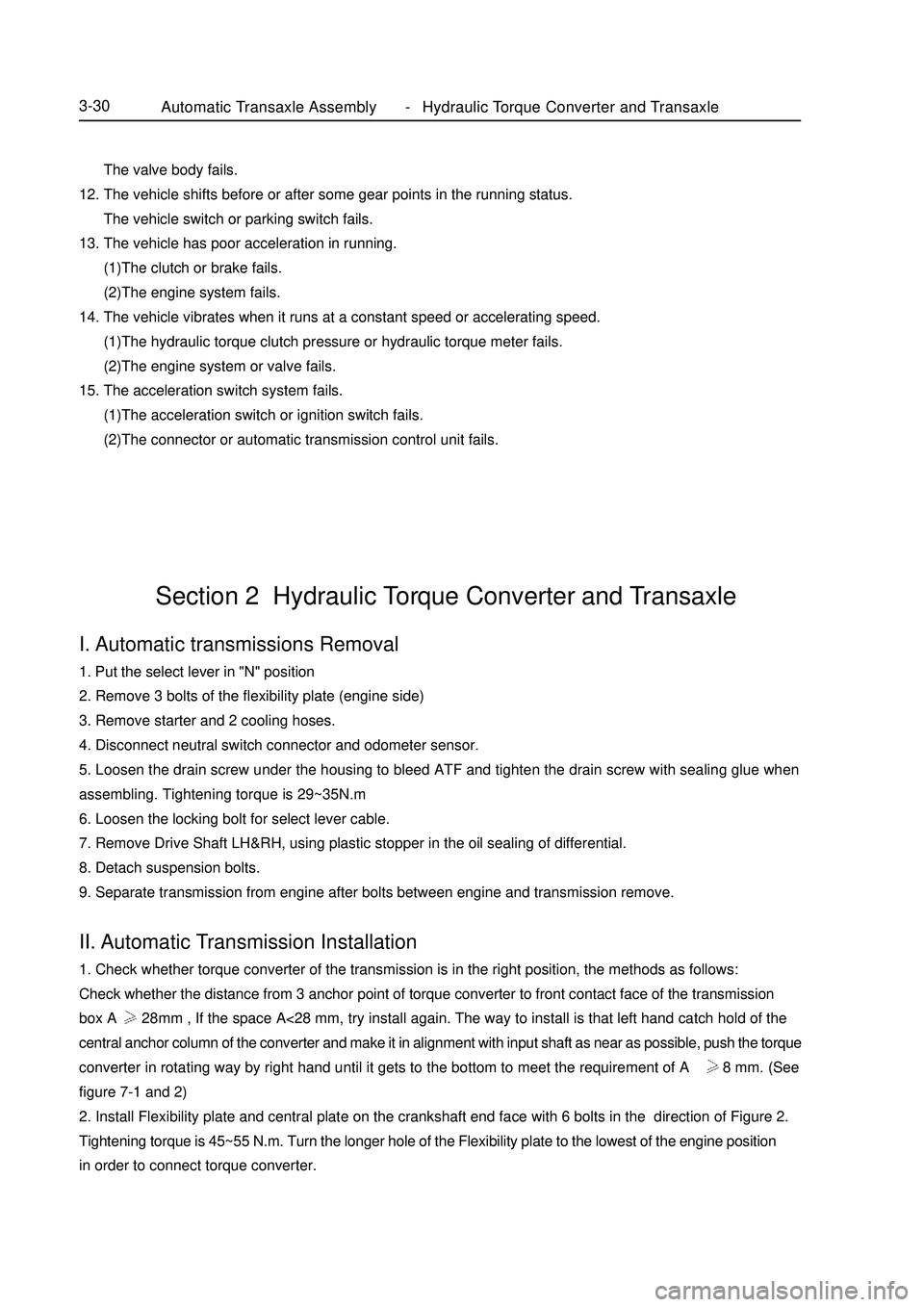
9. Separate transmission from engine after bolts between engine and transmission remove.II. Automatic Transmission Installation1. Check whether torque converter of the transmission is in the right position, the methods as follows:
Check whether the distance from 3 anchor point of torque converter to front contact face of the transmission
box A 28mm , If the space A<28 mm, try install again. The way to install is that left hand catch hold of the
central anchor column of the converter and make it in alignment with input shaft as near as possible, push the torque
converter in rotating way by right hand until it gets to the bottom to meet the requirement of A 28 mm. (See
figure 7-1 and 2)
2. Install Flexibility plate and central plate on the crankshaft end face with 6 bolts in the direction of Figure 2.
Tightening torque is 45~55 N.m. Turn the longer hole of the Flexibility plate to the lowest of the engine position
in order to connect torque converter.Section 2 Hydraulic Torque Converter and TransaxleAutomatic Transaxle Assembly Hydraulic Torque Converter and Transaxle3-30 -
Page 72 of 416

Figure 7-3Automatic Transaxle Assembly Hydraulic Torque Converter and Transaxle3-31Figure 7-5 Figure 7-4Figure 7-1
Figure 7-23. Install transmission in the engine, its way like manual transmission. The torque converter cannot be allowed to
move in axial motion during operating (The dimension of A keeps constant). Install starter in the transmission
housing.
4. Connect Flexibility plate with torque converter, using 3 special bolts. The way is as follows. First, assemble one
bolt in the torque converter by the longer hole of the Flexibility plate, and then rotate engine belt pulley to install
the other bolts, finally use torque spanner to tighten the bolts. Tightening torque is 40~50N.m.
5. Install suspension bolt and drive shaft LH&RH, the assembling way like manual transmission.
6. Connect two cooling pipes as showed in the figure 7-3 with the corresponding pipe of transmission with clip.
7. Connect the cable between bracket of throttle and transmission actuator.
8. Throttle valve cable adjustment as follows:
First, use pliers to clip the hexangular position under throttle valve cable.Turn 60°~90°counterclockwise,
and lift throttle valve cable to make throttle valve cable adjustable move to top position, and then turn back
60°~90° clockwise, meanwhile, make it lock (See figure 7-4). Finally put accelerator pedal to end position.
When throttle valve makes "ka-ka" sound, the distance under the throttle valve should meet B=2~8mm. If not,
try again until the gap B=2~8mm under the throttle valve (see figure 7-5), if gap B=2-8mm, throttle valve cable
adjustment is finished.Central
plateFlexible plate
Torque converter
housing end
Torque
converterFront contact face
Torque converter
anchor point
Central anchor col-
umn -
Page 77 of 416

Automatic Transaxle Assembly Neutral Switch Assembly3-36 (4) Turn the rocker arm to the end counterclockwise and rotate 2
teeth clockwise.
(5) Make the position of neutral switch parallel to the basic
central line of neutral switch with a straight rule.
(6) Keep this position and tighten the bolt.
(7) Tighten the shift rocker arm.
(8) Connect the harness of neutral switch.
5. Install transmission cable
(1) Put shift lever to "P" position, meanwhile, make neutral
switch at "P" position.
(2) Use a new E-shaped clip to fix shift cable on the bracket.
(3) Tighten the nut in the front of shift cable.
Torque: 6.9 ~ 13.7 N.m
6. Check and adjust neutral switch. The display should be clear and
correct.
7. Install the lower engine mud baffle.Neutral Referencline -
Page 85 of 416

Transmission ControlAutomatic Transmission Shift Mechanism4-8Component ViewAutomatic Shifter Panel
Dust-Proof Sliding Plate
Gear Range Display
Shift Lock Release Button
Cap
Bulb
Button Spring
Gear Range Indicator
Wire Harness
Shift Lock Unit
Solenoid
Shift Lock Control ArmShift Lever Sub-AssemblyControl Shaft Key Retaining
Cable Control
Arm Slot Pin Shift Lever SupportHandle Connecting RodShift Lever Button Shift Lever Knob Cover
Spring Automatic Shift Handle
Spring Inner Rod
Precoated Part -