2008 GEELY MK transmission oil
[x] Cancel search: transmission oilPage 41 of 416

2-20 (3) Long time exposure to sun damages interior. So it is better to use covers on upper seat backs, and rear
separation board that are exposed to sun.
8. Maintenance of body exterior
Body exterior is to keep body cleanness and brightness to give the impression of beauty and comfort, and to avoid
rust and abnormal paint peeling off. The key points of body maintenances are:
(1) Wash body using the method below:
a. Wash the dirty things off the body by pressurized water, and then clean the body with
soft cloth of sponge from up to down.
b. Dry body surface with good white cloth. Apply brake pedal several times when driving
after the car is washed to get rid of water in braking system.
c. Do not wipe the body when it is dry. Do not clean paint surface and glass with gasoline,
coal oil, narkosid, strong lye or alcohol.
(2) Cleaning windshield glass
Do not use silicon-bronze radical products. To get better cleaning effects, use special glass cleanser.
(3) Cleaning asphalt on the body
Do not peel the asphalt off from body or bumper, but use special cleanser
(4) Paint
Scratches or slight damages can be fixed with special paint spray. It dries in the air.
(5) Cleaning exterior decoration parts and aluminum parts. Wash with water with soap fluid or cleanser, and wash with clean water. To keep the gloss of painted surface,
wax on the surface after it is dry. (6) Polish and wax the body paint polishing and waxing keeps the body bright and pretty, and protects the paint
as well.
a. Polish in winter. Make sure the vehicle body is absolutely clean and dry before
polishing, polish with fluid or milky wax.
b. Vehicle body must be absolutely dry and clean before waxing. Use waxing tools (soft
table tissue or smooth cotton cloth) to cover the body paint surface evenly with wax.
Check if the vehicle body is covered by wax: spray some water onto the paint surface,
if water drops are formed, that surface is waxed, otherwise, clean the surface and wax
it again. Attention: do not wax under sun, or in cold weather.
Attention
1) When using high pressure washing machine, do not point the washing sprayer to transmission, steering
mechanism and other rubber protection parts, or exterior decoration parts, roof welding lines, heat radiator
or engine compartment.
2) The bottom of vehicle body is made of anti-corrosion material,and has been through anti-corrosion process.
After the vehicle has been running frequently on roads de-frozen with salt for some time, clean engine
compartment and lower part of vehicle body and take some protection actions.Usage and Maintenance of MK Series - Daily Maintenance of MK Sedan
Page 47 of 416

Figure 1-7Figure 1-6
Figure 1-8Engine AssemblyRemoval of the Engine Assembly from the Vehicle3-69. Remove the oil tank assembly of the power steering pump (with power steering).
10. Remove the radiator assembly.
11. Disconnect the harness.
12. Disengage the steering column assembly.
13. Disengage No.2 steering countershaft assembly (see Figure 1-6).
Remove the cover sheet of the steering column on the car body.
14. Remove the exhaust pipe assembly in the front.
15. Remove the nut on the front hub (Parts on the other side are
disassembled in the same way).
16. Disconnect the speed sensor on the front wheel (with ABS).
17. Disengage the ball assembly of the steering tie rod.
18. Disengage the front suspension arm sub-assembly.
19. Disengage the front drive shaft assembly (see Figure 1-7).
20. Disengage the front drive shaft from the hub with a plastic
hammer.
21. Disconnect the shift cable or the tie-rod assembly of the
transmission.
22. Disconnect the clutch wheel cylinder assembly or the clutch
cable (M/T).
23. Remove the engine assembly together with the drive bridge:
(1) Hoist the engine a bit with lifting equipment;
(2) Remove 2 bolts, and disengage the right support of the engine
(see Figure 1-8);
(3) Remove 2 bolts, and disengage the left support of the engine;
(4) Remove one bolt, 3 nuts and disengage the rear support of the
engine;
(5) Remove the engine together with the drive bridge and place
them on the floor;
(6) Lift the body.Mark -
Page 49 of 416

Chapter 2 Engine MechanicalSection 1 Engine ComponentsComponent ViewFigure 2-1Engine MechanicalEngine Components3-8Upside of radiator support
Engine cover lock assembly
Starter assembly
Output pipe of oil cooler
Input pipe of oil coolerTransmission control cable assembly Fuel oil sub-assembly Accelerator control cable assemble
Water inlet pipe of heater
Water outlet pipe of heaterTransmission control cable assemblySuitable for 1.5L/1.6L(Tight coupling)Suitable for 1.3L/1.5L(Non-tight coupling) Radiator assemblyAir filter assembly with hose
Clutch release assembly
Water inlet pipe of radiator
Water outlet pipe of radiator
Battery -
Page 60 of 416

Section 5 Carbon Canister Replacement1. Check and replace the canister.
(1) Check for crack or damage on the canister visually (see Figure 3-13).
(2) Check the operation of the canister.
a. Plug the discharge port (see Figure 3-14).
b. Blow air (4.71KPa, 48kgf/cm2) into the absorption port when keeping the discharge port closed, and the
air should flow out from the exit port.
If the operation is unsatisfactory, replace the canister.
c.Blow air into the absorption port, the air should flow from other ports without any resistance.
If the operation is unsatisfactory, replace the canister.
(3) Clean the canister: Block the desorption port, blow air (4.71KPa, 48kgf/cm2) into the absorption port, and
the air should flow from the discharge port (see Figure 3-15).Fuel SystemCarbon Canister Replacement3-192. Canister control valve (TEV) (see Figure 3-16)
Mounting position: On the vacuum pipeline of the canister - suction manifold.
Faults: Bad idle speed, malfunction, etc.
General cause: Ingress of foreign materials into inside of the valve results in corrosion and Poor tightness.
Maintenance precautions: During maintenance:
1. Air flowing direction must conform to specifications;
2. If the control valve fails due to black particles in the valve body, and it is necessary to replace the control
valve, please check the condition of the canister;
3. Avoid liquid such as water and oil entering into the valve during maintaining as possible;
4. It is advisable to mount the canister control valve on the hose hanging in the air or fasten with soft rubber
to avoid transmission of solid borne noise.Figure 3-13Figure 3-15 Absorption port
Discharge port
Exit port
Plug upFigure 3-14Absorption port
Discharge port
Exit port -
Page 65 of 416

Section 2 Radiator Replacement1. Replace the radiator.
(1) Open the radiator cover.
(2) Open the water drain valve and discharge the coolant.
(3) Disconnect the water inlet pipe of the radiator.
(4) Disconnect the water outlet pipe of the radiator.
(5) Disconnect the input pipe of the oil cooler of the automatic transmission (automatic transmission).
(6) Disconnect the output pipe of the oil cooler of the automatic transmission (automatic transmission).
(7) Remove 4 bolts of the radiator mounting support (see Figure 5-8).Figure 5-8
Figure 5-9Cooling SystemRadiator Replacement3-24 (8)Remove the radiator assembly, remove 4 bolts, and separate
the fan and the fan housing (see Figure 5-9).
(9) Mount the cooling fan assembly.
a. Secure the compensating tank assembly on the cooling fan support with bolts; torque: 16 N.m.
b. Mount the fan and the fan housing with 3 bolts; torque: 7.5N.m.
c. Mount the cooling fan assembly on the radiator assembly with 3 bolts; torque: 16N.m.
d. Connect the overflow pipe on the compensating tank assembly and the radiator assembly, and fasten
with the elastic ring.
e. Mount the radiator assembly in the reverse order of dismounting. -
Page 67 of 416

Table 6-1 Frequent problem diagnosisPossible causes
Transmission or the engine is suspended loosely or damaged;
Axial gap is improper;
Gear or bearing is worn or damaged;
Unsatisfactory transmission oil is used or oil level is low;
Engine idle is incorrect.
The oil seal or the O-ring is damaged.
The control cable is unqualified;
Synchronizer is poorly contacted with gear or worn;
Elasticity of the synchronous spring is insufficient;
Unqualified transmission oil is used.
Fork of the shift gear is worn or lifting spring is broken;
Gap between the synchronizer bush and the sleeve spline is too large;
Gear or bearing is worn or damaged. Sympton
Vibration and noise
Oil leakage of the transmission
Hard to shift
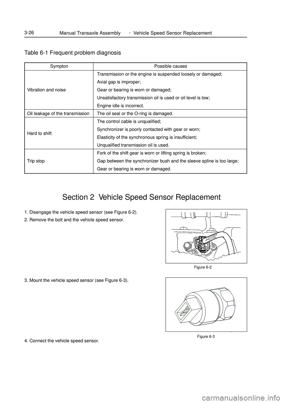
Trip stopManual Transaxle Assembly Vehicle Speed Sensor Replacement3-261. Disengage the vehicle speed sensor (see Figure 6-2).
2. Remove the bolt and the vehicle speed sensor.
3. Mount the vehicle speed sensor (see Figure 6-3).
4. Connect the vehicle speed sensor.Section 2 Vehicle Speed Sensor ReplacementFigure 6-2
Figure 6-3 -
Page 68 of 416

Figure 6-5Manual Transaxle Assembly Manual Transaxle Replacement3-27Section 3 Manual Transaxle ReplacementReplace1. Open the engine cover.
2. Remove the battery.
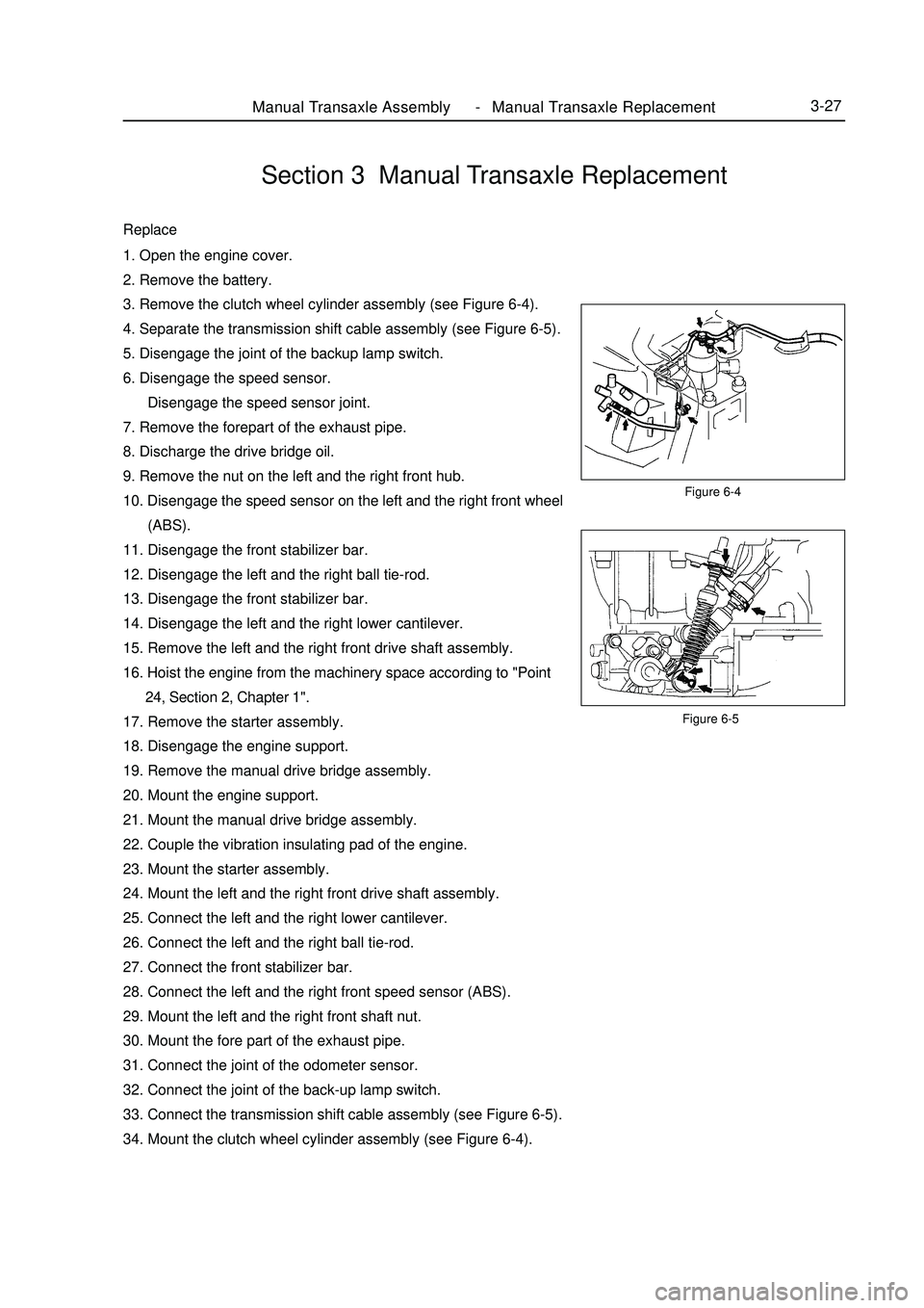
3. Remove the clutch wheel cylinder assembly (see Figure 6-4).
4. Separate the transmission shift cable assembly (see Figure 6-5).
5. Disengage the joint of the backup lamp switch.
6. Disengage the speed sensor.
Disengage the speed sensor joint.
7. Remove the forepart of the exhaust pipe.
8. Discharge the drive bridge oil.
9. Remove the nut on the left and the right front hub.
10. Disengage the speed sensor on the left and the right front wheel
(ABS).
11. Disengage the front stabilizer bar.
12. Disengage the left and the right ball tie-rod.
13. Disengage the front stabilizer bar.
14. Disengage the left and the right lower cantilever.
15. Remove the left and the right front drive shaft assembly.
16. Hoist the engine from the machinery space according to "Point
24, Section 2, Chapter 1".
17. Remove the starter assembly.
18. Disengage the engine support.
19. Remove the manual drive bridge assembly.
20. Mount the engine support.
21. Mount the manual drive bridge assembly.
22. Couple the vibration insulating pad of the engine.
23. Mount the starter assembly.
24. Mount the left and the right front drive shaft assembly.
25. Connect the left and the right lower cantilever.
26. Connect the left and the right ball tie-rod.
27. Connect the front stabilizer bar.
28. Connect the left and the right front speed sensor (ABS).
29. Mount the left and the right front shaft nut.
30. Mount the fore part of the exhaust pipe.
31. Connect the joint of the odometer sensor.
32. Connect the joint of the back-up lamp switch.
33. Connect the transmission shift cable assembly (see Figure 6-5).
34. Mount the clutch wheel cylinder assembly (see Figure 6-4).Figure 6-4 -
Page 69 of 416

I. Replace the oil seal of transmission housing1. Remove the oil seal of the transmission housing (see Figure 6-6).
2. Mount the oil seal of the transmission housing (see Figure 6-7).
Attention:
Take care not to damage the lip surface of the oil seal.II. Replace the Oil Seal of the Drive Bridge Housing1. Remove the oil seal of the transaxle housing with special
maintenance tool (see Figure 6-8).
2. Mount the oil seal of the transaxle housing (see Figure 6-9).Section 4 Transmission/Transaxle Case Oil Seal ReplacementFigure 6-6
Figure 6-7Figure 6-8
Figure 6-9Manual Transaxle Assembly Transmission/Transaxle Case Oil Seal Replacement3-28 -