Page 2 of 368
Locks and Security 136
Keys 136
Locks 136
Anti-theft system 148
Seating and Safety Restraints 151
Seating 151
Safety restraints 158
Airbags 171
Child restraints 180
Tires, Wheels and Loading 192
Tire information 195
Tire inflation 196
Vehicle loading 212
Trailer towing 219
Trailer brake controller-integrated 223
Recreational towing 230
Driving 231
Starting 231
Brakes 235
Traction Control™ 237
Transmission operation 240
Roadside Emergencies 265
Getting roadside assistance 265
Hazard flasher switch 267
Fuel pump shut-off switch 267
Fuses and relays 268
Changing tires 277
Lug nut torque 289
Jump starting 290
Wrecker towing 296
Table of Contents
2
2008 F-250/350/450/550(f23)
Owners Guide (post-2002-fmt)
USA(fus)
Page 97 of 368

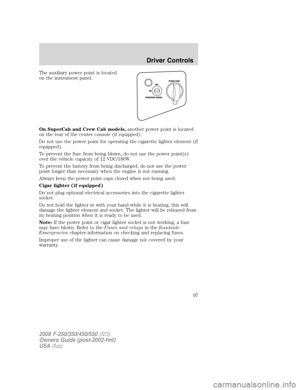
The auxiliary power point is located
on the instrument panel.
On SuperCab and Crew Cab models,another power point is located
on the rear of the center console (if equipped).
Do not use the power point for operating the cigarette lighter element (if
equipped).
To prevent the fuse from being blown, do not use the power point(s)
over the vehicle capacity of 12 VDC/180W.
To prevent the battery from being discharged, do not use the power
point longer than necessary when the engine is not running.
Always keep the power point caps closed when not being used.
Cigar lighter (if equipped)
Do not plug optional electrical accessories into the cigarette lighter
socket.
Do not hold the lighter in with your hand while it is heating, this will
damage the lighter element and socket. The lighter will be released from
its heating position when it is ready to be used.
Note:If the power point or cigar lighter socket is not working, a fuse
may have blown. Refer to theFuses and relaysin theRoadside
Emergencieschapter information on checking and replacing fuses.
Improper use of the lighter can cause damage not covered by your
warranty.
2008 F-250/350/450/550(f23)
Owners Guide (post-2002-fmt)
USA(fus)
Driver Controls
97
Page 109 of 368

Press FAN + or - to adjust fan
speed.
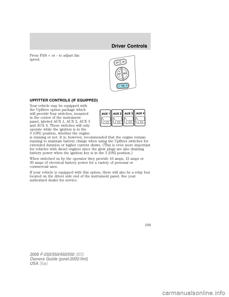
UPFITTER CONTROLS (IF EQUIPPED)
Your vehicle may be equipped with
the Upfitter option package which
will provide four switches, mounted
in the center of the instrument
panel, labeled AUX 1, AUX 2, AUX 3
and AUX 4. These switches will only
operate while the ignition is in the
3 (ON) position, whether the engine
is running or not. It is, however, recommended that the engine remain
running to maintain battery charge when using the Upfitter switches for
extended duration or higher current draws. (This is even more important
for vehicles with diesel engines since the glow plugs are also draining
battery power when the ignition key is in the 3 [ON] position.)
When switched on by the operator they provide 10 amps, 15 amps or
30 amps of electrical battery power for a variety of personal or
commercial uses.
If your vehicle is equipped with this option, there will also be a relay box
located on the driver side end of the instrument panel. See your
authorized dealer for service.
2008 F-250/350/450/550(f23)
Owners Guide (post-2002-fmt)
USA(fus)
Driver Controls
109
Page 110 of 368
The relays are coded as shown in
the accompanying illustration.
There will also be one power lead
for each switch found as a blunt-cut
and sealed wire located below the
instrument panel and to the left of
the steering column.
They are coded as follows:
Switch Circuit number Wire color Fuse
AUX 1 CAC05 Yellow 30A
AUX 2 CAC06 Green with
Brown Trace30A
AUX 3 CAC07 Violet with
Green Trace10A
AUX 4 CAC08 Brown 15A
More detailed information about the Upfitter switches can be found in
theUpfitter Switchesbulletin found at
www.fleet.ford.com/truckbbas/non-html/Q117.pdf.
ONE-TOUCH MOON ROOF (IF EQUIPPED)
The moon roof control is located on the overhead console.
RELAY
1 RELAY
2 RELAY
3 RELAY
4
2008 F-250/350/450/550(f23)
Owners Guide (post-2002-fmt)
USA(fus)
Driver Controls
110
Page 240 of 368

AUTOMATIC TRANSMISSION OPERATION (IF EQUIPPED)
Brake-shift interlock
This vehicle is equipped with a brake-shift interlock feature that prevents
the gearshift lever from being moved from P (Park) when the ignition is
in the 3 (ON) position and the brake pedal is not depressed.
If you cannot move the gearshift lever out of the P (Park) position with
the ignition in the 3 (ON) position and the brake pedal depressed:
1. Apply the parking brake. Turn the
ignition key to 1 (OFF/LOCK), then
remove the key. Locate the access
cover plate for the brake-shift
interlock override. It is located on
top of the steering column shroud.
2. Apply the brake. Use a tool (or a
small screwdriver) to pry out the
access cover. Insert the tool into the
access hole and slide the white
override button towards the left.
Move the gear shift lever into N
(Neutral) while holding the white
override disc towards the left.
When the key is in the ignition and in the OFF position, the
automatic transmission shift lever can be moved from the P
(Park) position without the brake pedal depressed. To avoid unwanted
vehicle movement, always set the parking brake.
3. Start the vehicle.
If it is necessary to use the above procedure to move the gearshift lever,
it is possible that a fuse has blown or the vehicle’s brakelamps are not
operating properly. Refer toFuses and relaysin theRoadside
Emergencieschapter.
Do not drive your vehicle until you verify that the brakelamps
are working.
2008 F-250/350/450/550(f23)
Owners Guide (post-2002-fmt)
USA(fus)
Driving
240
Page 268 of 368
The switch has a red button on top
of it.
To reset the switch:
1. Turn the ignition off.
2. Check the fuel system for leaks.
3. If no leaks are apparent, reset the switch by pushing in on the reset
button.
4. Turn the ignition on.
5. Wait a few seconds and return the key to off.
6. Make another check for leaks.
FUSES AND RELAYS
Fuses
If electrical components in the
vehicle are not working, a fuse may
have blown. Blown fuses are
identified by a broken wire within
the fuse. Check the appropriate
fuses before replacing any electrical
components.
Note:Always replace a fuse with one that has the specified amperage
rating. Using a fuse with a higher amperage rating can cause severe wire
damage and could start a fire.
15
2008 F-250/350/450/550(f23)
Owners Guide (post-2002-fmt)
USA(fus)
Roadside Emergencies
268
Page 271 of 368
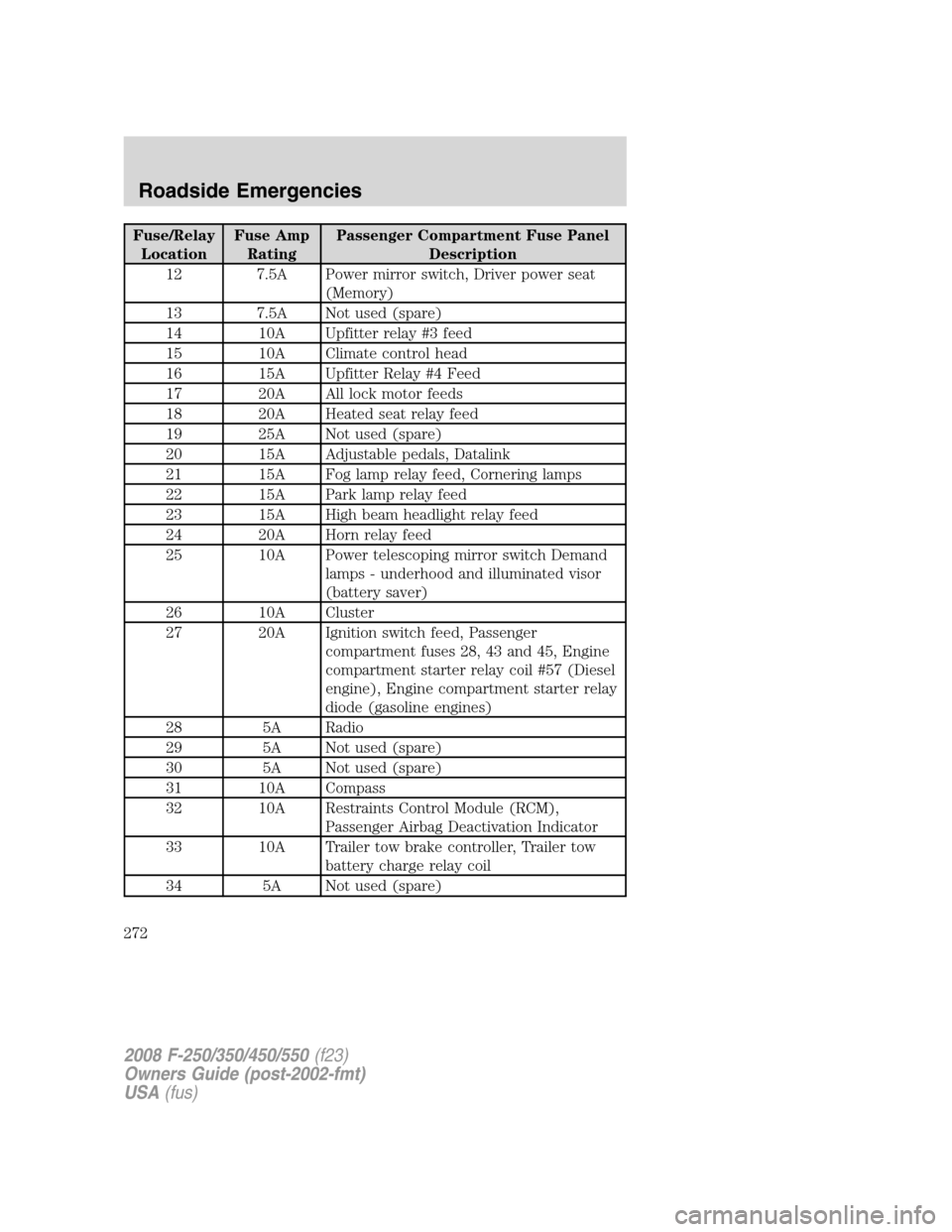
The fuses are coded as follows.
Fuse/Relay
LocationFuse Amp
RatingPassenger Compartment Fuse Panel
Description
1 30A Not used (spare)
2 15A Not used (spare)
3 15A Family Entertainment System (FES)
4 30A Not used (spare)
5 10A Keypad illumination, Brake-Shift Interlock
(BSI)
6 20A Turn signals
7 10A Left headlamp (Low beam)
8 10A Right headlamp (Low beam)
9 15A Interior lighting
10 15A Cargo lamp
11 10A Not used
2008 F-250/350/450/550(f23)
Owners Guide (post-2002-fmt)
USA(fus)
Roadside Emergencies
271
Page 272 of 368

Fuse/Relay
LocationFuse Amp
RatingPassenger Compartment Fuse Panel
Description
12 7.5A Power mirror switch, Driver power seat
(Memory)
13 7.5A Not used (spare)
14 10A Upfitter relay #3 feed
15 10A Climate control head
16 15A Upfitter Relay #4 Feed
17 20A All lock motor feeds
18 20A Heated seat relay feed
19 25A Not used (spare)
20 15A Adjustable pedals, Datalink
21 15A Fog lamp relay feed, Cornering lamps
22 15A Park lamp relay feed
23 15A High beam headlight relay feed
24 20A Horn relay feed
25 10A Power telescoping mirror switch Demand
lamps - underhood and illuminated visor
(battery saver)
26 10A Cluster
27 20A Ignition switch feed, Passenger
compartment fuses 28, 43 and 45, Engine
compartment starter relay coil #57 (Diesel
engine), Engine compartment starter relay
diode (gasoline engines)
28 5A Radio
29 5A Not used (spare)
30 5A Not used (spare)
31 10A Compass
32 10A Restraints Control Module (RCM),
Passenger Airbag Deactivation Indicator
33 10A Trailer tow brake controller, Trailer tow
battery charge relay coil
34 5A Not used (spare)
2008 F-250/350/450/550(f23)
Owners Guide (post-2002-fmt)
USA(fus)
Roadside Emergencies
272