Page 2 of 400
Locks and Security 144
Keys 144
Locks 144
Anti-theft system 155
Seating and Safety Restraints 158
Seating 158
Safety restraints 164
Airbags 183
Child restraints 192
Tires, Wheels and Loading 209
Tire information 211
Tire inflation 213
Tire Pressure Monitoring System (TPMS) 226
Vehicle loading 237
Trailer towing 243
Recreational towing 257
Driving 258
Starting 258
Brakes 264
Traction Control™ 266
Transmission operation 269
Snowplowing 293
Roadside Emergencies 296
Getting roadside assistance 296
Hazard flasher switch 298
Fuel pump shut-off switch 298
Fuses and relays 299
Changing tires 307
Lug nut torque 314
Jump starting 315
Wrecker towing 320
Table of Contents
2
2008 F-150(f12)
Owners Guide (post-2002-fmt)
USA(fus)
Page 140 of 400

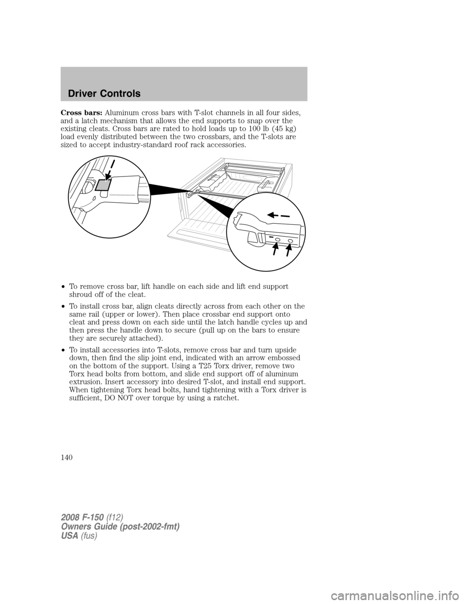
Cross bars:Aluminum cross bars with T-slot channels in all four sides,
and a latch mechanism that allows the end supports to snap over the
existing cleats. Cross bars are rated to hold loads up to 100 lb (45 kg)
load evenly distributed between the two crossbars, and the T-slots are
sized to accept industry-standard roof rack accessories.
•To remove cross bar, lift handle on each side and lift end support
shroud off of the cleat.
•To install cross bar, align cleats directly across from each other on the
same rail (upper or lower). Then place crossbar end support onto
cleat and press down on each side until the latch handle cycles up and
then press the handle down to secure (pull up on the bars to ensure
they are securely attached).
•To install accessories into T-slots, remove cross bar and turn upside
down, then find the slip joint end, indicated with an arrow embossed
on the bottom of the support. Using a T25 Torx driver, remove two
Torx head bolts from bottom, and slide end support off of aluminum
extrusion. Insert accessory into desired T-slot, and install end support.
When tightening Torx head bolts, hand tightening with a Torx driver is
sufficient, DO NOT over torque by using a ratchet.
2008 F-150(f12)
Owners Guide (post-2002-fmt)
USA(fus)
Driver Controls
140
Page 141 of 400

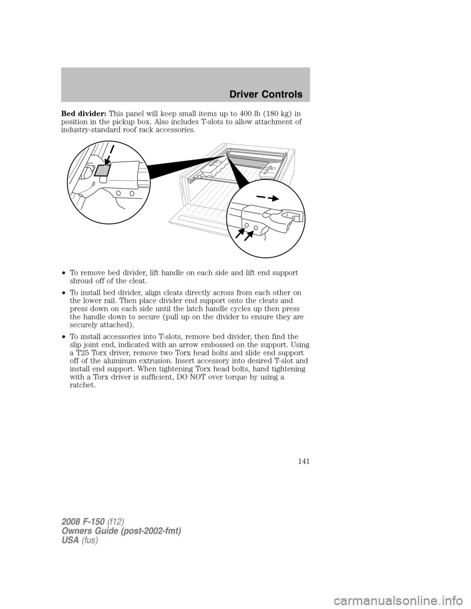
Bed divider:This panel will keep small items up to 400 lb (180 kg) in
position in the pickup box. Also includes T-slots to allow attachment of
industry-standard roof rack accessories.
•To remove bed divider, lift handle on each side and lift end support
shroud off of the cleat.
•To install bed divider, align cleats directly across from each other on
the lower rail. Then place divider end support onto the cleats and
press down on each side until the latch handle cycles up then press
the handle down to secure (pull up on the divider to ensure they are
securely attached).
•To install accessories into T-slots, remove bed divider, then find the
slip joint end, indicated with an arrow embossed on the support. Using
a T25 Torx driver, remove two Torx head bolts and slide end support
off of the aluminum extrusion. Insert accessory into desired T-slot and
install end support. When tightening Torx head bolts, hand tightening
with a Torx driver is sufficient, DO NOT over torque by using a
ratchet.
2008 F-150(f12)
Owners Guide (post-2002-fmt)
USA(fus)
Driver Controls
141
Page 285 of 400

normal and should be no reason for concern. Refer toShifting to/from
4L (4WD Low)for proper operation.
Shifting between 2H (2WD High) and 4H (4WD High)
•Move the 4WD control between 2H and 4H at any forward speed up to
55 mph (88 km/h).
Note:Do not perform this operation if the rear wheels are slipping.
Note:Some noise may be heard as the system shifts or engages; this is
normal.
Shifting to/from 4L (4WD Low)
1. Bring the vehicle to a complete stop
2. Place the transmission in N (Neutral).
3. Move the 4WD control to the desired position.
•If shifting into 4L (4WD Low), wait for the 4X4 LOW light in the
instrument cluster to turnonindicating the shift is complete.
•If shifting out of 4L (4WD Low), wait for the 4X4 LOW light in the
instrument cluster to turnoffindicating the shift is complete.
Note:Some noise may be heard as the system shifts or engages; this is
normal.
Using the all-wheel drive (AWD) system
(if equipped, Harley-Davidson and Limited only)
This system includes an electronically controlled transfer case. The
system is interactive with the road, continually monitoring and adjusting
torque delivery to the front and rear wheels to optimize traction.
AWD (Auto)- Power delivered to all four wheels, as required, for
increased traction. This is appropriate for all on-road driving conditions,
such as dry road surfaces, wet pavement, snow, gravel and shallow sand.
2008 F-150(f12)
Owners Guide (post-2002-fmt)
USA(fus)
Driving
285
Page 312 of 400
•Rear
To lessen the risk of
personal injury, do not put
any part of your body under the
vehicle while changing a tire. Do
not start the engine when your
vehicle is on the jack. The jack is
only meant for changing the tire.
•Never use the front or rear
differential as a jacking point.
8. Remove the lug nuts with the lug wrench.
9. Replace the flat tire with the spare tire, making sure the valve stem is
facing outward. Reinstall the lug nuts until the wheel is snug against the
hub. Do not fully tighten the lug nuts until the wheel has been lowered.
10. Lower the wheel by turning the jack handle counterclockwise.
11. Remove the jack and fully
tighten the lug nuts in the order
shown (Refer toWheel lug nut
torque specificationslater in this
chapter for the proper lug nut
torque specification):
•Six lug nut wheel
2008 F-150(f12)
Owners Guide (post-2002-fmt)
USA(fus)
Roadside Emergencies
312
Page 314 of 400

6. If removed, install the spare tire lock (if equipped) into the bumper
drive tube with the spare tire lock key (if equipped) and jack handle.
WHEEL LUG NUT TORQUE SPECIFICATIONS
Retighten the lug nuts to the specified torque within 100 miles (160 km)
after any wheel disturbance (rotation, flat tire, wheel removal, etc.).
Bolt size Wheel lug nut torque*
lb.ft. N•m
M14 x 2.0 150 200
* Torque specifications are for nut and bolt threads free of dirt and
rust. Use only Ford recommended replacement fasteners.
When a wheel is installed, always remove any corrosion, dirt or
foreign materials present on the mounting surfaces of the wheel
or the surface of the wheel hub, brake drum or brake disc that
contacts the wheel. Ensure that any fasteners that attach the rotor to
the hub are secured so they do not interfere with the mounting
surfaces of the wheel. Installing wheels without correct metal-to-metal
contact at the wheel mounting surfaces can cause the wheel nuts to
loosen and the wheel to come off while the vehicle is in motion,
resulting in loss of control.
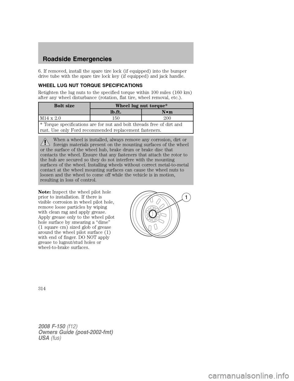
Note:Inspect the wheel pilot hole
prior to installation. If there is
visible corrosion in wheel pilot hole,
remove loose particles by wiping
with clean rag and apply grease.
Apply grease only to the wheel pilot
hole surface by smearing a “dime”
(1 square cm) sized glob of grease
around the wheel pilot surface (1)
with end of finger. DO NOT apply
grease to lugnut/stud holes or
wheel-to-brake surfaces.
2008 F-150(f12)
Owners Guide (post-2002-fmt)
USA(fus)
Roadside Emergencies
314