2008 FORD CROWN VICTORIA battery
[x] Cancel search: batteryPage 91 of 280
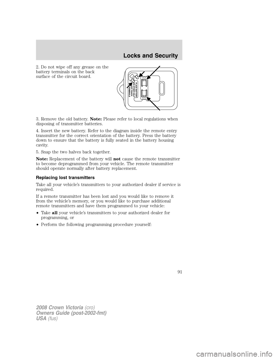
2. Do not wipe off any grease on the
battery terminals on the back
surface of the circuit board.
3. Remove the old battery.Note:Please refer to local regulations when
disposing of transmitter batteries.
4. Insert the new battery. Refer to the diagram inside the remote entry
transmitter for the correct orientation of the battery. Press the battery
down to ensure that the battery is fully seated in the battery housing
cavity.
5. Snap the two halves back together.
Note:Replacement of the battery willnotcause the remote transmitter
to become deprogrammed from your vehicle. The remote transmitter
should operate normally after battery replacement.
Replacing lost transmitters
Take all your vehicle’s transmitters to your authorized dealer if service is
required.
If a remote transmitter has been lost and you would like to remove it
from the vehicle’s memory, or you would like to purchase additional
remote transmitters and have them programmed to your vehicle:
•Takeallyour vehicle’s transmitters to your authorized dealer for
programming, or
•Perform the following programming procedure yourself:
2008 Crown Victoria(cro)
Owners Guide (post-2002-fmt)
USA(fus)
Locks and Security
91
Page 92 of 280
Note:Ensure the brake pedal is not
depressed during this sequence.
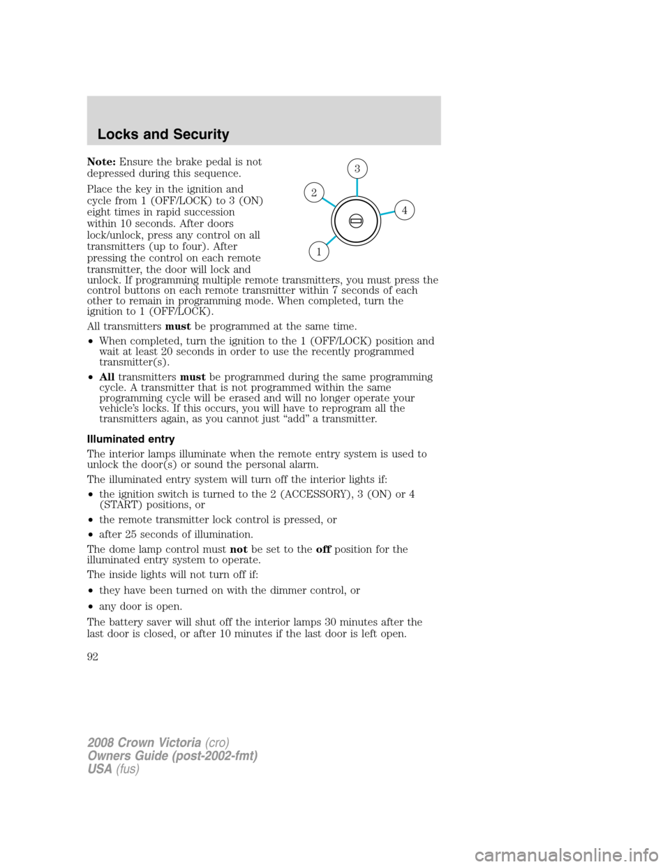
Place the key in the ignition and
cycle from 1 (OFF/LOCK) to 3 (ON)
eight times in rapid succession
within 10 seconds. After doors
lock/unlock, press any control on all
transmitters (up to four). After
pressing the control on each remote
transmitter, the door will lock and
unlock. If programming multiple remote transmitters, you must press the
control buttons on each remote transmitter within 7 seconds of each
other to remain in programming mode. When completed, turn the
ignition to 1 (OFF/LOCK).
All transmittersmustbe programmed at the same time.
•When completed, turn the ignition to the 1 (OFF/LOCK) position and
wait at least 20 seconds in order to use the recently programmed
transmitter(s).
•Alltransmittersmustbe programmed during the same programming
cycle. A transmitter that is not programmed within the same
programming cycle will be erased and will no longer operate your
vehicle’s locks. If this occurs, you will have to reprogram all the
transmitters again, as you cannot just “add” a transmitter.
Illuminated entry
The interior lamps illuminate when the remote entry system is used to
unlock the door(s) or sound the personal alarm.
The illuminated entry system will turn off the interior lights if:
•the ignition switch is turned to the 2 (ACCESSORY), 3 (ON) or 4
(START) positions, or
•the remote transmitter lock control is pressed, or
•after 25 seconds of illumination.
The dome lamp control mustnotbe set to theoffposition for the
illuminated entry system to operate.
The inside lights will not turn off if:
•they have been turned on with the dimmer control, or
•any door is open.
The battery saver will shut off the interior lamps 30 minutes after the
last door is closed, or after 10 minutes if the last door is left open.
4
3
2
1
2008 Crown Victoria(cro)
Owners Guide (post-2002-fmt)
USA(fus)
Locks and Security
92
Page 192 of 280
ROADSIDE ASSISTANCE
Getting roadside assistance
To fully assist you should you have a vehicle concern, Ford Motor Company
offers a complimentary roadside assistance program. This program is
separate from the New Vehicle Limited Warranty. The service is available:
•24–hours, seven days a week
•for the coverage period listed on the Roadside Assistance Card
included in your Owner Guide portfolio.
Roadside assistance will cover:
•a flat tire change with a good spare (except vehicles that have been
supplied with a tire inflation kit)
•battery jump start
•
lock-out assistance (key replacement cost is the customer’s responsibility)
•fuel delivery – Independent Service Contractors, if not prohibited by
state, local or municipal law shall deliver up to 2.0 gallons (7.5L) of
gasoline or 5 gallons (18.9L) of diesel fuel to a disabled vehicle. Fuel
delivery service is limited to two no-charge occurrences within a
12-month period.
•winch out – available within 100 feet (30.5 meters) of a paved or
county maintained road, no recoveries.
•towing – Ford/Mercury/Lincoln eligible vehicle towed to an authorized
dealer within 35 miles (56.3 km) of the disablement location or to the
nearest authorized dealer. If a member requests to be towed to an
authorized dealer more than 35 miles (56.3 km) from the disablement
location, the member shall be responsible for any mileage costs in
excess of 35 miles (56.3 km).
Trailers shall be covered up to $200 if the disabled eligible vehicle
requires service at the nearest authorized dealer. If the trailer is disabled,
but the towing vehicle is operational, the trailer does not qualify for any
roadside services.
Canadian customers refer to your Customer Information Guide
for information on:
•coverage period
•exact fuel amounts
•towing of your disabled vehicle
•emergency travel expense reimbursement
•travel planning benefits
2008 Crown Victoria(cro)
Owners Guide (post-2002-fmt)
USA(fus)
Roadside Emergencies
192
Page 199 of 280
Fuse/Relay
LocationFuse Amp
RatingPassenger Compartment Fuse
Panel Description
24 10A Ignition (ON/START) - Passive
Anti-Theft System (PATS)
module, Powertrain Control
Module (PCM) relay coil, Fuel
relay coil, Ignition coil relay coil
25 15A LCM (Park lamps, license lamps)
26 10A Ignition (ON/START) - Cluster,
LCM, Overdrive cancel switch
27 — Not used
28 7.5A Brake signal, LCM (BTSI), ABS
29 2A Hazard in (Police vehicles only)
30 2A Battery saver (Police vehicles
only)
31 5A Key in (LCM)
32 2A Hazard out (Police vehicles only)
33 10A Ignition (ON/START), Fire
suppression module (if equipped)
(Police vehicles only)
Relay 1 Full ISO relay Window relay, Decklid (Police
vehicles only)
Power distribution box
The power distribution box is located in the engine compartment. The
power distribution box contains high-current fuses that protect your
vehicle’s main electrical systems from overloads.
Always disconnect the battery before servicing high current
fuses.
To reduce risk of electrical shock, always replace the cover to
the Power Distribution Box before reconnecting the battery or
refilling fluid reservoirs.
If the battery has been disconnected and reconnected, refer to the
Batterysection of theMaintenance and Specificationschapter.
2008 Crown Victoria(cro)
Owners Guide (post-2002-fmt)
USA(fus)
Roadside Emergencies
199
Page 201 of 280
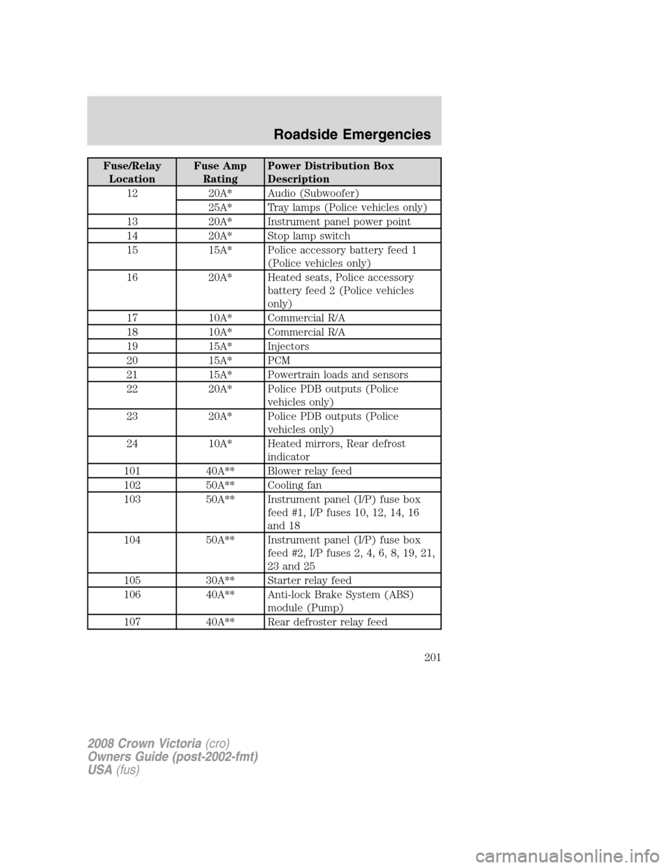
Fuse/Relay
LocationFuse Amp
RatingPower Distribution Box
Description
12 20A* Audio (Subwoofer)
25A* Tray lamps (Police vehicles only)
13 20A* Instrument panel power point
14 20A* Stop lamp switch
15 15A* Police accessory battery feed 1
(Police vehicles only)
16 20A* Heated seats, Police accessory
battery feed 2 (Police vehicles
only)
17 10A* Commercial R/A
18 10A* Commercial R/A
19 15A* Injectors
20 15A* PCM
21 15A* Powertrain loads and sensors
22 20A* Police PDB outputs (Police
vehicles only)
23 20A* Police PDB outputs (Police
vehicles only)
24 10A* Heated mirrors, Rear defrost
indicator
101 40A** Blower relay feed
102 50A** Cooling fan
103 50A** Instrument panel (I/P) fuse box
feed #1, I/P fuses 10, 12, 14, 16
and 18
104 50A** Instrument panel (I/P) fuse box
feed #2, I/P fuses 2, 4, 6, 8, 19, 21,
23 and 25
105 30A** Starter relay feed
106 40A** Anti-lock Brake System (ABS)
module (Pump)
107 40A** Rear defroster relay feed
2008 Crown Victoria(cro)
Owners Guide (post-2002-fmt)
USA(fus)
Roadside Emergencies
201
Page 202 of 280
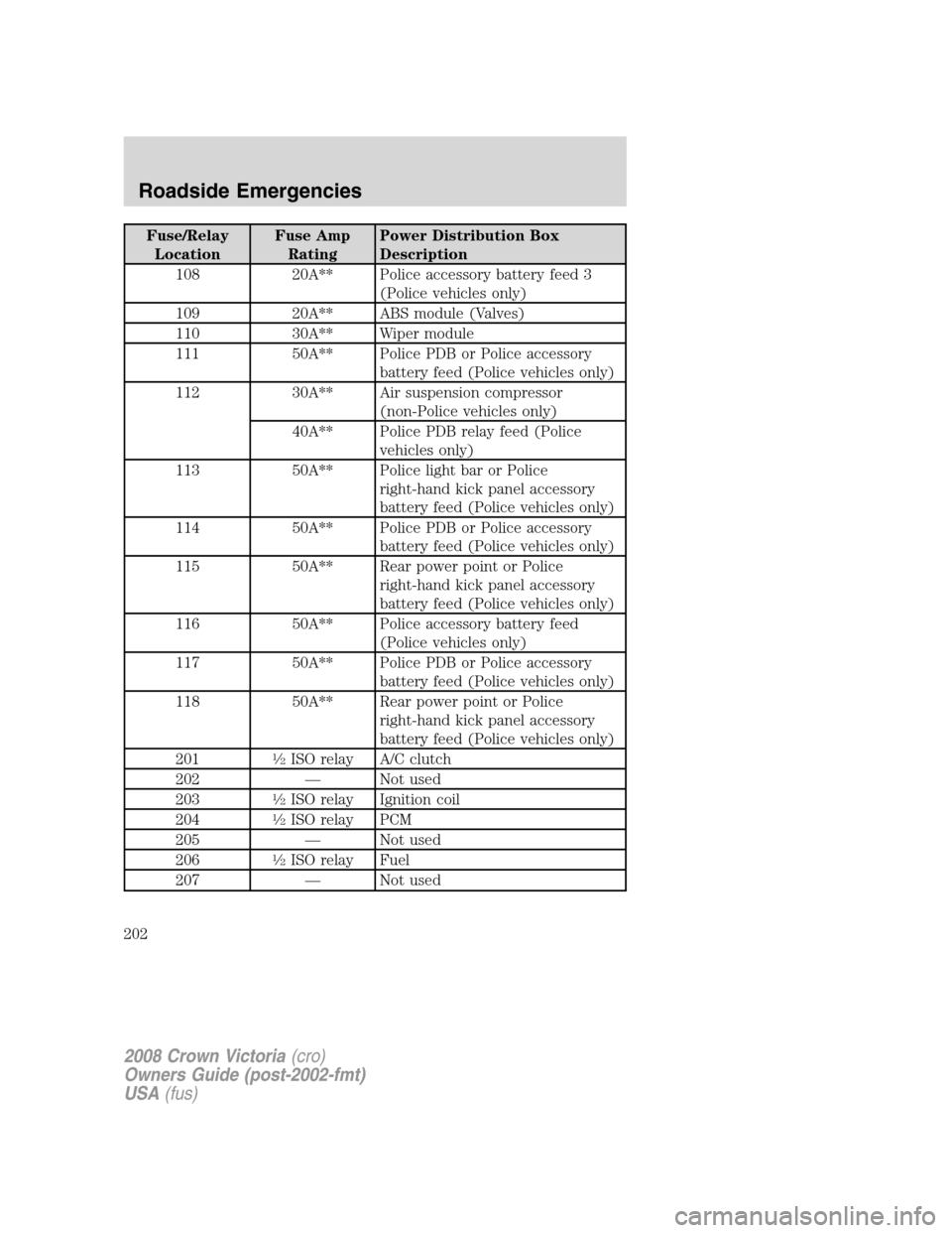
Fuse/Relay
LocationFuse Amp
RatingPower Distribution Box
Description
108 20A** Police accessory battery feed 3
(Police vehicles only)
109 20A** ABS module (Valves)
110 30A** Wiper module
111 50A** Police PDB or Police accessory
battery feed (Police vehicles only)
112 30A** Air suspension compressor
(non-Police vehicles only)
40A** Police PDB relay feed (Police
vehicles only)
113 50A** Police light bar or Police
right-hand kick panel accessory
battery feed (Police vehicles only)
114 50A** Police PDB or Police accessory
battery feed (Police vehicles only)
115 50A** Rear power point or Police
right-hand kick panel accessory
battery feed (Police vehicles only)
116 50A** Police accessory battery feed
(Police vehicles only)
117 50A** Police PDB or Police accessory
battery feed (Police vehicles only)
118 50A** Rear power point or Police
right-hand kick panel accessory
battery feed (Police vehicles only)
201
1�2ISO relay A/C clutch
202 — Not used
203
1�2ISO relay Ignition coil
204
1�2ISO relay PCM
205 — Not used
206
1�2ISO relay Fuel
207 — Not used
2008 Crown Victoria(cro)
Owners Guide (post-2002-fmt)
USA(fus)
Roadside Emergencies
202
Page 211 of 280
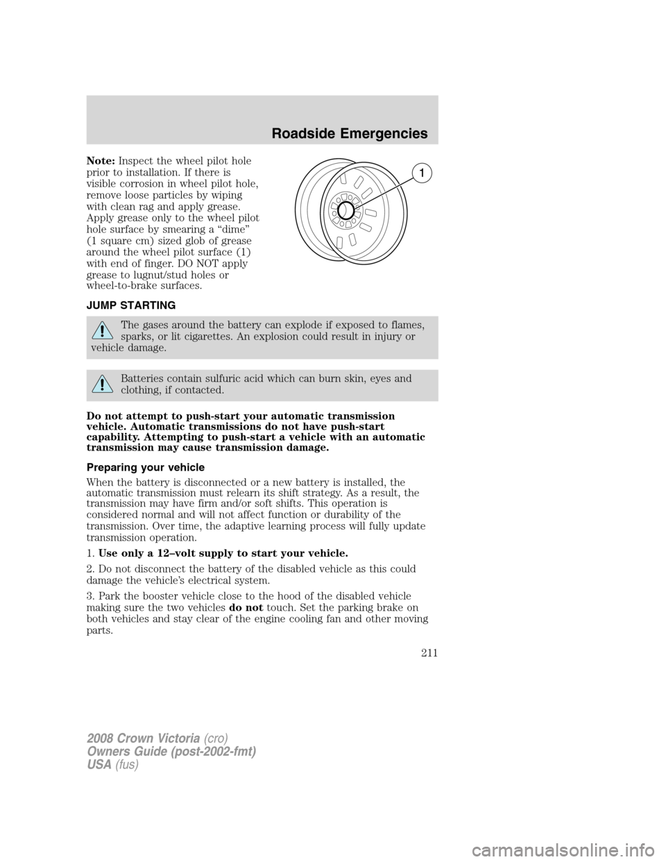
Note:Inspect the wheel pilot hole
prior to installation. If there is
visible corrosion in wheel pilot hole,
remove loose particles by wiping
with clean rag and apply grease.
Apply grease only to the wheel pilot
hole surface by smearing a “dime”
(1 square cm) sized glob of grease
around the wheel pilot surface (1)
with end of finger. DO NOT apply
grease to lugnut/stud holes or
wheel-to-brake surfaces.
JUMP STARTING
The gases around the battery can explode if exposed to flames,
sparks, or lit cigarettes. An explosion could result in injury or
vehicle damage.
Batteries contain sulfuric acid which can burn skin, eyes and
clothing, if contacted.
Do not attempt to push-start your automatic transmission
vehicle. Automatic transmissions do not have push-start
capability. Attempting to push-start a vehicle with an automatic
transmission may cause transmission damage.
Preparing your vehicle
When the battery is disconnected or a new battery is installed, the
automatic transmission must relearn its shift strategy. As a result, the
transmission may have firm and/or soft shifts. This operation is
considered normal and will not affect function or durability of the
transmission. Over time, the adaptive learning process will fully update
transmission operation.
1.Use only a 12–volt supply to start your vehicle.
2. Do not disconnect the battery of the disabled vehicle as this could
damage the vehicle’s electrical system.
3. Park the booster vehicle close to the hood of the disabled vehicle
making sure the two vehiclesdo nottouch. Set the parking brake on
both vehicles and stay clear of the engine cooling fan and other moving
parts.
2008 Crown Victoria(cro)
Owners Guide (post-2002-fmt)
USA(fus)
Roadside Emergencies
211
Page 212 of 280
4. Check all battery terminals and remove any excessive corrosion before
you attach the battery cables. Ensure that vent caps are tight and level.
5. Turn the heater fan on in both vehicles to protect from any electrical
surges. Turn all other accessories off.
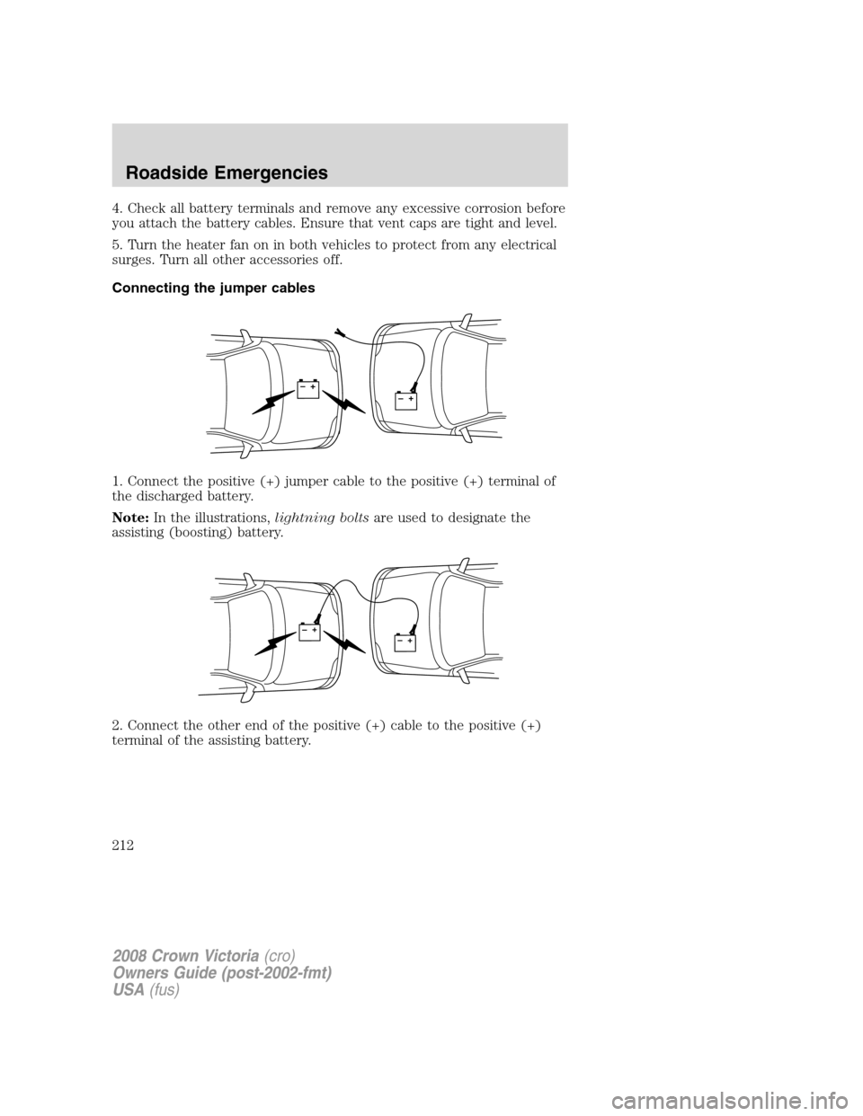
Connecting the jumper cables
1. Connect the positive (+) jumper cable to the positive (+) terminal of
the discharged battery.
Note:In the illustrations,lightning boltsare used to designate the
assisting (boosting) battery.
2. Connect the other end of the positive (+) cable to the positive (+)
terminal of the assisting battery.
+–+–
+–+–
2008 Crown Victoria(cro)
Owners Guide (post-2002-fmt)
USA(fus)
Roadside Emergencies
212