Page 271 of 554

Window Fogging
Windows will fog on the inside when the humidity inside
the vehicle is high. This often occurs in mild or cool
temperatures when it's rainy or humid. In most cases
turning on the air conditioning (pressing the snowflake
button) will clear the fog. Adjust the temperature control,
air direction and blower speed to maintain comfort.
As the temperature gets colder it may be necessary to
direct air onto the windshield by using MIX Mode
position on the control. Adjust the temperature control
and blower speed to maintain comfort. Higher blower
speeds will reduce fogging. Interior fogging on the
windshield can be quickly removed by selecting the
defrost mode.
Regular cleaning of the inside of the windows with a
non-filming cleaning solution (vinegar and water works
very well) will help prevent contaminates (cigarettesmoke, perfumes, etc.) from sticking to the windows.
Contaminates increase the rate of window fogging.
Summer Operation
Air conditioned vehicles must be protected with a high
quality antifreeze coolant during summer to provide
proper corrosion protection and to raise the boiling point
of the coolant for protection against overheating. A 50 %
concentration is recommended. For proper coolant type,
refer to ªRecommended Fluids and Genuine Partsº in
Section 7.
When using the air conditioner in extremely heavy traffic
in hot weather, especially when towing a trailer, addi-
tional engine cooling may be required. If this situation is
encountered, operate the transmission in a lower gear to
increase engine RPM, coolant flow and fan speed. When
stopped in heavy traffic, it may be necessary to shift into
NEUTRAL and depress the accelerator slightly for fast
idle operation to increase coolant flow and fan speed.
UNDERSTANDING YOUR INSTRUMENT PANEL 269
4
Page 272 of 554
NOTE:On models equipped with Diesel engines, the
idle speed will automatically increase to 1000 rpm at
elevated coolant temperatures to improve engine cooling.
Your air conditioning system is also equipped with an
automatic recirculation system. When the system senses
a heavy load or high heat conditions, it may use partial
Recirculation A/C mode to provide additional comfort.Winter Operation
When operating the system during the Winter months,
make sure the air intake, located directly in front of the
windshield, is free of ice, slush, snow, or other obstruc-
tions.
270 UNDERSTANDING YOUR INSTRUMENT PANEL
Page 273 of 554
Operating Tips Chart
UNDERSTANDING YOUR INSTRUMENT PANEL 271
4
Page 285 of 554

WARNING!
It is dangerous to shift the shift lever out of PARK or
NEUTRAL if the engine speed is higher than idle
speed. If your foot is not firmly on the brake pedal,
the vehicle could accelerate quickly forward or in
reverse. You could lose control of the vehicle and hit
someone or something. Only shift into gear when the
engine is idling normally and when your right foot is
firmly on the brake pedal.
Automatic Transmission with Overdrive
The gear shift lever display located in the instrument
panel cluster indicates the transmission gear range (the
selector is illuminated for night driving). The shift lever is
mounted on the right side of the steering column. You
must depress the brake pedal to pull the shift lever out of
PARK position (Brake Interlock System). To drive, movethe shift lever from PARK or NEUTRAL to the desired
DRIVE position. Pull the shift lever toward you when
shifting into REVERSE, SECOND, FIRST or PARK, or
when shifting out of PARK.
Gear Ranges
DO NOT race the engine when shifting from PARK or
NEUTRAL position into another gear range.
PARK
This gear position supplements the parking brake by
locking the transmission. The engine can be started in
this range. Never use PARK while the vehicle is in
motion. Apply the parking brake when leaving the
vehicle in this range. Always apply parking brake first,
then place the selector in PARK position. On 4-wheel
drive vehicles be sure that the transfer case is in a drive
position!
STARTING AND OPERATING 283
5
Page 300 of 554

NOTE:Shifting into or out of 4L is possible with the
vehicle completely stopped, however difficulty may oc-
cur due to the mating clutch teeth not being properly
aligned. Several attempts may be required for clutch
teeth alignment and shift completion to occur. The pre-
ferred method is with the vehicle rolling 2 to 3 mph (3 to
5 km/h). Avoid attempting to engage or disengage 4L
with the vehicle moving faster than 2 to 3 mph (3 to 5
km/h).
NOTE:Do not attempt to shift to or from 4L while the
transmission is in gear or clutch is engaged.
Transfer Case Reminder Light
The 4-wheel drive operating light (4WD), located in the
instrument cluster, is used to alert the driver that the
front axle is fully engaged and all four wheels are
driving.
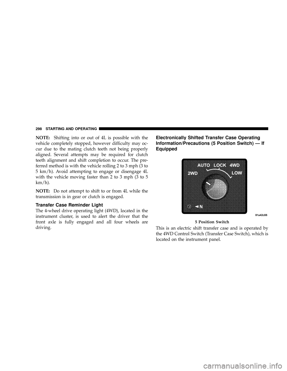
Electronically Shifted Transfer Case Operating
Information/Precautions (5 Position Switch) Ð If
Equipped
This is an electric shift transfer case and is operated by
the 4WD Control Switch (Transfer Case Switch), which is
located on the instrument panel.
5 Position Switch
298 STARTING AND OPERATING
Page 308 of 554

4. After the desired position indicator light is ON (not
flashing), shift transmission back into gear (release clutch
on manual transmissions).
NOTE:If steps 1 or 2 of either the Preferred or Alternate
Procedure are not satisfied prior to attempting the shift or
if they no longer are being met while the shift attempt is
in process then the desired position indicator light will
flash continuously while the original position indicator
light is ON, until all requirements have been met.
NOTE:The ignition key must be ON for a shift to take
place and for the position indicator lights to be operable.
If the key is not ON then the shift will not take place and
no position indicator lights will be on or flashing.
NOTE:If your are leaving your vehicle stored for longer
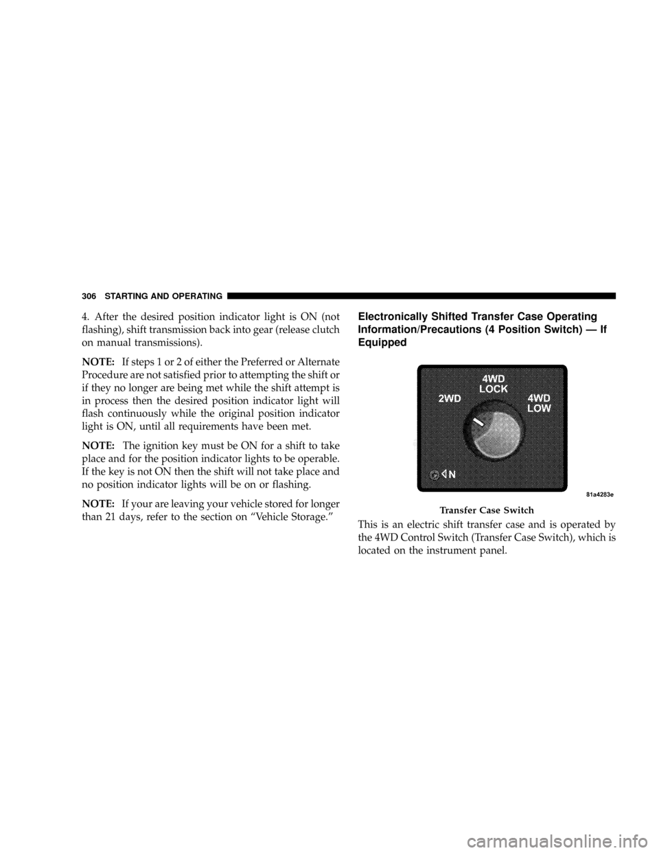
than 21 days, refer to the section on ªVehicle Storage.ºElectronically Shifted Transfer Case Operating
Information/Precautions (4 Position Switch) Ð If
Equipped
This is an electric shift transfer case and is operated by
the 4WD Control Switch (Transfer Case Switch), which is
located on the instrument panel.
Transfer Case Switch
306 STARTING AND OPERATING
Page 320 of 554
PARKING BRAKE
The foot-operated parking brake is positioned below the
lower left corner of the instrument panel. To release the
parking brake, pull the parking brake release handle.
NOTE:The instrument cluster red brake warning light
will come on and flash to indicate that the parking brake
is applied. You must be sure that the parking brake is
fully applied before leaving the vehicle.
Be sure the parking brake is firmly set when parked and
the shift lever is in the PARK position. When parking on
a hill you should apply the parking brake before placing
the shift lever in PARK, otherwise the load on the
transmission locking mechanism may make it difficult to
move the shift lever out of PARK.
Parking Brake Release
318 STARTING AND OPERATING
Page 371 of 554

NOTE:It is particularly important, for you to check the
tire pressure in all of your tires regularly and to maintain
the proper pressure.
The Tire Pressure Monitoring System (TPMS) consists of
the following components:
²Receiver Module
²4 Wheel Sensors
²2 Trigger Modules (mounted in the front wheel-wells)
²ªLight Loadº Reset Switch (located in the instrument
panel)
²Tire Pressure Monitoring Telltale Lamp
Tire Pressure Monitoring Low Pressure Warnings
The Tire Pressure Monitoring Telltale Lamp will
illuminate in the instrument cluster, and an au-
dible chime will be activated when one or more of
the four active road tire pressures are low. Should this
occur, you should stop as soon as possible, check the
inflation pressure of each tire on your vehicle and inflate
each tire to the vehicle's recommended cold placard
pressure value. The system will automatically update
and the Tire Pressure Monitoring Lamp will extinguish
once the updated tire pressures have been received. The
vehicle may need to be driven for up to 10 minutes above
15 mph (25 km/h) to receive this information.
Check TPMS Warnings
The Tire Pressure Monitoring Telltale Warning Light
located in the Instrument Cluster will flash on and off for
75 seconds and will remain on solid when a system fault
is detected. The system fault will also sound a chime. If
STARTING AND OPERATING 369
5