2008 DODGE RAM 3500 DIESEL wheel torque
[x] Cancel search: wheel torquePage 200 of 527
CAUTION!
The TPMS has been optimized for the original
equipment tires and wheels. TPMS pressures and
warning have been established for the tire size
equipped on your vehicle. Undesirable system opera-
tion or sensor damage may result when using re-
placement equipment that is not of the same size,
type, and/or style. Aftermarket wheels can cause
sensor damage. Do not use tire sealant from a can, or
balance beads if your vehicle is equipped with a
TPMS, as damage to the sensors may result.
TPMS ªLight Loadº Reset Switch ± If Equipped
The TPMS ºLight Loadº reset switch allows you to
choose between Light Load vehicle conditions and Max
Load vehicle conditions tire pressures and related TPMS
warning levels. The switch is located in the instrumentpanel, below the climate control panel. For additional
information refer to ªTire Pressure Monitoring System
(TPMS) Ð If Equippedº in section 5 of this manual.
25. Transmission Oil Temperature Warning Light
(Automatic Transmissions Only)
This light indicates that there is excessive trans-
mission fluid temperature that might occur
with severe usage such as trailer towing. It may
also occur when operating the vehicle in a high
torque converter slip condition, such as 4-wheel drive
operation (e.g., snow plowing, off-road operation). If this
light comes on, stop the vehicle and run the engine at idle
or faster, with the transmission in NEUTRAL until the
light goes off.
26. Wait To Start Indicator
The Wait To Start indicator will illuminate when
the ignition is turned to the run position and the
intake manifold temperature is below 66ÉF (19ÉC).
198 UNDERSTANDING YOUR INSTRUMENT PANEL
Page 286 of 527
WARNING!
Do not use the Exhaust Brake feature when driving
in icy or slippery conditions as the increased engine
braking can cause the rear wheels to slide and the
vehicle to swing around with the possible loss of
vehicle control, which may cause an accident possi-
bly resulting in personal injury or death.
NOTE:For optimum braking power it is recommended
to use the Exhaust Brake while in Tow/Haul Mode.
The purpose of the exhaust brake (engine braking) fea-
ture is to supply negative (braking) torque to the engine.
Typically, the engine braking is used for, but not limited
to, vehicle towing applications where vehicle braking can
be achieved by the internal engine power, thereby spar-
ing the mechanical brakes of the vehicle.Benefits of the exhaust brake are:²vehicle driving control
²reduced brake fade
²longer brake life
²faster cab warm-up.
The exhaust brake feature can also be used to reduce the
engine warm up time. To use the exhaust brake as a
warm-up device, the vehicle must be moving less than 5
mph (8 km/h), the exhaust brake switch must be in the
ON position, and the coolant temperature must below
180ÉF (82ÉC) and ambient temperature below 60ÉF (16ÉC).
284 STARTING AND OPERATING
Page 394 of 527
6. Using the wheel wrench, finish tightening the nuts
using a crisscross pattern. Correct nut tightness is 135 ft.
lbs. (183 N´m) torque for 2500/3500 single rear wheel
(SRW) models and 145 ft. lbs. (197 N´m) for 3500 dual rear
wheel models. If in doubt about the correct tightness,
have them checked with a torque wrench by your dealer
or at a service station.
WARNING!
A loose tire or jack thrown forward in a collision or
hard stop could injure someone in the vehicle. Al-
ways stow the jack parts and the extra tire and wheel
in the places provided.
7. Install wheel center cap and remove wheel blocks. Do
not install chrome or aluminum wheel center caps on the
spare wheel. This may result in cap damage.8. Lower the jack to its fully closed position. If the jack
will not lower by turning the dial (thumbwheel) by hand,
it may be necessary to use the jack drive tube in order to
lower the jack. Stow the replaced tire, jack, and tools as
previously described.
9. Adjust the tire pressure when possible.
NOTE:Do not oil wheel studs. For chrome wheels, do
not substitute with chrome plated wheel nuts.Hub Caps/Wheel Covers
The hub caps must be removed before raising the vehicle
off the ground.
For 2500/3500 single rear wheel (SRW) models, use the
blade on the end of the lug wrench to pry the hub cap off.
Insert the blade end into the pryoff notch and carefully
pop off the hub cap with a back and forth motion.
392 WHAT TO DO IN EMERGENCIES
Page 397 of 527
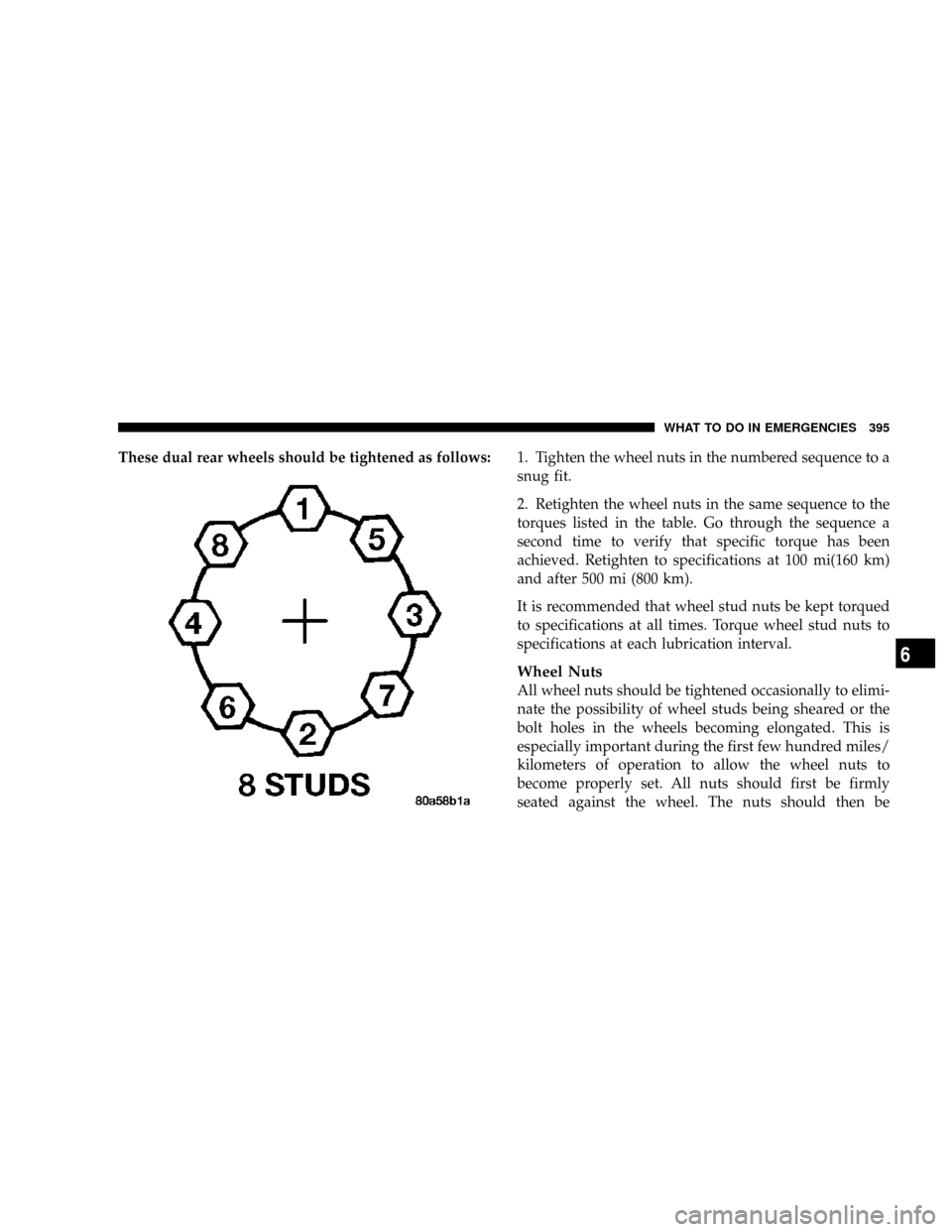
These dual rear wheels should be tightened as follows:1. Tighten the wheel nuts in the numbered sequence to a
snug fit.
2. Retighten the wheel nuts in the same sequence to the
torques listed in the table. Go through the sequence a
second time to verify that specific torque has been
achieved. Retighten to specifications at 100 mi(160 km)
and after 500 mi (800 km).
It is recommended that wheel stud nuts be kept torqued
to specifications at all times. Torque wheel stud nuts to
specifications at each lubrication interval.
Wheel Nuts
All wheel nuts should be tightened occasionally to elimi-
nate the possibility of wheel studs being sheared or the
bolt holes in the wheels becoming elongated. This is
especially important during the first few hundred miles/
kilometers of operation to allow the wheel nuts to
become properly set. All nuts should first be firmly
seated against the wheel. The nuts should then be
WHAT TO DO IN EMERGENCIES 395
6
Page 398 of 527
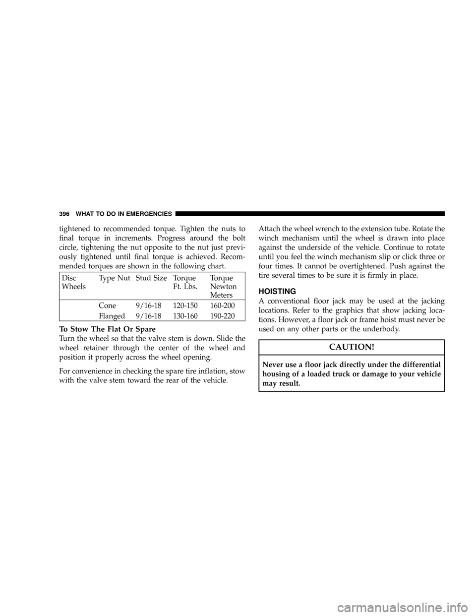
tightened to recommended torque. Tighten the nuts to
final torque in increments. Progress around the bolt
circle, tightening the nut opposite to the nut just previ-
ously tightened until final torque is achieved. Recom-
mended torques are shown in the following chart.
Disc
WheelsType Nut Stud Size Torque
Ft. Lbs.Torque
Newton
Meters
Cone 9/16-18 120-150 160-200
Flanged 9/16-18 130-160 190-220
To Stow The Flat Or Spare
Turn the wheel so that the valve stem is down. Slide the
wheel retainer through the center of the wheel and
position it properly across the wheel opening.
For convenience in checking the spare tire inflation, stow
with the valve stem toward the rear of the vehicle.Attach the wheel wrench to the extension tube. Rotate the
winch mechanism until the wheel is drawn into place
against the underside of the vehicle. Continue to rotate
until you feel the winch mechanism slip or click three or
four times. It cannot be overtightened. Push against the
tire several times to be sure it is firmly in place.
HOISTING
A conventional floor jack may be used at the jacking
locations. Refer to the graphics that show jacking loca-
tions. However, a floor jack or frame hoist must never be
used on any other parts or the underbody.
CAUTION!
Never use a floor jack directly under the differential
housing of a loaded truck or damage to your vehicle
may result.
396 WHAT TO DO IN EMERGENCIES
Page 523 of 527
Inflation Pressures..................... 325
Jacking............................. 387
Life of Tires.......................... 330
Load Capacity.....................320,321
Pressure Monitor System (TPMS)........... 338
Pressure Warning Light.................. 196
Quality Grading....................... 503
Radial.............................. 327
Replacement......................... 331
Rotation............................. 335
Safety...........................316,324
Sizes............................... 317
Snow Tires........................... 335
Spare Tire........................... 386
Spinning............................ 329
Tread Wear Indicators................... 330
Wheel Mounting....................... 387
Wheel Nut Torque..................... 392
Tongue Weight/Trailer Weight.............. 361Torque Converter Clutch.................. 290
Tow Hooks, Emergency................... 401
Tow/Haul............................. 288
Towing............................... 356
24-Hour Towing Assistance............... 102
Disabled Vehicle....................... 402
Guide.............................. 361
Recreational.......................... 375
Weight.............................. 361
Towing Assistance....................... 102
Traction.............................. 307
Traction Control......................... 446
Trailer Towing.......................... 356
Cooling System Tips.................... 369
Hitches............................. 360
Minimum Requirements................. 362
Mirrors...........................87,370
Trailer and Tongue Weight................ 361
Wiring.............................. 365
INDEX 521
10
Page 525 of 527
Warning Lights (Instrument Cluster
Description)........................... 189
Warnings and Cautions..................... 7
Warranty Information..................... 500
Washers, Windshield..................136,434
Washing Vehicle......................... 455
Water
Driving Through...................... 307
Wheel Alignment and Balance............... 332
Wheel and Wheel Trim.................... 457
Wheel and Wheel Trim Care................ 457
Wheel Changing........................ 386
Wheel Cover........................... 392
Wheel Mounting........................ 387
Wheel Nut Torque....................392,395Wind Buffeting.......................34,160
Window Fogging........................ 260
Windows.............................. 32
Power............................... 32
Rear Sliding........................34,174
Windshield Defroster..................251,253
Windshield Washers................135,136,434
Fluid............................135,434
Windshield Wiper Blades.................. 433
Windshield Wipers....................... 135
Wiper Blade Replacement.................. 433
Wipers, Intermittent...................... 136
YES EssentialstFabric Cleaning Procedure...... 457
INDEX 523
10