2008 DODGE RAM 2500 DIESEL mileage
[x] Cancel search: mileagePage 62 of 527

In the event that an investigation is undertaken by
DaimlerChrysler Corporation (regardless of initiative),
the company or its designated representative will first
obtain permission of the appropriate custodial entity for
the vehicle (usually the vehicle owner or lessee) before
accessing the electronic data stored, unless ordered to
download data by a court with legal jurisdiction (i.e.,
pursuant to a warrant). A copy of the data will be
provided to the custodial entity upon request. General
data that does not identify particular vehicles or crashes
may be released for incorporation in aggregate crash
databases, such as those maintained by the U.S. govern-
ment and various states. Data of a potentially sensitive
nature, such as would identify a particular driver, ve-
hicle, or crash, will be treated confidentially. Confidential
data will not be disclosed by DaimlerChrysler
Corporation to any third party except when:1. Used for research purposes, such as to match data
with a particular crash record in an aggregate database,
provided confidentiality of personal data is thereafter
preserved
2. Used in defense of litigation involving a
DaimlerChrysler Corporation product
3. Requested by police under a legal warrant
4. Otherwise required by law
Data Parameters that May Be Recorded:
²Diagnostic trouble code(s) (DTC's) and warning lamp
status for electronically-controlled safety systems, in-
cluding the airbag system
²Airbag disable lamp status (if equipped)
²9Time9of airbag deployment (in terms of ignition
cycles and vehicle mileage)
60 THINGS TO KNOW BEFORE STARTING YOUR VEHICLE
Page 194 of 527

CAUTION!
Do not leave your vehicle unattended with the en-
gine running as you would not be able to react to the
temperature indicator if the engine overheats.
NOTE:Engine idle speed will automatically increase to
1000 rpm at elevated coolant temperatures to improve
engine cooling.
NOTE:If the gauge pointer moves to either extreme of
the gauge, the ªCheck Gaugesº indicator will illuminate
and a single chime will sound.
13. Security Light
The light will flash rapidly for approximately 16 seconds
when the Vehicle Theft Alarm is arming. The light willflash at a slower rate after the alarm is set. The Security
Light will also come on for about two seconds when the
ignition is first turned ON.
14. Transmission Range Indicator (Automatic
Transmissions Only)
When the gear selector lever is moved on vehicles with
the 68RFE transmission, this indicator shows the auto-
matic transmission gear range selected (P R N D). Ve-
hicles equipped with Auto-6/Electronic Range Select
(ERS) will display the selection of the desired top gear, in
the position next to the D (Drive).
15. Odometer/Trip Odometer
The odometer shows the total distance the vehicle has
been driven. U.S. federal regulations require that upon
transfer of vehicle ownership, the seller certify to the
purchaser the correct mileage that the vehicle has been
driven. Therefore, if the odometer reading is changed
192 UNDERSTANDING YOUR INSTRUMENT PANEL
Page 195 of 527

during repair or replacement, be sure to keep a record of
the reading before and after the service so that the correct
mileage can be determined.
The two trip odometers show individual trip mileage. To
switch from odometer to trip odometers, press and
release the Trip Odometer button.
To reset a trip odometer, display the desired trip odom-
eter to be reset then push and hold the button until the
display resets (approximately two seconds).
Vehicle Warning Messages
When the appropriate conditions exist, messages such as
ªdoorº (indicates that a door(s) may be ajar), ªgASCAPº
(which indicates that your gas cap is possibly loose or
damaged), and ªnoFUSEº (indicates that the IOD fuse is
removed from the Integrated Power Module), will dis-
play in the odometer.NOTE:Most warnings will display in the EVIC (Elec-
tronic Vehicle Information Center).
NOTE:There is also an engine hour function. This
indicates the total number of hours the engine has been
running. To display the engine hours perform the follow-
ing: Place the ignition in RUN, but do not start the
engine. With the odometer value displayed, hold the trip
button down for a period of 6 seconds. The odometer will
change to trip value first, then it will display the engine
hour value. The engine hours will be displayed for a
period of 30 seconds until the ignition is turned off or the
engine is started.
16. Front Fog Light Indicator Ð If Equipped
This light shows when the front fog lights are ON.
UNDERSTANDING YOUR INSTRUMENT PANEL 193
4
Page 413 of 527

CAUTION!
To maintain your vehicle safely follow these guide-
lines:
²Watch your vehicle's mileage and check your
Maintenance Schedules regularly for required ser-
vicing. Excessive wear or damage to certain vehicle
components can result if required services are not
performed.
²If you have your vehicle undercoated, inspect for
undercoating material on the propeller shafts.
Such material could cause the shafts to become
unbalanced and result in drivetrain vibrations.
Remove any undercoating with solvent.
²If you have your vehicle undercoated, make sure
no undercoating material is sprayed on the ex-
haust system or components of the seat belt
system.NOTE:It is not possible for the manufacturer and
Cummins, Inct. to anticipate every possible circumstance
that can involve a potential hazard.
MAINTAINING YOUR VEHICLE 411
7
Page 423 of 527

The clear plastic housing on the Filter MinderŸ (If
Equipped), allows you to view the amount of air pressure
drop across the filter element. It consists of a diaphragm
and a calibrated spring sealed inside the plastic housing.
As the air cleaner filter becomes clogged and air pressure
drop across the filter element increases, a yellow disc
travels along a graduated scale on the side of the Filter
MinderŸ.
The yellow disc will always show the greatest restriction
experienced by the filter element. When the disc reaches
the red zone, the filter element may need to be replaced.
There is no other time or mileage interval for changing
the air cleaner filter element.
After a new filter element is inserted, press the rubber
button on the top of the Filter MinderŸ (if equipped).
This action will reset the yellow disc to the clean position.CAUTION!
When using an engine cleaner or a degreaser, be sure
to wrap and tape the Filter MinderŸ to protect the
plastic housing from damage and discoloration.
CAUTION!
Many aftermarket performance air filter elements do
not adequately filter the air entering the engine. Use
of such filters can severely damage your engine.
MAINTAINING YOUR VEHICLE 421
7
Page 444 of 527

²Make sure that the radiator and coolant recovery
bottle overflow hoses are not kinked or obstructed.
²Keep the front of the radiator clean. If your vehicle is
equipped with air conditioning, keep the front of the
condenser clean also.
²Do not change the thermostat for summer or winter
operation. If replacement is ever necessary, install
ONLY the correct type thermostat. Other designs may
result in unsatisfactory coolant performance, poor gas
mileage, and increased emissions.
Fan
Inspection
Check the fan for cracks and bent or broken blades. If any
of these conditions exist, you must replace the fan. Make
sure it is securely mounted.NOTE:This service procedure must be performed by a
trained service technician. Make arrangements with your
authorized dealer for this inspection.
Charge Air Cooler (Inter-Cooler)
The charge air cooler is positioned between the radiator
and the air conditioner condenser. Air enters the engine
through the air cleaner and passes through the turbo-
charger where it is pressurized. This pressurized air
rapidly reaches high temperature. The air is then directed
through a hose to the charge air cooler and through
another hose to the intake manifold of the engine. The air
entering the engine has been cooled by about 50 to 100
degrees Fahrenheit. This cooling process enables more
efficient burning of fuel resulting in fewer emissions.
442 MAINTAINING YOUR VEHICLE
Page 456 of 527

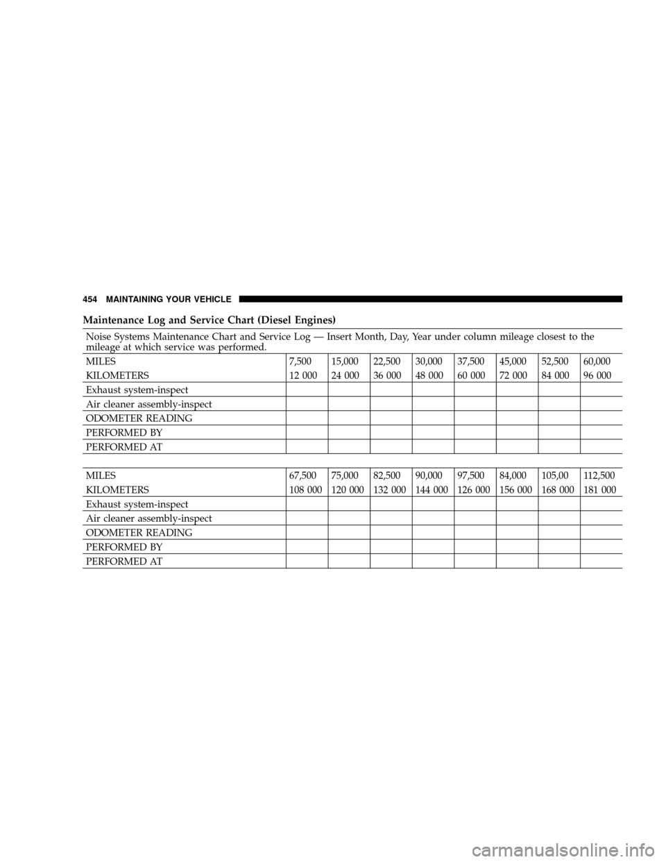
Maintenance Log and Service Chart (Diesel Engines)
Noise Systems Maintenance Chart and Service Log Ð Insert Month, Day, Year under column mileage closest to the
mileage at which service was performed.
MILES 7,500 15,000 22,500 30,000 37,500 45,000 52,500 60,000
KILOMETERS 12 000 24 000 36 000 48 000 60 000 72 000 84 000 96 000
Exhaust system-inspect
Air cleaner assembly-inspect
ODOMETER READING
PERFORMED BY
PERFORMED AT
MILES 67,500 75,000 82,500 90,000 97,500 84,000 105,00 112,500
KILOMETERS 108 000 120 000 132 000 144 000 126 000 156 000 168 000 181 000
Exhaust system-inspect
Air cleaner assembly-inspect
ODOMETER READING
PERFORMED BY
PERFORMED AT
454 MAINTAINING YOUR VEHICLE
Page 486 of 527

EMISSION CONTROL SYSTEM MAINTENANCE
The Scheduled maintenance services, listed inbold type
in this section (Section 8) must be done at the times or
mileages specified to assure the continued proper func-
tioning of the emission control system. These, and all
other maintenance services included in this manual,
should be done to provide best vehicle performance and
reliability. More frequent maintenance may be needed for
vehicles in severe operating conditions, such as dusty
areas and very short trip driving.
Inspection and service also should be done anytime a
malfunction is suspected.
NOTE:Maintenance, replacement, or repair of the emis-
sion control devices and systems on your vehicle may be
performed by any automotive repair establishment or
individual using any automotive part which has been
certified pursuant to U.S. EPA or, in the State of Califor-
nia, California Air Resources Board regulations.
MAINTENANCE SCHEDULES Ð 6.7L TURBO
DIESEL
CAUTION!
Failure to perform the required maintenance items
may result in damage to the vehicle.
At Each Stop for Fuel
²Check the engine oil level about 30 minutes after a
fully warmed engine is shut off. Checking the oil level
while the vehicle is on level ground will improve the
accuracy of the oil level reading. Add oil only when
the level is at or below the ADD or MIN mark.
²Check the windshield washer solvent and add if
required. When refilling the washer fluid reservoir,
484 MAINTENANCE SCHEDULES
8
M
A
I
N
T
E
N
A
N
C
E
S
C
H
E
D
U
L
E
S