2008 CHRYSLER TOWN AND COUNTRY stop start
[x] Cancel search: stop startPage 87 of 531
²The passenger seat belts are equipped with cinching
latch plates, which are designed to keep the lap portion
tight around the child restraint so that it is not neces-
sary to use a locking clip. Pulling up on the shoulder
portion of the lap/shoulder belt will tighten the belt.
The cinching latch plate will keep the belt tight, how-
ever, any seat belt system will loosen with time, so
check the belt occasionally and pull it tight if necessary.
²In the rear seat, you may have trouble tightening the
lap/shoulder belt on the child restraint because the
buckle or latch plate is too close to the belt path
opening on the restraint. Disconnect the latch plate
from the buckle and twist the short buckle end of the
belt several times to shorten it. Insert the latch plate
into the buckle with the release button facing out.
²If the belt still can't be tightened, or if pulling and
pushing on the restraint loosens the belt, disconnect
the latch plate from the buckle, turn the bucklearound, and insert the latch plate into the buckle
again. If you still can't make the child restraint secure,
try a different seating position.
²Buckle the child into the seat according to the child
restraint manufacturer's directions.
²When your child restraint is not in use, secure it in the
vehicle with the seat belt or remove it from the vehicle.
Don't leave it loose in the vehicle. In a sudden stop or
collision, it could strike the occupants or seatbacks and
cause serious personal injury.
Lower Anchors and Tether for CHildren (LATCH)
Each vehicle, except commercial cargo vehicles, is
equipped with the child restraint anchorage system
called LATCH, which stands for Lower Anchors and
Tether for CHildren. Two LATCH child restraint anchor-
age systems are installed on all second-row seats and in
the center position on all 3rd row fold-in-floor seats.
Second-row seats also feature tether strap anchorages,
THINGS TO KNOW BEFORE STARTING YOUR VEHICLE 85
2
Page 200 of 531
CUP HOLDERS AND CONVENIENCE TRAY
DRAWER
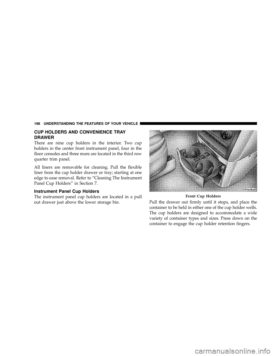
There are nine cup holders in the interior. Two cup
holders in the center front instrument panel, four in the
floor consoles and three more are located in the third row
quarter trim panel.
All liners are removable for cleaning. Pull the flexible
liner from the cup holder drawer or tray; starting at one
edge to ease removal. Refer to ªCleaning The Instrument
Panel Cup Holdersº in Section 7.
Instrument Panel Cup Holders
The instrument panel cup holders are located in a pull
out drawer just above the lower storage bin.Pull the drawer out firmly until it stops, and place the
container to be held in either one of the cup holder wells.
The cup holders are designed to accommodate a wide
variety of container types and sizes. Press down on the
container to engage the cup holder retention fingers.Front Cup Holders
198 UNDERSTANDING THE FEATURES OF YOUR VEHICLE
Page 228 of 531
INSTRUMENT CLUSTER DESCRIPTIONS
1. Fuel Gauge
The pointer shows the level of fuel in the fuel tank when
the ignition switch is in the ON position.
2. Low Fuel Light
When the fuel level reaches approximately 2.0 gals
(7.8 L) this light will turn on and remain on until
fuel is added.
3. Electronic Throttle Control (ETC.) Light
This light informs you of a problem with the
Electronic Throttle Control system. If a prob-
lem is detected, the light will come on while the
engine is running. Cycle the ignition key when
the vehicle has completely stopped and the gear selector
is placed in the PARK position. The light should turn off.
If the light remains lit with the engine running your
vehicle will usually be drivable, however, see your
authorized dealer for service as soon as possible. If thelight is flashing when the engine is running, immediate
service is required and you may experience reduced
performance, an elevated/rough idle or engine stall and
your vehicle may require towing. The light will come ON
when the ignition is first turned on and remain on briefly
as a bulb check. If the light does not come on during
starting, have the system checked by an authorized
dealer.
4. Voltage Light
This light monitors the electrical system voltage.
The light should turn on momentarily as the
engine is started. If the light stays on or turns on while
driving, it indicates a problem with the charging system.
Immediate service should be obtained.
226 UNDERSTANDING YOUR INSTRUMENT PANEL
Page 229 of 531
5. Tire Pressure Monitoring Telltale Lamp Ð If
Equipped
Each tire, including the spare (if provided),
should be checked monthly when cold and
inflated to the inflation pressure recommended
by the vehicle manufacturer on the vehicle
placard or tire inflation pressure label. (If your vehicle
has tires of a different size than the size indicated on the
vehicle placard or tire inflation pressure label, you should
determine the proper tire inflation pressure for those
tires.)
As an added safety feature, your vehicle has been
equipped with a Tire Pressure Monitoring System
(TPMS) that illuminates a low tire pressure telltale when
one or more of your tires is significantly under-inflated.
Accordingly, when the low tire pressure telltale illumi-
nates, you should stop and check your tires as soon as
possible, and inflate them to the proper pressure. Driving
on a significantly under-inflated tire causes the tire tooverheat and can lead to tire failure. Underinflation also
reduces fuel efficiency and tire tread life, and may affect
the vehicle's handling and stopping ability.
NOTE:Please note that the TPMS is not a substitute for
proper tire maintenance, and it is the driver 's responsi-
bility to maintain correct tire pressure, even if underin-
flation has not reached the level to trigger illumination of
the TPMS low tire pressure telltale.
Your vehicle has also been equipped with a TPMS
malfunction indicator to indicate when the system is not
operating properly. The TPMS malfunction indicator is
combined with the low tire pressure telltale. When the
system detects a malfunction, the telltale will flash for
approximately one minute and then remain continuously
illuminated. This sequence will continue upon subse-
quent vehicle start-ups as long as the malfunction exists.
When the malfunction indicator is illuminated, the sys-
tem may not be able to detect or signal low tire pressure
UNDERSTANDING YOUR INSTRUMENT PANEL 227
4
Page 231 of 531
For additional information on Tire Pressures, refer to
Section 5 Ð Starting and Operating, ªTire Inflation
Pressuresº of this manual.
6. Oil Pressure Warning Light
This light shows low engine oil pressure. The light
should turn on momentarily when the engine is
started. If the light turns on while driving, stop the
vehicle and shut off the engine as soon as possible. A
chime will sound for four minutes when this light turns
on.
Do not operate the vehicle until the cause is corrected.
This light does not show how much oil is in the engine.
The engine oil level must be checked under the hood.
7. Engine Temperature Warning Light
This light warns of an overheated engine condi-
tion. If the engine is critically hot, a continuouschime will sound for four minutes. After the chime turns
off, the engine will still be critically hot until the light
turns off.
8. Speedometer
Indicates vehicle speed.
9. Turn Signal Indicators
The arrow will flash with the exterior turn signal
when the turn signal lever is operated.
If the vehicle electronics sense that the vehicle has
traveled about one mile with the turn signals on, a
continuous chime will sound to alert you to turn the
signals off. If either indicator flashes at a rapid rate, check
for a defective outside light bulb.
10. Electronic Stability Program (ESP) Indicator Light
The malfunction lamp for the ESP is combined
with BAS. The yellow ªESP/BAS Warning
Lampº comes on when the ignition switch is
UNDERSTANDING YOUR INSTRUMENT PANEL 229
4
Page 298 of 531
previous track in the list; if you press this button at any
other time in the current track it will go back to the
beginning of the track.
If the right (up) button is pressed during Play mode, it
will go to the next track in the list.
INFO Button
Press the INFO button while a track is playing to see the
information (Track Title, Artist, Album, etc.) for that
track. Each press of the INFO button will take you to the
next screen of data for that track. Once you have seen all
of the screens, the last press of the INFO button will take
you back to the Play mode screen on the radio.
REPEAT Button
Press the REPEAT button to repeat the current playing
track.SCAN Button
Pressing the SCAN button will play the first five seconds
of each track in the current list and then forward to the
next song. To stop the SCAN mode and start playing the
desired track, press the SCAN button again.
During the SCAN mode, you can also press the SEEK
button to the left or right to go to the previous or next
tracks.
RND (Random) Button (RES/REL Radios Only)
Pressing the RND button will switch between the shuffle
on and shuffle off modes of the iPodt. If the RND icon is
showing on the radio display then the Shuffle mode is on.
List or Browse Mode
During Play mode, pressing any of the following buttons
will take you to List mode. List mode enables you to
scroll through the list of menus and tracks on the iPodt
device.
296 UNDERSTANDING YOUR INSTRUMENT PANEL
Page 332 of 531
AUTOMATIC TRANSMISSION
CAUTION!
Damage to the transmission may occur if the follow-
ing precautions are not observed:
²Shift the gear selector lever into PARK only after
the vehicle has come to a complete stop.
²Do not shift the gear selector lever from RE-
VERSE, PARK, or NEUTRAL into any forward
gear when the engine is above idle speed.
²Before shifting the gear selector lever into any
gear, make sure your foot is firmly on the brake
pedal.
NOTE:You MUST press and hold the brake pedal down
while shifting out of PARK.
WARNING!
It is dangerous to shift the gear selector lever out of
PARK or NEUTRAL if the engine speed is higher
than idle speed. If your foot is not firmly on the
brake pedal, the vehicle could accelerate quickly
forward or in reverse. You could lose control of the
vehicle and hit someone or something. Only shift
into gear when the engine is idling normally and
when your right foot is firmly on the brake pedal.
Brake/Transmission Interlock System
This system holds the shift lever in the PARK position
when the ignition switch is in the LOCK position. It also
prevents you, once the engine is started, from moving the
gear selector lever out of PARK and into any gear unless
the brake pedal is pressed. This system is active only
330 STARTING AND OPERATING
Page 333 of 531
while the ignition switch is in the ON position. Always
press the brake pedal first before moving the gear selec-
tor lever out of PARK.
Automatic Transmission Ignition Interlock System
For electrical system malfunctions, there is an override
for the interlock system. In order to override this system,
remove the cover located to the top right of the gear
selector lever in the instrument panel. The override can
be activated by pressing the white-colored tab, which can
be accessed through the hole in the instrument panel.
While the override is pressed, the gear selector lever can
be moved out of the PARK position without pressing the
brake pedal. After operation, return the cover to its
original position.
This system prevents the key from being removed unless
the gear selector lever is in PARK. It also prevents shifting
the gear selector lever out of PARK unless the key is in
the LOCK/OFF or ON positions.NOTE:If a malfunction occurs, the system will trap the
key in the ignition cylinder to warn you that this safety
feature is inoperable. The engine can be started and
stopped but the key cannot be removed until you obtain
service.
Four-Speed or Six-Speed Automatic
Transmission
The electronically controlled transmission provides a
precise shift schedule. The transmission electronics are
self-calibrating; therefore, the first few shifts on a new
vehicle may be somewhat abrupt. This is a normal
condition, and precision shifts will develop within a few
hundred miles (kilometers).
The transmission has only PRND shift positions. Down-
shifts are carried out by an Electronic Range Select (ERS)
by moving the leverÐ/+while in the DRIVE position,
STARTING AND OPERATING 331
5