Page 403 of 596

Heavy-Duty Trailer Wiring Harness
Package
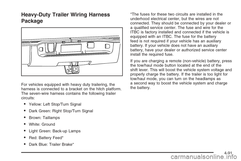
For vehicles equipped with heavy duty trailering, the
harness is connected to a bracket on the hitch platform.
The seven-wire harness contains the following trailer
circuits:
Yellow: Left Stop/Turn Signal
Dark Green: Right Stop/Turn Signal
Brown: Taillamps
White: Ground
Light Green: Back-up Lamps
Red: Battery Feed*
Dark Blue: Trailer Brake**The fuses for these two circuits are installed in the
underhood electrical center, but the wires are not
connected. They should be connected by your dealer or
a quali�ed service center. The fuse and wire for the
ITBC is factory installed and connected if the vehicle is
equipped with an ITBC. The fuse for the battery
feed is not required if your vehicle has an auxiliary
battery. If your vehicle does not have an auxiliary
battery, have your dealer or authorized service center
install the required fuse.
If you are charging a remote (non-vehicle) battery, press
the tow/haul mode button located at the end of the
shift lever. This will boost the vehicle system voltage and
properly charge the battery. If the trailer is too light for
tow/haul mode, you can turn on the headlamps as
a second way to boost the vehicle system and charge
the battery.
4-91
Page 404 of 596
Camper/Fifth-Wheel Trailer Wiring Package
The seven-wire camper harness is located under the
front edge of the pickup box on the driver’s side of the
vehicle, attached to the frame bracket. A connector
will have to be added to the wiring harness which
connects to the camper.
The harness contains the following camper/trailer
circuits:
Yellow: Left Stop/Turn Signal
Dark Green: Right Stop/Turn Signal
Brown: Taillamps
White: Ground
Light Green: Back-up Lamps
Red: Battery Feed
Dark Blue: Trailer BrakeIf your vehicle is equipped with the “Heavy-Duty
Trailering” option, please refer to “Heavy-Duty Trailer
Wiring Package” earlier in this section.
When the camper-wiring harness is ordered without the
heavy-duty trailering package, an eight-wire harness
with a seven-pin connector is located at the rear of the
vehicle and is tied to the vehicle’s frame.
4-92
Page 405 of 596

Electric Brake Control Wiring
Provisions
These wiring provisions are included with your vehicle
as part of the trailer wiring package. These provisions
are for an electric brake controller. The instrument panel
contains blunt cut wires near the data link connector
for the trailer brake controller. The harness contains the
following wires:
Dark Blue: Brake Signal to Trailer Connector
Red/Black: Battery
Light Blue/White: Brake Switch
White: Ground
It should be installed by your dealer or a quali�ed
service center.
If your vehicle is equipped with an ITBC, the blunt cuts
exist, but are not connected further in the harness. If
you install an aftermarket trailer brake controller,
the ITBC must be disconnected. Do not power both
ITBC and aftermarket controllers to control the trailer
brakes at the same time.
Auxiliary Battery
The auxiliary battery provision can be used to supply
electrical power to additional equipment that you may
choose to add, such as a slide-in camper. If your vehicle
has this provision, this relay will be located on the driver’s
side of the vehicle, next to the underhood electrical
center.
Be sure to follow the proper installation instructions that
are included with any electrical equipment that you install.
Notice:Leaving electrical equipment on for
extended periods will drain the battery. Always turn
off electrical equipment when not in use and do
not use equipment that exceeds the maximum
amperage rating for the auxiliary battery provision.
Trailer Recommendations
You must subtract your hitch loads from the CWR for
your vehicle. Weigh your vehicle with the trailer
attached, so that you won’t go over the GVWR or
GAWR. If you are using a weight-distributing hitch,
weigh the vehicle without the spring bars in place.
You’ll get the best performance if you spread out the
weight of your load the right way, and if you choose the
correct hitch and trailer brakes.
For more information, seeTowing a Trailer on
page 4-55.
4-93