2008 CHEVROLET IMPALA seats
[x] Cancel search: seatsPage 143 of 400
Reading Lamps
The vehicle has reading lamps that also act as the
dome lamp. Press the button to turn them on and off.
Mirror Reading Lamps
Your vehicle has reading lamps on the rearview mirror.
Push the button to turn the reading lamps on and off.
Electric Power Management
The vehicle has Electric Power Management (EPM)
that estimates the battery’s temperature and state
of charge. It then adjusts the voltage for best
performance and extended life of the battery.
When the battery’s state of charge is low, the voltage is
raised slightly to quickly put the charge back in. When
the state of charge is high, the voltage is lowered slightly
to prevent overcharging. If the vehicle has a voltmeter
gage or a voltage display on the Driver Information
Center (DIC), you may see the voltage move up or
down. This is normal. If there is a problem, an alert
will be displayed.The battery can be discharged at idle if the electrical
loads are very high. This is true for all vehicles.
This is because the generator (alternator) may not be
spinning fast enough at idle to produce all the power that
is needed for very high electrical loads.
A high electrical load occurs when several of the
following loads are on: headlamps, high beams, fog
lamps, rear window defogger, climate control fan at
high speed, heated seats, engine cooling fans, trailer
loads, and loads plugged into accessory power outlets.
EPM works to prevent excessive discharge of the
battery. It does this by balancing the generator’s output
and the vehicle’s electrical needs. It can increase
engine idle speed to generate more power, whenever
needed. It can temporarily reduce the power demands of
some accessories.
Normally, these actions occur in steps or levels, without
being noticeable. In rare cases at the highest levels of
corrective action, this action may be noticeable to the
driver. If so, a Driver Information Center (DIC) message
might be displayed, such as Battery Saver Active or
Service Battery Charging System. If this message is
displayed, it is recommended that the driver reduce the
electrical loads as much as possible. SeeDIC Warnings
and Messages on page 3-52.
3-19
Page 146 of 400
Climate Controls
Climate Control System
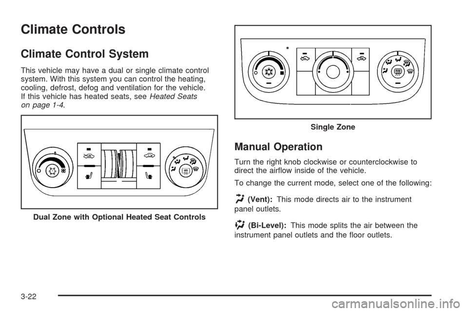
This vehicle may have a dual or single climate control
system. With this system you can control the heating,
cooling, defrost, defog and ventilation for the vehicle.
If this vehicle has heated seats, seeHeated Seats
on page 1-4.
Manual Operation
Turn the right knob clockwise or counterclockwise to
direct the air�ow inside of the vehicle.
To change the current mode, select one of the following:
H(Vent):This mode directs air to the instrument
panel outlets.
)(Bi-Level):This mode splits the air between the
instrument panel outlets and the �oor outlets. Dual Zone with Optional Heated Seat Controls
Single Zone
3-22
Page 149 of 400
Rear Window Defogger
The rear window defogger uses a warming grid to
remove fog from the rear window.
<(Rear Window Defogger):The rear window
defogger turns off automatically after it has been
activated for 10 minutes. It can be turned off manually,
by pressing the button again or by turning the ignition
to the LOCK/OFF position. If additional window clearing
is required, the rear window defogger can be turned
on again for additional window clearing. The length of
defogger operation will increase if the vehicle is
being driven.
If your vehicle has heated outside rearview mirrors,
the mirrors will heat to help clear fog or frost from the
surface of the mirror when the rear window defog button
is pressed. SeeOutside Power Mirrors on page 2-37.
Do not drive the vehicle until all the windows are clear.
Notice:Do not use anything sharp on the inside
of the rear window. If you do, you could cut or
damage the warming grid, and the repairs would not
be covered by your warranty. Do not attach a
temporary vehicle license, tape, a decal or anything
similar to the defogger grid.
Outlet Adjustment
Use the thumbwheel located below or to the side of
the outlet, to change the direction of the air �ow.
Operation Tips
Clear away any ice, snow or leaves from the air
inlets at the base of the windshield that may
block the �ow of air into your vehicle.
Use of non-GM approved hood de�ectors may
adversely affect the performance of the system.
Keep the path under the front seats clear of objects
to help circulate the air inside your vehicle more
effectively.
If the air�ow seems low when the fan is at the
highest setting, the passenger compartment
air �lter, if equipped, may need to replaced. For
more information, seePassenger Compartment Air
Filter on page 3-26andScheduled Maintenance
on page 6-4.
If fogging reoccurs while in vent or bi-level modes
with mild temperature throughout the vehicle, turn
on the air conditioner to reduce windshield fogging.
3-25
Page 175 of 400
Compass Calibration
The compass can be manually calibrated. Only calibrate
the compass in a magnetically clean and safe location,
such as an open parking lot, where driving the vehicle
in circles is not a danger. It is suggested to calibrate
away from tall buildings, utility wires, manhole covers,
or other industrial structures, if possible.
If CAL should ever appear in the DIC display,
the compass should be calibrated.
If the DIC display does not show a heading, for example,
N for North, or the heading does not change after
making turns, there may be a strong magnetic �eld
interfering with the compass. Such interference may be
caused by a magnetic CB or cell phone antenna
mount, a magnetic emergency light, magnetic note pad
holder, or any other magnetic item. Turn off the
vehicle, move the magnetic item, then turn on the
vehicle and calibrate the compass.To calibrate the compass, use the following procedure:Compass Calibration Procedure
1. Before calibrating the compass, make sure the
compass zone is set to the variance zone in
which the vehicle is located. See “Compass
Variance (Zone) Procedure” earlier in this section.
Do not operate any switches such as window,
sunroof, climate controls, seats, etc. during
the calibration procedure.
2. Press the vehicle information button until
PRESS
VTO CALIBRATE COMPASS displays.
3. Press the set/reset button to start the compass
calibration.
4. The DIC will display CALIBRATING: DRIVE IN
CIRCLES. Drive the vehicle in tight circles at
less than 5 mph (8 km/h) to complete the calibration.
The DIC will display CALIBRATION COMPLETE
for a few seconds when the calibration is complete.
The DIC display will then return to PRESS
VTO
CALIBRATE COMPASS.
3-51
Page 237 of 400
Never exceed the GVWR for your vehicle or the
Gross Axle Weight Rating (GAWR) for either
the front or rear axle.
If the vehicle is going to carry a heavy load,
spread it out. See “Steps for Determining Correct
Load Limit” earlier in this section.
{CAUTION:
Do not load your vehicle any heavier than
the Gross Vehicle Weight Rating (GVWR),
or either the maximum front or rear Gross
Axle Weight Rating (GAWR). If you do,
parts on your vehicle can break, and it
can change the way your vehicle handles.
These could cause you to lose control
and crash. Also, overloading can shorten
the life of your vehicle.
Notice:Overloading your vehicle may cause
damage. Repairs would not be covered by your
warranty. Do not overload your vehicle.If things like suitcases, tools, packages, or
anything else are put inside the vehicle, they will
go as fast as the vehicle goes. If you have to stop
or turn quickly, or if there is a crash, they will
keep going.
{CAUTION:
Things you put inside your vehicle can
strike and injure people in a sudden stop
or turn, or in a crash.
Put things in the trunk of your vehicle.
In a trunk, put them as far forward as
you can. Try to spread the weight
evenly.
Never stack heavier things, like
suitcases, inside the vehicle so that
some of them are above the tops of
the seats.
Do not leave an unsecured child
restraint in your vehicle.
When you carry something inside the
vehicle, secure it whenever you can.
Do not leave a seat folded down
unless you need to.
4-25
Page 304 of 400

(C) Aspect Ratio:A two-digit number that
indicates the tire height-to-width measurements.
For example, if the tire size aspect ratio is 60,
as shown in item C of the illustration, it would
mean that the tire’s sidewall is 60 percent as high
as it is wide.
(D) Construction Code
:A letter code is used to
indicate the type of ply construction in the tire.
The letter R means radial ply construction;
the letter D means diagonal or bias ply
construction; and the letter B means belted-bias
ply construction.
(E) Rim Diameter
:Diameter of the wheel in
inches.
(F) Service Description
:These characters
represent the load range and speed rating of the
tire. The load index represents the load carry
capacity a tire is certi�ed to carry. The load index
can range from 1 to 279. The speed rating is
the maximum speed a tire is certi�ed to carry a
load. Speed ratings range from A to Z.
Tire Terminology and De�nitions
Air Pressure:The amount of air inside the
tire pressing outward on each square inch of the
tire. Air pressure is expressed in pounds per
square inch (psi) or kilopascal (kPa).
Accessory Weight
:This means the combined
weight of optional accessories. Some examples of
optional accessories are, automatic transmission,
power steering, power brakes, power windows,
power seats, and air conditioning.
Aspect Ratio
:The relationship of a tire’s height
to its width.
Belt
:A rubber coated layer of cords that is
located between the plies and the tread. Cords
may be made from steel or other reinforcing
materials.
Bead
:The tire bead contains steel wires wrapped
by steel cords that hold the tire onto the rim.
Bias Ply Tire
:A pneumatic tire in which the plies
are laid at alternate angles less than 90 degrees
to the centerline of the tread.
5-58
Page 346 of 400

Fuses Usage
PWR/SEAT Power Seats
PWR/WNDW Power Window
RAP Retained Accessory Power
HTD/SEAT Heated Seats
AUX Auxiliary Outlets
AMP Ampli�er
S/ROOF Sunroof
XM XM™ Radio
CNSTR Canister
Fuses Usage
DR/LCK Door Locks
PWR/MIR Power Mirrors
AIRBAG Airbags
TRUNK Trunk
TRUNK Trunk Relay
Underhood Fuse Block
The underhood fuse block is located in the engine
compartment. SeeEngine Compartment Overview on
page 5-14for more information on location.
Notice:Spilling liquid on any electrical components
on your vehicle may damage it. Always keep the
covers on any electrical component.
5-100
Page 392 of 400

G
Gage
Engine Coolant Temperature.........................3-38
Fuel..........................................................3-43
Speedometer..............................................3-29
Tachometer.................................................3-29
Garage Door Opener.......................................2-41
Gasoline
Octane........................................................ 5-6
Speci�cations............................................... 5-6
Glove Box.....................................................2-48
GM Mobility Reimbursement Program.................. 7-6
H
Hazard Warning Flashers................................... 3-6
Head Restraints............................................... 1-7
Headlamp
Aiming.......................................................5-47
Headlamp Wiring............................................5-99
Headlamps
Bulb Replacement.......................................5-47
Daytime Running Lamps/Automatic Headlamp
System...................................................3-16
Delayed.....................................................3-15
Exterior Lamps............................................3-14Headlamps (cont.)
Flash-to-Pass............................................... 3-9
Halogen Bulbs............................................5-47
Headlamps, Front Turn Signal, Sidemarker,
and Parking Lamps..................................5-48
High/Low Beam Changer................................ 3-8
Heated Seats................................................... 1-4
Heater...........................................................3-22
Highbeam On Light.........................................3-43
Highway Hypnosis...........................................4-14
Hill and Mountain Roads..................................4-15
Hood
Checking Things Under................................5-12
Release.....................................................5-13
Horn............................................................... 3-6
How to Wear Safety Belts Properly...................1-15
I
Ignition Positions.............................................2-22
Infants and Young Children, Restraints...............1-34
In�ation - Tire Pressure...................................5-61
Instrument Panel
Overview..................................................... 3-4
Instrument Panel (I/P)
Brightness..................................................3-17
Cluster.......................................................3-28
6