2008 CHEVROLET EXPRESS PASSANGER seats
[x] Cancel search: seatsPage 78 of 414

Adding Equipment to Your
Airbag-Equipped Vehicle
Q:Is there anything I might add to or change
about the vehicle that could keep the airbags
from working properly?
A:Yes. If you add things that change your vehicle’s
frame, bumper system, height, front end or side
sheet metal, they may keep the airbag system from
working properly. Changing or moving any parts
of the front seats, safety belts, the airbag sensing
and diagnostic module, steering wheel, instrument
panel, roof-rail airbag modules, ceiling headliner
or pillar garnish trim, front sensors, or airbag wiring
can affect the operation of the airbag system.
In addition, your vehicle may have a passenger
sensing system for the right front passenger’s
position, which includes sensors that are part of the
passenger’s seat. The passenger sensing system
may not operate properly if the original seat
trim is replaced with non-GM covers, upholstery or
trim, or with GM covers, upholstery or trim
designed for a different vehicle. Any object, such as
an aftermarket seat heater or a comfort enhancing
pad or device, installed under or on top of theseat fabric, could also interfere with the operation of
the passenger sensing system. This could either
prevent proper deployment of the passenger
airbag(s) or prevent the passenger sensing system
from properly turning off the passenger airbag(s).
SeePassenger Sensing System on page 1-69.
If you have any questions about this, you should
contact Customer Assistance before you modify
your vehicle. The phone numbers and addresses for
Customer Assistance are in Step Two of the
Customer Satisfaction Procedure in this manual.
SeeCustomer Satisfaction Procedure on page 7-2.
Q:Because I have a disability, I have to get
my vehicle modi�ed. How can I �nd out whether
this will affect my airbag system?
A:If you have questions, call Customer Assistance.
The phone numbers and addresses for Customer
Assistance are in Step Two of the Customer
Satisfaction Procedure in this manual. See
Customer Satisfaction Procedure on page 7-2.
In addition, your dealer/retailer and the service manual
have information about the location of the airbag
sensors, sensing and diagnostic module and airbag
wiring.
1-74
Page 138 of 414

Outlet Adjustment
Use the outlets located near the center and on the sides
of the instrument panel to change the direction of
airflow.
Operation Tips
•Clear away any ice, snow or leaves from the air
inlets at the base of the windshield that may
block the flow of air into your vehicle.
•Use of non-GM approved hood deflectors may
adversely affect the performance of the system.
•Keep the path under the front seats clear of objects
to help circulate the air inside of your vehicle more
effectively.
Rear Heating System
Your vehicle may have a rear heating system that
allows you to adjust the amount of air flowing into the
rear of the vehicle, from the front-seating area. This
feature works with the main climate-control system in
your vehicle.AUX:The thumbwheel for this system is located in the
switchbank below the audio system.9(Fan):Turn the thumbwheel up or down to increase
or decrease the amount of heated air sent to the
rear-seating area.
3-22
Page 140 of 414

A rear seat passenger can use this control panel to
personally adjust the temperature, the direction of the
airflow and the fan speed for the rear seating area.
The fan knob located on the front climate control panel
must be turned to AUX (Auxiliary) to let a rear seat
passenger use the control panel in the rear seating area.
Performing this action disables the front control panel.
To return control to this panel, move the fan knob out
of AUX.
9(Fan):Turn the left knob clockwise or
counterclockwise to increase or decrease the fan speed
in the rear-seating area.
9:This position turns the system off.
Mode Control:Turn the center knob clockwise or
counterclockwise to change the direction of the airflow
in the rear seating area.To change the current mode, select one of the following:
H(Vent):This mode directs air to the upper outlets,
with a little air directed to the floor outlets.
2(Floor):This mode directs most of the air to the
floor outlets.
Temperature Control:Turn the right knob clockwise or
counterclockwise to increase or decrease the
temperature in the rear-seating area.
The air-conditioning system on the main climate control
panel must be turned on to direct cooled air to the
rear of the vehicle. If it is not on, then the temperature
in the rear of the vehicle remains at cabin temperature.
Be sure to keep the area under the front seats clear
of any objects so that the air inside of your vehicle can
circulate effectively.
For information on how to use the main climate control
system, seeClimate Control System on page 3-19.
For information on ventilation, seeOutlet Adjustment on
page 3-22.
3-24
Page 167 of 414

Compass Calibration
The compass can be manually calibrated. Only calibrate
the compass in a magnetically clean and safe location,
such as an open parking lot, where driving the vehicle in
circles is not a danger. It is suggested to calibrate
away from tall buildings, utility wires, manhole covers, or
other industrial structures, if possible.
If CAL should ever appear in the DIC display, the
compass should be calibrated.
If the DIC display does not show a heading, for example,
N for North, or the heading does not change after
making turns, there may be a strong magnetic field
interfering with the compass. Such interference may be
caused by a magnetic CB or cell phone antenna
mount, a magnetic emergency light, magnetic note pad
holder, or any other magnetic item. Turn off the
vehicle, move the magnetic item, then turn on the
vehicle and calibrate the compass.To calibrate the compass, use the following procedure:Compass Calibration Procedure
1. Before calibrating the compass, make sure the
compass zone is set to the variance zone in
which the vehicle is located. See “Compass
Variance (Zone) Procedure” earlier in this section.
Do not operate any switches such as window,
sunroof, climate controls, seats, etc. during
the calibration procedure.
2. Press the vehicle information button until PRESS
V
TO CALIBRATE COMPASS displays.
3. Press the set/reset button to start the compass
calibration.
4. The DIC will display CALIBRATING: DRIVE IN
CIRCLES. Drive the vehicle in tight circles at
less than 5 mph (8 km/h) to complete the calibration.
The DIC will display CALIBRATION COMPLETE
for a few seconds when the calibration is complete.
The DIC display will then return to PRESS
V
TO CALIBRATE COMPASS.
3-51
Page 229 of 414

{CAUTION:
Things you put inside your vehicle can
strike and injure people in a sudden stop
or turn, or in a crash.
Put things in the cargo area of your
vehicle. Try to spread the weight
evenly.
Never stack heavier things, like
suitcases, inside the vehicle so that
some of them are above the tops of
the seats.
Do not leave an unsecured child
restraint in your vehicle.
When you carry something inside the
vehicle, secure it whenever you can.
Do not leave a seat folded down
unless you need to.
Add-On Equipment
When you carry removable items, you may need
to put a limit on how many people you carry
inside your vehicle. Be sure to weigh your vehicle
before you buy and install the new equipment.
Towing
Towing Your Vehicle
Consult your dealer/retailer or a professional towing
service if you need to have your disabled vehicle towed.
SeeRoadside Assistance Program on page 7-6.
If you want to tow your vehicle behind another vehicle
for recreational purposes (such as behind a motorhome),
see “Recreational Vehicle Towing” following.
4-25
Page 307 of 414

(D) Construction Code:A letter code is used to
indicate the type of ply construction in the tire.
The letter R means radial ply construction;
the letter D means diagonal or bias ply
construction; and the letter B means belted-bias
ply construction.
(E) Rim Diameter
:Diameter of the wheel in
inches.
(F) Service Description
:The service description
indicates the load range and speed rating of a
tire. The load index can range from 1 to 279.
Speed ratings range from A to Z.
Tire Terminology and De�nitions
Air Pressure:The amount of air inside the
tire pressing outward on each square inch of the
tire. Air pressure is expressed in pounds per
square inch (psi) or kilopascal (kPa).
Accessory Weight
:This means the combined
weight of optional accessories. Some examples of
optional accessories are, automatic transmission,
power steering, power brakes, power windows,
power seats, and air conditioning.Aspect Ratio
:The relationship of a tire’s height
to its width.
Belt
:A rubber coated layer of cords that is
located between the plies and the tread. Cords
may be made from steel or other reinforcing
materials.
Bead
:The tire bead contains steel wires wrapped
by steel cords that hold the tire onto the rim.
Bias Ply Tire
:A pneumatic tire in which the plies
are laid at alternate angles less than 90 degrees
to the centerline of the tread.
Cold Tire Pressure
:The amount of air pressure
in a tire, measured in pounds per square inch
(psi) or kilopascals (kPa) before a tire has built up
heat from driving. SeeInflation - Tire Pressure
on page 5-64.
Curb Weight
:The weight of a motor vehicle with
standard and optional equipment including the
maximum capacity of fuel, oil, and coolant,
but without passengers and cargo.
5-61
Page 358 of 414

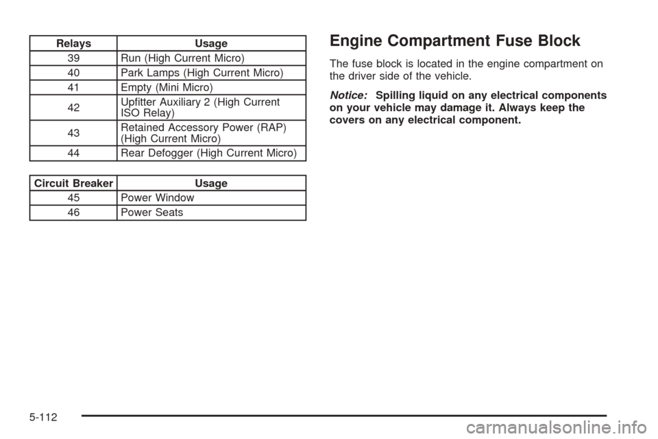
Relays Usage
39 Run (High Current Micro)
40 Park Lamps (High Current Micro)
41 Empty (Mini Micro)
42Upfitter Auxiliary 2 (High Current
ISO Relay)
43Retained Accessory Power (RAP)
(High Current Micro)
44 Rear Defogger (High Current Micro)
Circuit Breaker Usage
45 Power Window
46 Power Seats
Engine Compartment Fuse Block
The fuse block is located in the engine compartment on
the driver side of the vehicle.
Notice:Spilling liquid on any electrical components
on your vehicle may damage it. Always keep the
covers on any electrical component.
5-112
Page 409 of 414

Light (cont.)
StabiliTrak®Indicator....................................3-36
Tire Pressure..............................................3-37
Tow/Haul Mode...........................................3-43
Lighting
Entry/Exit...................................................3-17
Lights
Exterior Lamps............................................3-14
Flash-to-Pass............................................... 3-9
High/Low Beam Changer................................ 3-9
On Reminder..............................................3-15
Loading Your Vehicle.......................................4-20
Locking Rear Axle............................................ 4-5
Lockout Protection............................................ 2-9
Locks
Automatic Door Lock..................................... 2-8
Automatic Door Unlock.................................. 2-8
Cargo Door Relocking.................................... 2-7
Delayed Locking........................................... 2-7
Door........................................................... 2-6
Lockout Protection......................................... 2-9
Power Door.................................................. 2-7
Programmable Automatic Door Locks............... 2-7
Rear Door Security Locks............................... 2-8
Loss of Control...............................................4-11M
Maintenance Schedule
Additional Required Services........................... 6-6
At Each Fuel Fill.........................................6-10
At Least Once a Month................................6-10
At Least Once a Year..................................6-11
At the First 100, 1,000 and 6,000 Miles
(160, 1 600 and 10 000km).......................6-10
Introduction.................................................. 6-2
Maintenance Footnotes.................................. 6-8
Maintenance Record....................................6-17
Maintenance Replacement Parts....................6-15
Maintenance Requirements............................. 6-2
Owner Checks and Services........................... 6-9
Recommended Fluids and Lubricants.............6-13
Scheduled Maintenance................................. 6-4
Using.......................................................... 6-3
Your Vehicle and the Environment................... 6-2
Malfunction Indicator Light................................3-38
Manual Seats................................................... 1-2
Manual, Using.................................................... iii
Manual Windows............................................2-14
Message
DIC Warnings and Messages........................3-52
Mirrors
Manual Rearview Mirror................................2-33
Outside Camper-Type Mirrors........................2-33
Outside Convex Mirror.................................2-34
7