2008 BMW 650I CONVERTIBLE rear entertainment
[x] Cancel search: rear entertainmentPage 59 of 264

Controls
57Reference
At a glance
Driving tips
Communications
Navigation
Entertainment
Mobility
Follow the system manufacturer's
instructions on installation and use of
LATCH child restraint systems in order not to
impair their protective function.<
Anchor points for LATCH mounts
Before attaching the LATCH child's seat, pull
the belt away from the region of the child
restraint fixing system.
Make sure that both of the lower LATCH
mounts have properly clicked into place
and that the child restraint system is resting
snugly against the backrest. Otherwise, the
protective action may be impeded.<
Rear seats
The mounting points for the LATCH anchors
are located at the positions indicated by arrows
in the gap between the seat and the backrest.
Coupe: child restraint system with
tether strap
Only use the top tether-strap mounting
points to secure child restraint systems,
otherwise the mounting points could be dam-
aged.
to arrows.
Placement of tether strap
Make sure that the tether strap is not
routed over sharp edges and does not
twist on its way to the upper mounting point;
otherwise, the belt may not properly secure the
child restraint system in the event of an acci-
dent.<
1Direction of travel
2Head restraints
3Tether strap hook
4Mounting point
5Rear window shelf/luggage compartment
floor
6Backrest
7Tether strap of child restraint system
Before using the mounting points, fold the head
restraint
* into its raised position.
1.Slide the head restraint into the bottom
position.
2.Guide the tether strap over the head
restraint.
3.Attach the tether strap hook to the mount-
ing point.
Page 63 of 264

Controls
61Reference
At a glance
Driving tips
Communications
Navigation
Entertainment
Mobility
The transmission mode and the currently
selected gear are displayed.
Engaging transmission position
>Do not leave the transmission position P
until the engine is running: interlock.
>With the vehicle stationary, depress the
brake pedal before shifting out of P or N;
otherwise the shift command will not be
executed: shiftlock.
To prevent the vehicle from creeping
after you select a driving position,
maintain pressure on the brake pedal until
you are ready to start.<
Engaging N, D, R
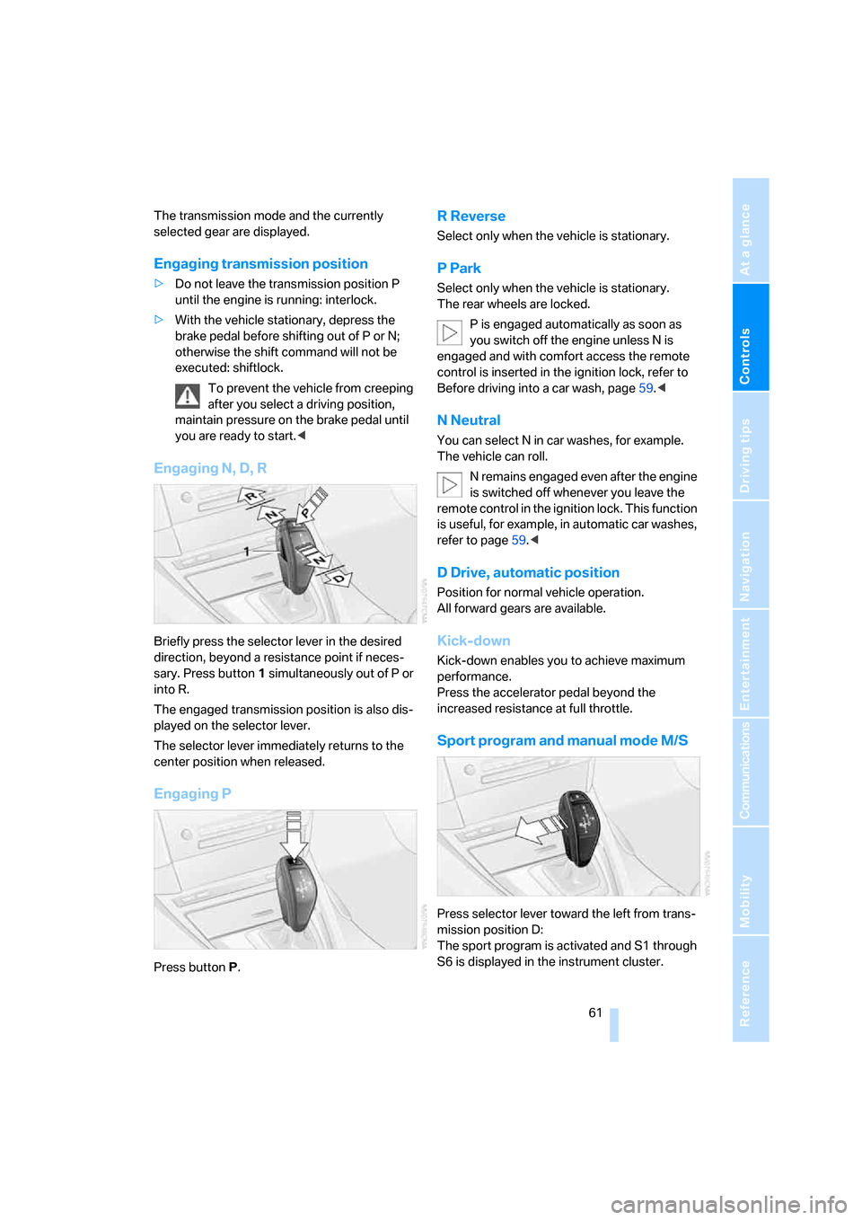
Briefly press the selector lever in the desired
direction, beyond a resistance point if neces-
sary. Press button1 simultaneously out of P or
into R.
The engaged transmission position is also dis-
played on the selector lever.
The selector lever immediately returns to the
center position when released.
Engaging P
Press buttonP.
R Reverse
Select only when the vehicle is stationary.
P Park
Select only when the vehicle is stationary.
The rear wheels are locked.
P is engaged automatically as soon as
you switch off the engine unless N is
engaged and with comfort access the remote
control is inserted in the ignition lock, refer to
Before driving into a car wash, page59.<
N Neutral
You can select N in car washes, for example.
The vehicle can roll.
N remains engaged even after the engine
is switched off whenever you leave the
remote control in the ignition lock. This function
is useful, for example, in automatic car washes,
refer to page59.<
D Drive, automatic position
Position for normal vehicle operation.
All forward gears are available.
Kick-down
Kick-down enables you to achieve maximum
performance.
Press the accelerator pedal beyond the
increased resistance at full throttle.
Sport program and manual mode M/S
Press selector lever toward the left from trans-
mission position D:
The sport program is activated and S1 through
S6 is displayed in the instrument cluster.
Page 65 of 264

Controls
63Reference
At a glance
Driving tips
Communications
Navigation
Entertainment
Mobility
the transmission lock after parking the vehicle
at its destination.
Releasing
1.Unclip the sleeve of the selector lever.
2.Pull the sleeve up over the selector lever.
3.Reach into the trim-piece opening, arrow1,
and firmly pull the trim piece upward,
arrow2.
4.Remove cover over the opening, refer to 5.
5.Insert a screwdriver from the onboard tool
kit, refer to page223, into the opening,
arrow1.
6.Pull the screwdriver toward the rear until it is
heard to engage, arrow2, and leave it
inserted in the opening. The transmission
lock is released.
Locking
1.Pull out the screwdriver upward.
The transmission lock is locked again.
2.Reinstall the cover and the trim piece.
Information on jump starting and towing from
page228.
Turn signals/
headlamp flasher
1High beams
2Headlamp flasher
3Turn signals
Using turn signals
Move the lever beyond the resistance point.
To switch off manually, only press the lever to
the resistance point.
Atypically rapid flashing of the indicator
lamp indicates the failure of a turn signal
lamp.<
Signaling briefly
Press the lever to the resistance point and hold
it there as long as you wish to signal.
Page 87 of 264

Controls
85Reference
At a glance
Driving tips
Communications
Navigation
Entertainment
Mobility
Technology for comfort, convenience and
safety
PDC Park Distance Control*
The concept
The PDC assists you when you are parking.
Acoustic signals and an optical display
* alert
you to the approach of an object from behind
your vehicle. To measure the distance, there
are four ultrasonic sensors in each bumper.
The range of these sensors is approx. 7 ft/2 m.
However, an acoustic warning first sounds for
the sensors at the front and at the two rear cor-
ners at approx. 24 in/60 cm, and for the center
rear sensors at approx. 5 ft/1.50 m.
PDC is a parking aid that can indicate the
presence of objects when they are being
approached slowly, as is usually the case when
parking. Avoid approaching an object at high
speed; otherwise, the physical circumstances
could cause the system warning to be activated
too late.<
Switching on automatically
The system starts to operate approx. one sec-
ond after you shift into reverse or move the
selector lever into position R with the engine
running or the ignition switched on.
Wait this short time before driving off.
Switching on manually
Press the button; the LED lights up.
Switching off manually
Press the button again; the LED goes out.
Automatic deactivation
After driving approx. 165 ft/50 m or at over
approx. 20 mph/30 km/h, the system is
switched off and the LED goes out. You can
reactivate the system manually as needed.
Signal tones
An intermittent signal indicates the distance of
the vehicle from an object being approached.
Thus, an object detected to the left rear of the
vehicle will be indicated by a signal tone from
the left rear speaker, etc. As the distance
between vehicle and object decreases, the
intervals between the tones become shorter. If
the distance to the nearest object falls to below
roughly 1 ft/30 cm, then a continuous tone
sounds.
An intermittent tone is interrupted after approx.
3seconds:
>if you remain in front of an object that was
only detected by one of the corner sensors
>if you drive parallel to a wall
Malfunction
The LED in the button flashes and a message
appears on the Control Display. PDC is mal-
functioning. Have the system checked.
As a preventive measure, keep the sensors
clean and free of ice or snow in order to ensure
that they will continue to operate effectively. Do
not spray the sensors with high-pressure clean-
ers for long periods and maintain a distance of
at least 4 in/10 cm to them.
Page 89 of 264

Controls
87Reference
At a glance
Driving tips
Communications
Navigation
Entertainment
Mobility
Electronic brake-force distribution
This system controls the brake system's appli-
cation pressure at the rear wheels to ensure
stable deceleration.
Brake assistant
When you apply the brakes rapidly, this system
automatically produces the maximum braking
force boost and thus helps to achieve the short-
est possible braking distance during full brak-
ing. This system exploits all of the benefits pro-
vided by ABS.
Do not reduce the pressure on the brake pedal
for the duration of the full braking.
Adaptive brake assistant*
In conjunction with the active cruise control
with the stop-and-go function, the adaptive
brake assistant ensures that the brake
responds even more quickly during braking
with the brake assistant.
DSC Dynamic Stability Control
DSC prevents traction loss in the driving wheels
when starting off and accelerating. The system
also identifies unstable driving conditions, such
as a loss of traction at the rear of the vehicle or
sliding of the vehicle in its front wheels. In these
cases, DSC helps the vehicle safely stay on
course within the physical limits by reducing the
engine output and by applying the brakes differ-
ently in the individual wheels.
The laws of physics cannot be repealed,
even with DSC. An appropriate driving
style always remains the responsibility of the
driver. Therefore, do not restrict the additional
safety margin with a risky driving style, as other-
wise there is a risk of an accident.<
Deactivating DSC
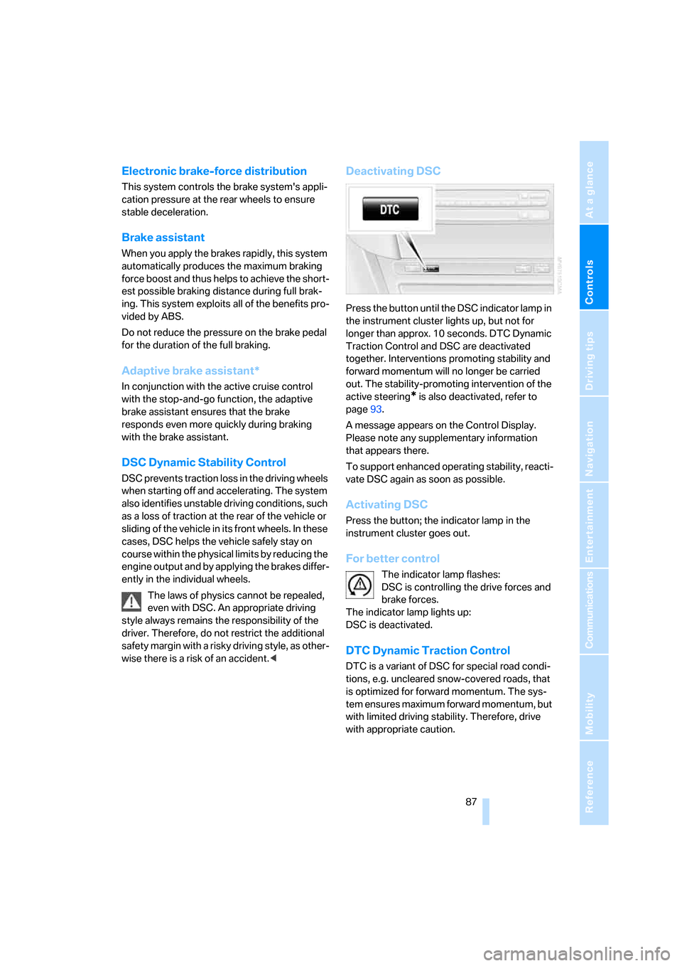
Press the button until the DSC indicator lamp in
the instrument cluster lights up, but not for
longer than approx. 10 seconds. DTC Dynamic
Traction Control and DSC are deactivated
together. Interventions promoting stability and
forward momentum will no longer be carried
out. The stability-promoting intervention of the
active steering
* is also deactivated, refer to
page93.
A message appears on the Control Display.
Please note any supplementary information
that appears there.
To support enhanced operating stability, reacti-
vate DSC again as soon as possible.
Activating DSC
Press the button; the indicator lamp in the
instrument cluster goes out.
For better control
The indicator lamp flashes:
DSC is controlling the drive forces and
brake forces.
The indicator lamp lights up:
DSC is deactivated.
DTC Dynamic Traction Control
DTC is a variant of DSC for special road condi-
tions, e.g. uncleared snow-covered roads, that
is optimized for forward momentum. The sys-
tem ensures maximum forward momentum, but
with limited driving stability. Therefore, drive
with appropriate caution.
Page 91 of 264

Controls
89Reference
At a glance
Driving tips
Communications
Navigation
Entertainment
Mobility
Dynamic Drive*
The concept
Dynamic Drive minimizes body roll and opti-
mizes vehicle stability during cornering and
evasive maneuvers.
Dynamic Drive is based on active stabilizers on
the front and rear axles. Suspension compli-
ance adapts to suit driving conditions, varying
from performance-oriented during cornering to
smooth and comfort-oriented when the vehicle
is proceeding in a straight line. During vehicle
operation, the system continuously runs
through closed-loop control cycles lasting only
fractions of a second.
The system assumes operational status each
time you start the engine.
FTM Flat Tire Monitor*
The concept
The Flat Tire Monitor detects a pressure loss in
one tire by comparing the speeds of the individ-
ual wheels during driving.
In the event of a pressure loss, there is a change
in the rolling circumference and therefore the
rotation speed of the corresponding wheel. The
system detects this change and reports it as a
flat tire.
Functional requirement
To ensure the reliable signaling of a flat tire, the
system must be initialized at the correct tire
inflation pressure.
The initialization must be repeated after
every correction of the tire inflation pres-
sure and after every tire or wheel change.<
System limits
The Flat Tire Monitor cannot indicate sudden
severe tire damage caused by outside factors
and does not detect a natural, even pressure
drop in all four tires.In the following situations, the system could be
delayed or malfunction:
>System has not been initialized
>Driving on snow-covered or slippery roads
>Sporty driving style: slip in the drive wheels,
high lateral acceleration
>Driving with snow chains
*
Initializing system
The initialization finishes during driving,
which can be interrupted at any time.
When driving resumes, the initialization is auto-
matically continued.
Do not initialize the system when driving with
snow chains
*.<
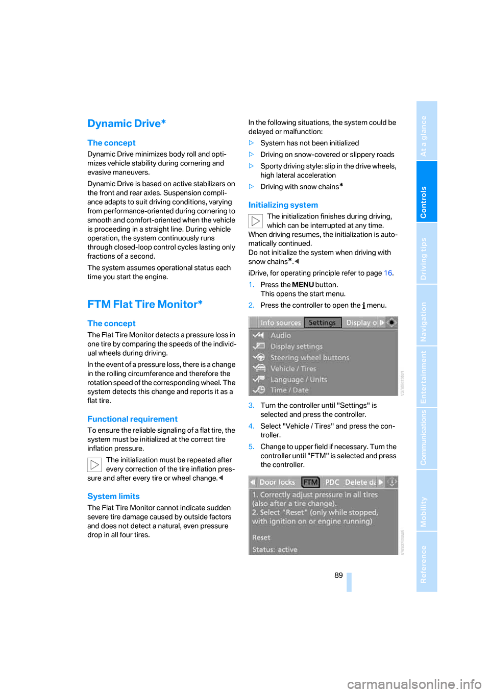
iDrive, for operating principle refer to page16.
1.Press the button.
This opens the start menu.
2.Press the controller to open the menu.
3.Turn the controller until "Settings" is
selected and press the controller.
4.Select "Vehicle / Tires" and press the con-
troller.
5.Change to upper field if necessary. Turn the
controller until "FTM" is selected and press
the controller.
Page 97 of 264

Controls
95Reference
At a glance
Driving tips
Communications
Navigation
Entertainment
Mobility
The front, knee and side airbags on the front
passenger side can be deactivated for teenag-
ers and adults in certain sitting positions; the
indicator lamp for the front passenger airbags
lights up when this occurs. In these cases,
change the sitting position so that the front pas-
senger airbags are activated and the indicator
lamp goes out. If the desired status cannot be
produced by changing the sitting position,
transport the corresponding person in the rear
seat.
Do not fit seat covers, seat cushion padding,
beaded mats or other items onto the front pas-
senger seat unless they are specifically recom-
mended by BMW. Do not place objects under
the seat which could press against the seat
from below. Otherwise, a correct evaluation of
the occupied seat surface cannot be ensured.<
Operating state of front passenger
airbags
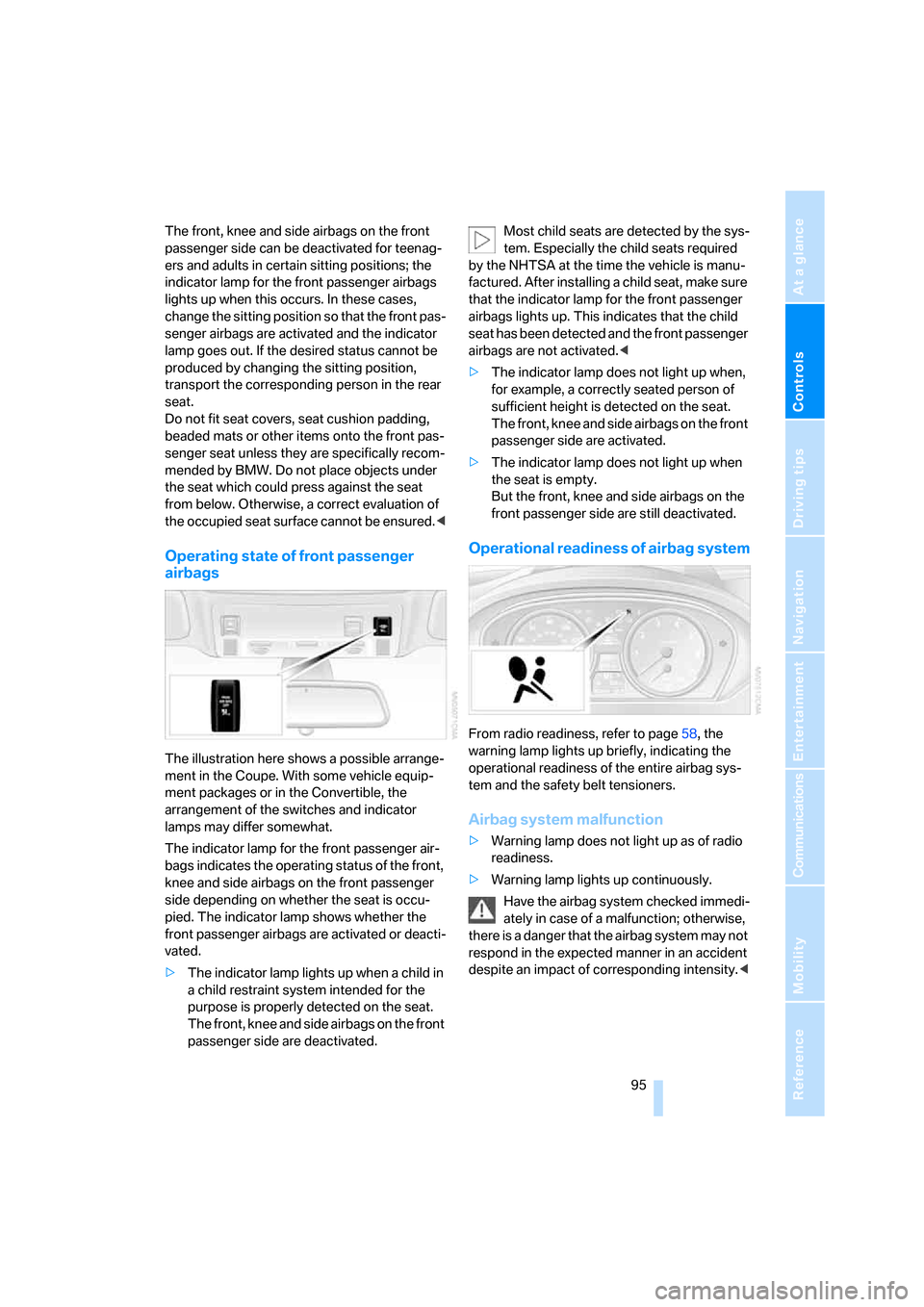
The illustration here shows a possible arrange-
ment in the Coupe. With some vehicle equip-
ment packages or in the Convertible, the
arrangement of the switches and indicator
lamps may differ somewhat.
The indicator lamp for the front passenger air-
bags indicates the operating status of the front,
knee and side airbags on the front passenger
side depending on whether the seat is occu-
pied. The indicator lamp shows whether the
front passenger airbags are activated or deacti-
vated.
>The indicator lamp lights up when a child in
a child restraint system intended for the
purpose is properly detected on the seat.
The front, knee and side airbags on the front
passenger side are deactivated.Most child seats are detected by the sys-
tem. Especially the child seats required
by the NHTSA at the time the vehicle is manu-
factured. After installing a child seat, make sure
that the indicator lamp for the front passenger
airbags lights up. This indicates that the child
seat has been detected and the front passenger
airbags are not activated.<
>The indicator lamp does not light up when,
for example, a correctly seated person of
sufficient height is detected on the seat.
The front, knee and side airbags on the front
passenger side are activated.
>The indicator lamp does not light up when
the seat is empty.
But the front, knee and side airbags on the
front passenger side are still deactivated.
Operational readiness of airbag system
From radio readiness, refer to page58, the
warning lamp lights up briefly, indicating the
operational readiness of the entire airbag sys-
tem and the safety belt tensioners.
Airbag system malfunction
>Warning lamp does not light up as of radio
readiness.
>Warning lamp lights up continuously.
Have the airbag system checked immedi-
ately in case of a malfunction; otherwise,
there is a danger that the airbag system may not
respond in the expected manner in an accident
despite an impact of corresponding intensity.<
Page 101 of 264

Controls
99Reference
At a glance
Driving tips
Communications
Navigation
Entertainment
Mobility
Any improvement in detection depends on
many factors such as the object size and tem-
perature compared to the surroundings, or
other nearby objects, the visual recognition
skills of the driver, weather conditions, and
other factors.
Driving hints
With the system active, periodically but briefly,
glance at the thermal image on the Control Dis-
play to notice objects that could be people or
larger animals. The glance should be similar to
glancing at the rear view mirror. Do not stare at
the image for long periods while driving, as this
will remove attention from the road. If you notice
an object of interest ahead, be prepared to slow
down or stop, blow the horn, or take other
appropriate action.
System limits
The system is designed to supplement but not
replace forward vision through the windshield.
The driver is responsible for safe driving at
night. BMW Night Vision is not designed to be
used as a continuous viewing window for driv-
ing at night.
No system, no matter how sophisticated, can
operate without limitations. BMW Night Vision
operation is subject to physical and environ-
mental limitations that will reduce the ability of
the system to detect and display a clear thermal
image. Some of the situations in which these
limitations can occur are:
>on steep hilltops or depressions and in tight
curves
>in tunnels, as the contrast is inherently low
>when the camera lens is dirty>in dense fog, heavy rain or snowfall
>when displaying very hot objects such as
transformers, car exhausts etc.
>when the image briefly freezes during nor-
mal system adjustment.
BMW Night Vision's potential benefits
can be limited by the driving style of the
driver, the size and relative temperature of the
detected objects, dirt or contamination on the
camera lens, adverse weather like snow, rain or
fog, and other factors not mentioned here. It will
always be the driver's responsibility to drive at a
speed and in a manner that recognizes potential
hazards and adjust accordingly.
BMW Night Vision is not a substitute or replace-
ment for driver responsibility or for accommo-
dating the visibility conditions and the traffic sit-
uation. The forward view illuminated by the
headlamps must always be the basis for making
safe driving decisions, otherwise a safety risk
will result.<
Activating BMW Night Vision
1.Turn the light switch to position2 or3, refer
to page102.
2.With low beams switched on:
>Press the button. Depending on the
vehicle's equipment, the location of the
button may differ somewhat.
>Press one of the programmable buttons
on the steering wheel, refer to page55.
The image will be displayed on the Control Dis-
play after a few seconds. Depending on the last
mode selected, either the normal or full screen
image will be displayed.